Riele Photometer 5010 V5+ User manual

Photometer 5010 V5+
Version 5.x
> SN 7000
Service Manual

3.1 BLOCK DIAGRAM (up to SN 8001)
RIELE BERLIN Photometer 5010 V5+ 3.1.1 29.08.2007

3.1 BLOCK DIAGRAM (from SN 8002)
RIELE BERLIN Photometer 5010 V5+ 3.1.2 29.08.2007

3.2 SHORT INSTRUCTION GUIDE
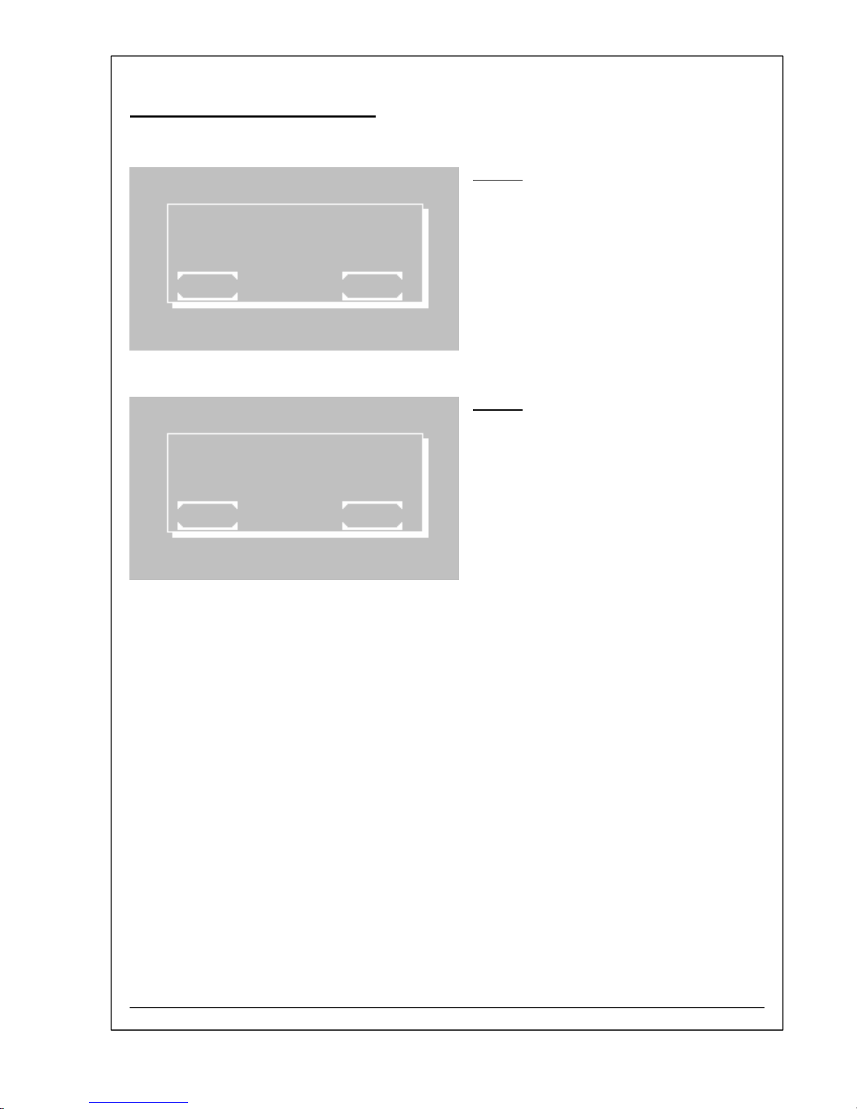
Utility programs
Main menu:
Utility programs are necessary for the adjustment
and maintenance of the photometer.
Page 1 of utility programs:
Scrolling through all utility programs is possible
by [PAGE]. The current page is shown at the right
upper screen corner. By [EXIT] the program
returns to the main menu.
A utility program is selected by pressing the
relating key.
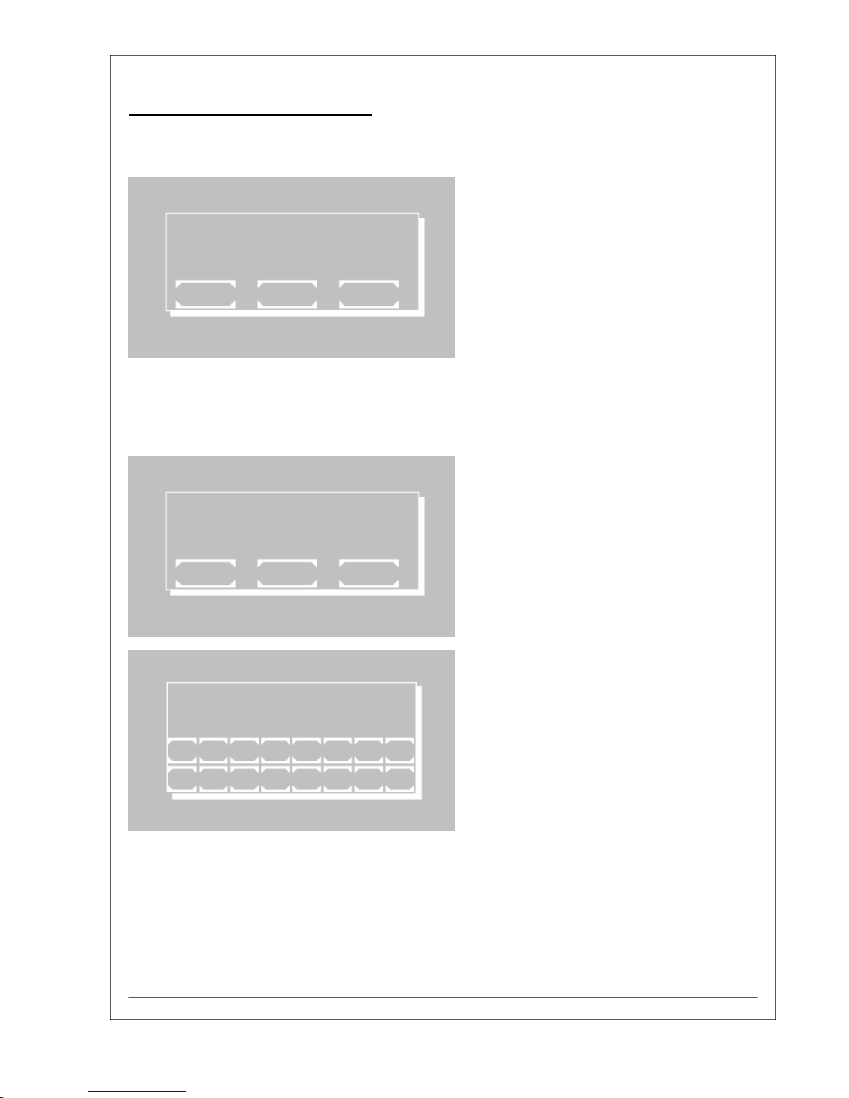
Page 5 of utility programs:
The last key is representing the service tools.
MAIN MENU
MEASURE WITH PROGR. METHODS
MEASURE WITH BASIC METHODS
MEASURE NEW / CHANGE / COPY
UTILITIES LAMP LF
37.03C 22.11.07 11:39
UTILITIES PAGE 1/5
DARK ADJUSTMENT PAGE
MULTI-STANDARD
PRINTER
PUMP / BUBBLE DETECT EXIT
37.01C 22.11.07 13:05
UTILITIES PAGE 5/5
LANGUAGE PAGE
ADC COUNTS (OPTIC)
SERVICE TOOLS EXIT
37.01C 22.11.07 13:05
RIELE BERLIN Photometer 5010 V5+ 3.2.1 12.03.2009

3.2 SHORT INSTRUCTION GUIDE
The service tools are reserved for trained
specialists only and therefore protected by a
password.
The password is given as
[ 1 3 4 6 7 ]
Stop function by [ESC].
SERVICE TOOLS
PASSWORD
1 2 3 4 5 6 7 8
ESC 9 0 . + - E
Utilities
Description in
chapter
of OM
Dark adjustment 7.2.1
Multi-standard function 7.2.2
Printer ON / OFF 7.2.3
Pump / bubble detector 7.2.4
Menu serial COM 7.2.5
Quality control 7.2.6
Settings printout 7.2.7
Data logging 7.2.8
Temperature ON / OFF 7.2.9
Temperature adjustment 7.2.10
Laboratory name 7.2.11
User name 7.2.12
Error list 7.2.13
Key signal ON / OFF 7.2.14
Touch panel adjustment 7.2.15
Date / Time 7.2.16
Language 7.2.17
ADC counts (Optic) 7.2.18
Send results 7.2.19
Service tools 7.2.20
RIELE BERLIN Photometer 5010 V5+ 3.2.2 12.03.2009

3.3 SERVICE TOOLS
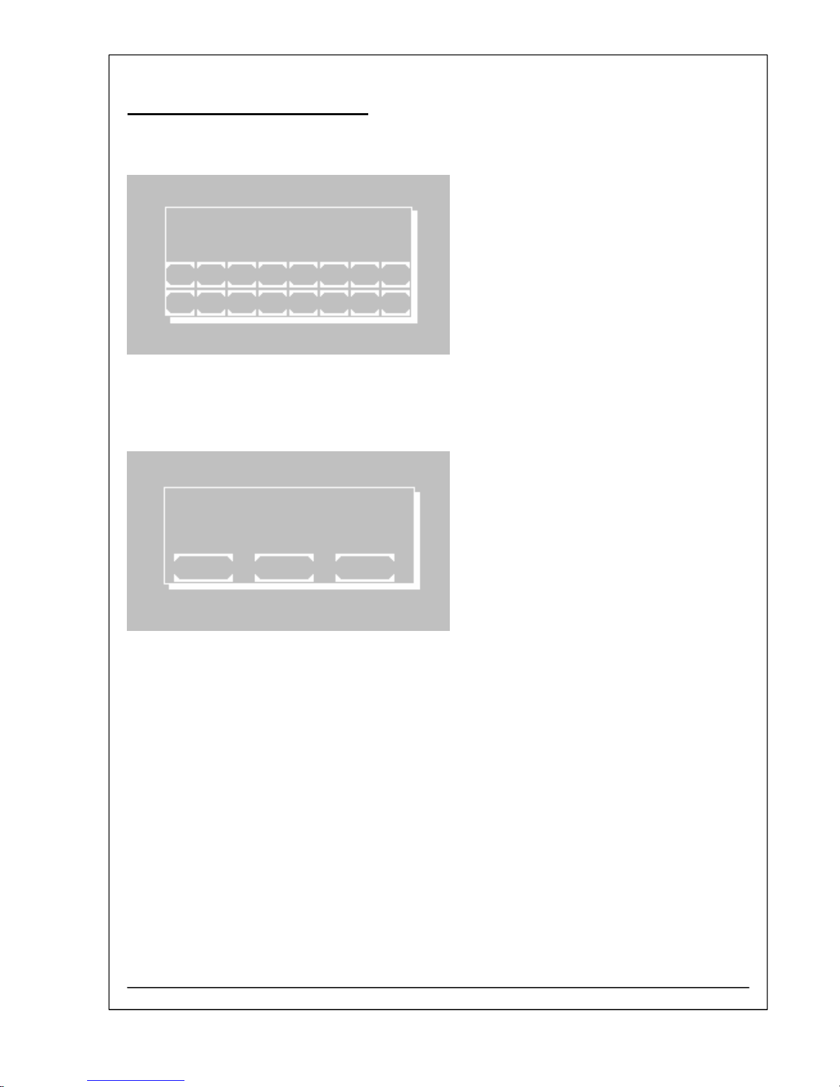
SELECTION OF SERVICE TOOLS
Within the service program level there are functions
influencing special basic parameters of the device.
Because they are allowed to be changed divergent
from the work configuration only in exceptions and only
by trained staff, their unintentional selection is
protected by a password.
Change in service program with
[SERVICE TOOLS].
Enter password:
[ 1 3 4 6 7 ]
Confirm with [E].
The service level will be opened until to the next
shutdown of the device.
UTILITIES PAGE 5/5
LANGUAGE PAGE
ADC COUNTS (OPTIC)
SERVICE TOOLS EXIT
SERVICE TOOLS
PASSWORD
1 2 3 4 5 6 7 8
ESC 9 0 . + - E
RIELE BERLIN Photometer 5010 V5+ 3.3.1 11.03.2009

3.3 SERVICE TOOLS
Selection of a desired service tool is possible with
[PAGE].
The current page is shown on the right upper corner of
the display.
Abort of service tool selection and change back to
program selection with [EXIT].
A service tool will be invoked by pushing the
corresponding button.
SERVICE TOOLS PAGE 1/6
SYSTEM INITIALISATION PAGE
MEMORY
DISPLAY TEST
LAMP EXIT
Item no. Service tool Description
in chapter
1 SYSTEM INITIALISATION S1
2 MEMORY S2
3 DISPLAY TEST S3
4 LAMP S4
5 SERIAL NO. S5
6 PCB LAYOUT S6
7 SET WAVELENGTH S7
8 TEST FILTER WHEEL S8
9 TEMPERATURE ON/OFF S9
10 TEMPERATURE VALUE S10
11 CORRECTION VALUE S11
12 TEMPERATURE CALIBRATION S12
13 ADC CORRECTION S13
14 ADC COUNTS (OPTIC) S14
15 ADC COUNTS (DARK ADJ.) S15
16 BOOST WAVELENGTH S16
17 CALIBRATION 12V ADC S17
18 DISTRIBUTOR TEXT INIT S18
19 AUTOMATIC RESULTS S19
20 BCC OF METHOD / CURVE S20
21 CLEAR FACTORS + RB S21
22 CLEAR ERROR LIST S22
23 PRINTER TEST S23
24 STACK TEST S24
RIELE BERLIN Photometer 5010 V5+ 3.3.2 11.03.2009

3.3 SERVICE TOOLS
DESCRIPTION OF SERVICE TOOLS
S1 System Initialisation
With [START] the default parameters will be set.
Several settings (see table) are then typed over in the
battery powered RAM. They remain active, even after
switching the device off/on, until they are specifically
changed.
[EXIT] leaves the function without any changes.
After a print-out of the program release the date and
time can be set (chapter OM 7.2.16).
The action ends with a long beep.
SYSTEM INITIALISATION
EXIT START
DATE TIME
mm.dd.yy hh:mm:ss
10.12.05 14:54:34
1 2 3 4 5 6 7 8
ESC 9 0 . + - E
Beeper ON
Printer internal ON
Printer external OFF
Real time clock ON
Boost mode up to 390 nm
Language English
Analog-digital converter correction 150
Temperature control: Correction values 3000
EDP OFF
EDP protocol STX / ETX / BCC
Resulting factors of methods based on standard not affected
Error list not affected
Laboratory name not affected
User name not affected
Data logging not affected
Quality control not affected
Multi-standard functions not affected
Bubble detector ON
RIELE BERLIN Photometer 5010 V5+ 3.3.3 11.03.2009

3.3 SERVICE TOOLS
S2 Memory
The submenu shows different kinds of memory.
SERVICE TOOLS SUB MENU
DELETE FREE METHODS
MULTI-STD MEMORY
DEL. LOGGER MEMORY
DEL. QC MEMORY EXIT
S2.1 Delete Free Methods
Attention! With [START] all methods edited by the user
are deleted without a call-back. In the case of doubt
these methods should be checked before: A print out of
all stored methods can be done for an optional later
new programming.
The action ends with a long beep.
[EXIT] leaves the function without any changes.
DELETE FREE METHODS
EXIT START
S2.2 Multi-Standard Memory
Attention! With [DEL] the memory assigned to nonlinear
methods is deleted without a call-back.
The contents of the memory can be exported and
imported by special remote commands (chapter 6.1 –
Communication protocol).
The action ends with a long beep.
[EXIT] leaves the function without any changes.
MULTI-STD MEMORY
EXIT DEL SET
RIELE BERLIN Photometer 5010 V5+ 3.3.4 11.03.2009
3.3 SERVICE TOOLS
S2.3 Delete Logger Memory
Attention! With [START] the memory assigned to stored
results is deleted without a call-back.
The action ends with a long beep.
[EXIT] leaves the function without any changes.
DEL. LOGGER MEMORY
EXIT START
S2.4 Delete QC Memory
Attention! With [START] the memory assigned to QC
data is deleted without a call-back.
The action ends with a long beep.
[EXIT] leaves the function without any changes.
DEL. QC MEMORY
EXIT START
RIELE BERLIN Photometer 5010 V5+ 3.3.5 11.03.2009

3.3 SERVICE TOOLS
S3 Display Test
The display test is invoked with [START].
For three seconds all pixels of the touch screen are
illuminated.
The test terminates by itself.
[EXIT] leaves the function without any changes.
DISPLAY TEST
EXIT START
S4 Lamp
The function shows the current lamp voltage. The value
is shown in the second line (e.g. 12.13 V).
With [MIN.] the lamp voltage can be temporarily
reduced. In case of the adjustment of the optical path
the light spot is better to be seen.
With [MAX.] the lamp voltage arises to its normal value.
[EXIT] leaves the function without any changes.
LAMP
12.13V
EXIT MIN.
S5 Serial No.
The current serial number of the device can be read
and set. The number (e.g. 7001) is shown on the right
upper corner of the window.
A new number can be entered with maximum five
digits.
The input has to be confirmed with [E].
SERIAL NO. 7001
1 2 3 4 5 6 7 8
ESC 9 0 . + - E
RIELE BERLIN Photometer 5010 V5+ 3.3.6 11.03.2009
3.3 SERVICE TOOLS
S6 PCB Layout
The attribute of the PCB layout can be read and set.
The attribute (e.g. c) is shown on the right upper corner
of the window.
Software applications may be depend on this attribute.
The attribute is labelled on the PCB RR_120 near plug
ST13.
The attribute can be changed with [SELECT].
The input has to be confirmed with [OK].
[EXIT] leaves the function without any changes.
PCB LAYOUT c
EXIT OK SELECT
S7 Set Wavelength
The assignment of wavelength and filter position can
be done.
The current filter position is blinking.
With [SELECT] the filter position can be set.
With [NEW] the wavelength can be edited.
[EXIT] leaves the function without any changes.
In the first line the current filter position is shown.
The new value of the wavelength has to be entered.
The input has to be confirmed with [E].
SET WAVELENGTH
1: 340 6: 623
2: 405 7: 999
3: 492 8: 999
4: 546 9: 999
5: 578
EXIT NEW SELECT
NEW WAVELENGTH 1
1 2 3 4 5 6 7 8
ESC 9 0 . + - E
RIELE BERLIN Photometer 5010 V5+ 3.3.7 11.03.2009
3.3 SERVICE TOOLS
S8 Test Filter Wheel
The rotation of the filter wheel can be controlled.
With [F0] up to [F9] the discrete positions of the filter
wheel can be selected.
A specific value (e.g. 399MS) shows the rotation of the
filter wheel. The abbreviation MS is used for motor
step.
TEST FILTER WHEEL
F1 340nm 399MS
F1 F2 F3 F4 F5 F6 F7 F8
ESCF9 F0
S9 Temperature ON/OFF
The temperature regulation can be switched on or
switched off. The current setting is shown in the first
line as ON or OFF.
The display shows additionally the following
information:
•a D in case of an inserted flow through cuvette
adaptor
•an E in case of an inserted standard cuvette
adaptor
•the required value of temperature regulation
•the actual value of temperature regulation
•the stability value
•the current value of ADC
With [SELECT] the temperature level can be chosen.
With [OK] the temperature regulation is started.
[EXIT] leaves the function without any changes.
TEMPERATURE 37C ON D
OFF REQUIRED 14165
25C ACTUAL 14053
30C STABILITY 4
37C CONVERTER 947
EXIT OK SELECT
RIELE BERLIN Photometer 5010 V5+ 3.3.8 11.03.2009

3.3 SERVICE TOOLS
S10 Temperature Value
The temperature values of the device can be read and
set. A new value can be entered with maximum five
digits.
With [SELECT] a specific temperature value can be
set. The temperature values are marked as E25, E30,
E37, D25, D30 and D37 corresponding to the type of
adaptor (E or D) and the temperature level (25° C,
30° C and 37° C).
The cursor of the current temperature value is blinking.
With [NEW] a temperature value can be edited.
Enter temperature value. Confirm with [E].
(chapter 4.40 - Thermal adjustment)
TEMPERATURE VALUE
E25 8322 D25 8299
E30 9552 D30 9485
E37 11273 D37 11165
EXIT NEW SELECT
NEW VALUE
1 2 3 4 5 6 7 8
ESC 9 0 . + - E
S11 Correction Value
The correction values of the device can be read and
set. A new value can be entered with maximum five
digits.
With [SELECT] a specific correction value can be set.
The correction values are marked as E25, E30, E37,
D25, D30 and D37 corresponding to the type of
adapter (E or D) and the temperature level (25° C,
30° C and 37° C).
The cursor of the current correction value is blinking.
With [NEW] a correction value can be edited.
Enter correction value. Confirm with [E].
CORRECTION VALUE
E25 3000 D25 3000
E30 3000 D30 3000
E37 3000 D37 3000
EXIT NEW SELECT
NEW VALUE
1 2 3 4 5 6 7 8
ESC 9 0 . + - E
RIELE BERLIN Photometer 5010 V5+ 3.3.9 11.03.2009

3.3 SERVICE TOOLS
S12 Temperature Calibration
The correction of the temperature regulation is possible
by input of the temperature value which is measured in
the cuvette with an external measuring system
(Thermistor and DMM).
This function is available only when the temperature
regulation is stabilized. In an unstable condition an
error message is shown on the display.
Enter the actual temperature value always four-digit in
° C e.g. [3] [7] [.] [2] [0] measured by an external
measuring system.
Confirm with [E].
The system calculates and stores the new setting for
the selected temperature level and starts working with it
at once.
TEMP. CALIBRATION
TEMP. ACTUAL :
1 2 3 4 5 6 7 8
ESC 9 0 . + - E
S13 ADC Correction
The current ADC correction of the device can be read
and set.
The range of this value is 0 up to 255. The default
value is 150.
The input has to be confirmed with [E].
ADC CORRECTION 150
1 2 3 4 5 6 7 8
ESC 9 0 . + - E
S14 ADC Counts (Optic)
Indicated is the current value of the optical analogue-
digital converter. The value is proportional to the light-
current depending on the selected amplification level
and the boost setting.
To a key actuation the system reacts possibly only after
three seconds.
The functions V0 to V7 set the amplification level. The
function BO increases (boost ON) or reduces (boost
OFF) the time slot. The functions F0 to F9 place the
filter wheel into the positions 0 to 9. The position 0
corresponds to the filter wheel position at the dark level
adjustment.
Stop function by [ESC].
ADC COUNTS (OPTIC)
BOOST OFF
V0 F1 340nm 18810
V0 V1 V2 V3 V4 V5 V6 V7 B0.
F0 F1 F2 F3 F4 F5 F6 F7 F8 F9
ESC
RIELE BERLIN Photometer 5010 V5+ 3.3.10 11.03.2009

3.3 SERVICE TOOLS
S15 ADC Counts (Dark Adjustment)
The ADC values of the dark adjustment can be read.
The display shows the following information:
•a D in case of a preselected flow through cuvette
adaptor
•an E in case of a preselected standard cuvette
adaptor
•the ADC values assigned to the amplification levels
V0 up to V7
With [E/D] the display shows alternately the values in
combination with the different adaptors E or D.
ADC COUNTS (DARK ADJ.)
E
0: 18425 1: 18428
2: 18433 3: 18442
4: 18457 5: 18483
6: 18534 7: 18630
EXIT E/D
S16 Boost Wavelength
To improve the low light gain at small wavelengths, the
measurement time is extended when operating below a
definite wavelength. This definite wavelength will be
displayed on the right upper corner of the window.
The default value is 390 nm.
The input has to be confirmed with [E].
BOOST WAVELENG 390nm
1 2 3 4 5 6 7 8
ESC 9 0 . + - E
RIELE BERLIN Photometer 5010 V5+ 3.3.11 11.03.2009

3.3 SERVICE TOOLS
S17 Calibration 12V ADC
In the first line the actual value of the voltage 12 V
DC
is
to be seen (e.g. 12.02V).
The internal measuring unit can be calibrated by
pushing [START].
It is assumed that the adjustment of the voltage 12 V
DC
of halogen lamp is done properly (chapter 4.40 –
Voltage 12 V
DC
of halogen lamp).
The procedure is finished by [EXIT].
CAL.12V ADC 12.02V
EXIT START
S18 Distributor Text Init
The distributor text shown after switching on the
Photometer 5010 V5+ will be erased by invoking
[START].
[EXIT] leaves the function without any changes.
A new distributor text can be set by software “Serial
Monitor 5010” (chapter 4.9).
DISTRIBUTOR TEXT INIT
EXIT START
RIELE BERLIN Photometer 5010 V5+ 3.3.12 11.03.2009

3.3 SERVICE TOOLS
S19 Automatic Results
This operation works only with standard cuvette
adapter!
The function invokes by [START] a test based on the
calculation procedure 1 ↔C/F (OM chapter 5.4.1).
For each setting parameter a leading identification
number is shown. If the identification number is
selected on the keyboard, the corresponding setting
parameter becomes configurable.
After setting parameters like wavelength, factor, delay
time, unit, … the procedure is started by [OK].
By setting delay time the intervals between the
measurements can be defined.
The procedure is working in an open loop and
produces results as long as the [EXIT] is pushed.
By [ZERO] an automatic zero adjustment can be done.
To a key actuation the system reacts possibly only after
three seconds.
AUTOMATIC RESULTS
EXIT START
METHOD NO. 1 C/F
1-WAVELENGTH 340nm
2-FACTOR 1.000 EXIT
3-TEMPERATURE 37C
4-DELAY 0s
5-UNIT OK
6-
7-
8-
1 2 3 4 5 6 7 8 P1/3
DELAY 5 C/F
42
EXIT MODE WASH ZERO RESULT
1.234
S20 BCC of Method/Curve
To check the correct storing of a user-defined method
or curve, the special test byte BCC concerning the data
in the memory is used. With this service program the
BCC of a method can be determined.
With [M] the BCC of a method can be tested.
With [C] the BCC of a curve can be tested.
BCC OF METHOD/CURVE
EXIT M C
RIELE BERLIN Photometer 5010 V5+ 3.3.13 11.03.2009

3.3 SERVICE TOOLS
S21 Clear factors + RB
The determined resulting factor of a standard
measurement and the reagent blank (RB) is stored
together with the corresponding method number. After
renewed selection of this method the last resulting
factor is offered as "OLD STD", the reagent blank (RB)
is offered as “OLD RB”.
All resulting factors and reagent blanks (RB) will be
erased by invoking [START].
[EXIT] leaves the function without any changes.
CLEAR FACTORS + RB
EXIT START
S22 Clear error list
The last 10 serious errors are shown or printed.
The complete error list will be erased by invoking
[START].
[EXIT] leaves the function without any changes.
CLEAR ERROR LIST
EXIT START
S23 Printer test
A special printout for testing the printer ribbon or the
hardware is produced.
The printout is started by invoking [START].
[EXIT] leaves the function without any changes.
PRINTER TEST
EXIT START
RIELE BERLIN Photometer 5010 V5+ 3.3.14 11.03.2009

3.3 SERVICE TOOLS
S24 Stack test
The address pointer of the stack can be controlled.
The attribute can be changed with [SELECT].
•ON = only for development purposes
•OFF = normal position
The setting has to be confirmed with [OK].
[EXIT] leaves the function without any changes.
STACK TEST OFF
EXIT OK SELECT
RIELE BERLIN Photometer 5010 V5+ 3.3.15 11.03.2009
Other manuals for Photometer 5010 V5+
1
Table of contents
Other Riele Measuring Instrument manuals


