Riello E 5202 Quick start guide

2916224 (8) - 09/2021
Istruzioni per installazione, uso e manutenzione
Installations-, Montage- und Betriebsanleitung
Installation, use and maintenance instructions
Instructions d’installation, montage et fonctionnement
Kit convertitore di segnale analogico
Analogischer Signalwandler-Kit
Analogic signal converter kit
Kit convertisseur de signal analogique
CODICE - CODE TIPO BRUCIATORE - BRENNER TYP
BURNER TYPE - BRÛLEURS TYPE
3010390 RS 28-38-50 VA - RS 38-50-64/M
RS 300-400-500/M - RS 300-400/P
3010410 RS 25-34-35-44/M
3010415 RS 70-100-130-150-160-190-200-250/M
20074479 RS 310-410-510-610/M
I
D
GB
F
E 5202


1 2916224
I
Avvertenze generali
1.1 Garanzia e responsabilità
I diritti alla garanzia ed alla responsabilità decadono, in caso di
danni a persone e/o cose, qualora i danni stessi siano riconduci-
bili ad una o più delle seguenti cause:
intervento di personale non abilitato;
esecuzione di modifiche non autorizzate all’apparecchio;
alimentazione del bruciatore con combustibili non adatti;
difetti nell’impianto di alimentazione del combustibile;
riparazioni e/o revisioni eseguite in maniera scorretta;
utilizzo di componenti non originali, siano essi ricambi, kits,
accessori ed optionals;
cause di forza maggiore.
Il costruttore, inoltre, declina ogni e qualsiasi responsabilità per la
mancata osservanza di quanto riportato nel presente manuale.
– Il personale deve usare sempre i mezzi di protezione indivi-
duale previsti dalla legislazione e seguire quanto riportato nel
presente manuale.
– Il personale deve attenersi a tutte le indicazioni di pericolo e
cautela segnalate sulla macchina.
– Il personale non deve eseguire di propria iniziativa operazioni
o interventi che non siano di sua competenza.
– Il personale ha l’obbligo di segnalare al proprio superiore
ogni problema o situazione pericolosa che si dovesse creare.
1.2 Note sulla sicurezza per l'installazione
1 Avvertenze generali
PERICOLO
Tutte le operazioni di installazione, manutenzione
e smontaggio devono essere svolte con l'alimen-
tazione elettrica staccata.
PERICOLO
Isolare l'alimentazione del combustibile.
ATTENZIONE
L'installazione deve essere svolta da personale
qualificato, come indicato in questo manuale e in
conformità con gli standard e le disposizioni di leg-
ge in vigore.
CAUTELA
Dopo aver tolto ogni imballaggio assicurarsi
dell’integrità del contenuto. Nel dubbio, non utiliz-
zare il kit ricambio; rivolgersi al fornitore.
Attendere il completo raffreddamento dei compo-
nenti a contatto con fonti di calore.
Effettuate tutte le operazioni di manutenzione, pu-
lizia o controllo, rimontare il cofano e tutti i dispo-
sitivi di sicurezza e protezione del bruciatore.

2916224 2
I
Kit convertitore di segnale
2.1 Descrizione kit
Il convertitore E 5202 è uno specifico dispositivo dedicato alla ge-
stione di servomotori (pilotati con comando a 3 punti) e al control-
lo della loro posizione quando il segnale in ingresso proveniente
da un dispositivo principale di controllo è un segnale standard
analogico 0/4÷20mA o 0/2÷10V.
Deve essere collegato ad un potenziometro da ordinare a parte
con un codice specifico, come indicato nella Tab. A.
Tab. A
2.2 Dati tecnici
Tab. B
2.3 Dimensioni di ingombro e foratura pannello
2 Kit convertitore di segnale
Codice Kit Convertitore di segnale Applicazione su bruciatori serie Kit potenziometro
3010390
RS 28-38-50 VA 3020072
RS 38-50-64/M 3010109
RS 300-400-500/M 3010402
RS 300-400/P 3010393
3010410 RS 25-34-35-44/M 3010420
3010415 RS 70-100-130-150-160-190-200-250/M 3010416
20074479 RS 310-410-510-610/M 20074487
Segnali in ingresso 0/2÷10V (impedenza 200 k)
0/4÷20mA (impedenza 250 )
selezionabili tramite ponticelli dal retro
Reazione Potenziometro a 3 fili 1÷20 k
Uscita Relè con contatto N.A., portata massima 250Vac 5A
Isteresi (banda morta) Aggiustabile con trimmer frontale ±0,1% a ±1%
Alimentazione elettrica 115Vac / 230Vac 50÷60Hz
Potenza elettrica assorbita 3VA max
Temperatura di funzionamento 50°C max
Temperatura di immagazzinamento -20 ... +70°C
Contenitore Resina ABS autoestinguente
Grado di protezione IP40
Approvazioni CE (EMC secondo EN 50081-1, EN 50082-2)
(Sicurezza elettrica secondo EN 61010-1)
Fig. 1

3 2916224
I
Kit convertitore di segnale
2.4 Collegamenti morsettiera
2.5 Segnale in ingresso
Il segnale di ingresso può essere facilmente adattato alla corsa
del servomotore, come riportato di seguito:
o per altre applicazioni:
2.6 Regolazione del convertitore E 5202
Il convertitore non richiede una taratura specifica; esso
adatta la posizione del servomotore al segnale di ingresso 0/
4÷20mA (o 0/2÷10V) tramite l’abbinamento al valore della
resistenza del potenziometro.
Il convertitore è equipaggiato da un trimmer (Banda Morta)
posizionato nel pannello frontale; si raccomanda comunque
di regolare il trimmer al valore massimo, (Trim completa-
mente ruotato in senso orario), per evitare una reazione
troppo frequente con inutile riposizionamento del servomo-
tore nel caso di variazione del segnale di ingresso molto pic-
cola.
Il valore massimo della Banda Morta è 1%, che corrisponde
a nessuna reazione di riposizionamento fino a che la varia-
zione del segnale in ingresso è maggiore di 0,2 mA (o 0,1V)
(angolo di circa 1°).
Fig. 2
123456789101112
230V
N
IN
+-
INC. DEC.
IN
V
mA
1 2 3 4 5 6 7 8 9 101112
115V
N
IN
+-
INC. DEC.
IN
V
mA
Impostazione di fabbrica
Alimentazione elettrica: 230V
Segnale in ingresso: 0/4÷20mA
Impostazioni opzionali (solo se necessario)
In caso di alimentazione elettrica 115V spostare il filo
dal morsetto 10 al morsetto 11.
In caso di segnale in ingresso 0/2÷10V spostare il pon-
ticello al morsetto V.
Fig. 3
2040
Stop
20%
100%
0%
[mA]
1020 [V]
POSIZIONE SERVOMOTORE
SEGNALE IN INGRESSO
Potenza minima
Potenza massima
4 ÷ 20mA corrispondono a
Posizione di MIN del servomotore ÷ Posizione di MAX del servomotore
(Potenza MIN ÷ Potenza MAX)
Vedere diagramma.
2 ÷ 10V corrispondono a
Posizione di MIN del servomotore ÷ Posizione di MAX del servomotore
(Potenza MIN ÷ Potenza MAX)
Vedere diagramma.
0 ÷ 20mA corrispondono a Posizione di chiusura del servomotore ÷ Posizione di MAX del servomotore
Vedere diagramma.
0 ÷ 10V corrispondono a Posizione di chiusura del servomotore ÷ Posizione di MAX del servomotore
Vedere diagramma.

2916224 4
I
Installazione
•
3.1 Installazione del potenziometro
Installare il Kit Potenziometro (da ordinare a parte) facendo
riferimento alle istruzioni fornite a corredo dello stesso.
Verificare il corretto montaggio controllando che la resi-
stenza di 1000 corrisponda esattamente alla corsa MAS-
SIMA del servomotore: angolo di 90° o 130° a seconda del
tipo di bruciatore.
Questa taratura non deve essere modificata.
Collegare il potenziometro a 3 fili direttamente al converti-
tore E 5202, come indicato negli schemi riportati di seguito.
Per il settaggio della posizione di MINIMA, fare riferimento
alla taratura di fabbrica del servomotore indicata nel
manuale a corredo del bruciatore.
3.2 Installazione Kit convertitore di segnale
I bruciatori sono già predisposti per l’installazione del convertitore
E 5202.
Inserire il convertitore nell’apposito supporto 1)(Fig. 4) o
1)(Fig. 5) e fissarlo con le due viti e staffe fornite a corredo del kit.
Collegare i cavi uscenti all’apposita morsettiera del bruciatore.
Vedere schema elettrico di Fig. 4 o Fig. 5.
3 Installazione
PERICOLO
Togliere l’alimentazione elettrica al bruciatore,
agendo sull’interruttore generale dell’impianto.
Codice 3010390
1
'
( (
)%
*
+
+
,
-
.
/
/
/
'
*
+
+
'.1
-9
#
.
'.
'.
1000/ 90° per bruciatori serie RS 38-50-64/M
20101658
20101659
Fig. 4
Segnale in
ingresso
4-20 mA / 0-10 V
D3935
Segnale in
ingresso
4-20 mA / 0-10 V
1000/ 135° per bruciatori serie RS 300-400-500/M
1000/ 90° per bruciatori serie RS 300-400/P
1
Fig. 5

5 2916224
I
Installazione
Inserire il convertitore nell’apposito supporto 1)(Fig. 6) e fissarlo
con le due viti e staffe fornite a corredo del kit.
Togliere il coperchio del pressostato 2)(Fig. 6) ed allentare le due
viti di fissaggio fino ad ottenere lo spazio necessario per infilare
la staffa 1)(Fig. 6), agganciandola alle viti stesse.
Durante questa operazione si rende necessario far passare il
cavo del pressostato all’interno della feritoia 3)(Fig. 6).
Scollegare la spina “A” presente sul collegamento bruciatore (da
conservare, necessaria per funzionamento senza kit).
Collegare la spina “B” del convertitore alla relativa presa sul bru-
ciatore.
Vedere schema elettrico di Fig. 6.
Inserire il convertitore nell’apposito supporto 1)(Fig. 7) e fissarlo
con le due viti e staffe fornite a corredo del kit.
Collegare la spina del convertitore alla relativa presa sul brucia-
tore.
Vedere schema elettrico di Fig. 7.
Codice 3010410
Fig. 6
20091804
Segnale in
ingresso
4-20 mA / 0-10 V
2
3
1
20091802
Codice 3010415
Fig. 7
D3936
1
Segnale in
ingresso
4-20 mA / 0-10 V

2916224 6
I
Installazione
– Tagliare lungo la linea evidenziata in 1)(Fig. 8);
– asportare la piastra di copertura 2)(Fig. 8), facendo leva con
un cacciavite nei quattro punti evidenziati;
– inserire il convertitore 3) nella staffa del bruciatore e fissare
con le 2 viti 4).
Collegamento elettrico:
– collegare la spina 5) uscente dal convertitore alla relati va
presa 6) del bruciatore.
Vedere schema elettrico di Fig. 9.
Codice 20074479
1
2
43
4
56
Fig. 8
20093518
20093571
20123712
90°
1000
Fig. 9
Segnale in
ingresso
4-20 mA / 0-10 V
20123509

1 2916224
D
Allgemeine Hinweise
1.1 Garantie und Haftung
Die Garantie- und Haftungsansprüche verfallen bei Personen-
und / oder Sachschäden, die auf einen oder mehrere der folgen-
den Gründe zurückzuführen sind:
Eingriffe durch nicht zugelassenes Personal;
Vornahme von nicht genehmigten Änderungen am Gerät;
Versorgung des Brenners mit ungeeigneten Brennstoffen;
Defekte in der Anlage zur Brennstoffzufuhr;
falsch ausgeführte Reparaturen und / oder Überprüfungen;
Verwendung von anderen als Original-Bauteilen als Ersatz-
teile, Bausätze, Zubehör und Optionals;
Ursachen höherer Gewalt.
Der Hersteller lehnt außerdem jegliche Haftung für die Nichtein-
haltung der Angaben in diesem Handbuch ab.
– Das Personal muss immer die durch die Gesetzgebung vor-
gesehenen persönlichen Schutzmittel verwenden und die
Angaben in diesem Handbuch beachten.
– Das Personal muss alle Gefahren- und Vorsichtshinweise
einhalten, die sich am Gerät befinden.
– Das Personal darf nicht aus eigenem Antrieb Arbeiten oder
Eingriffe ausführen, für die es nicht zuständig ist.
– Das Personal hat die Pflicht, dem jeweiligen Vorgesetzten
alle Probleme oder Gefahren zu melden, die auftreten soll-
ten.
1.2 Anmerkungen zur Sicherheit bei der Installation
1 Allgemeine Hinweise
GEFAHR
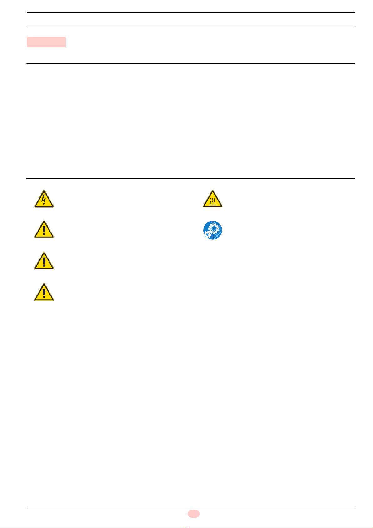
Sämtliche Installations-, Wartungs- und Ausbau-
arbeiten müssen bei gezogenem Netzstecker
durchgeführt werden.
GEFAHR
Die Brennstoffversorgung trennen.
ACHTUNG
Die Installation muss von Fachpersonal nach den
Angaben in diesem Handbuch und in Überein-
stimmung mit den geltenden Normen und gesetz-
lichen Bestimmungen durchgeführt werden.
VORSICHT
Prüfen Sie nach dem Entfernen der gesamten
Verpackung die Unversehrtheit des Inhalts. Im
Zweifelsfall das Ersatzteilkit nicht verwenden;
kontaktieren Sie den Lieferanten.
Warten Sie, bis die Bauteile, die mit Wärmequel-
len in Berührung kommen, komplett abgekühlt
sind.
Nach Durchführung von Wartungs-, Reinigungs-
oder Kontrollarbeiten müssen die Haube sowie
alle Sicherheits- und Schutzvorrichtungen des
Brenners wieder montiert werden.

2916224 2
D
Signalwandler-Kit
2.1 Beschreibung des Kits
Der Wandler E 5202 ist eine spezifische Vorrichtung, die zur
Steuerung von Servomotoren (pilotgesteuert mit 3-Punkt-Steue-
rung) und zur Kontrolle deren Position dient, wenn das Eingangs-
signal von einer Hauptsteuervorrichtung ein analoges
Standardsignal von 0/4÷20mA oder 0/2÷10V ist.
Er muss an ein Potentiometer angeschlossen sein, das separat
mit einem speziellen Code gemäß den Angaben in der Tab. A be-
stellt werden kann.
Tab. A
2.2 Technische Daten
Tab. B
2.3 Abmessungen und Plattenbohrung
2 Signalwandler-Kit
Code Signalwandler-Kit Anwendung bei Brennern der Serie Potentiometer-Kit
3010390
RS 28-38-50 VA 3020072
RS 38-50-64/M 3010109
RS 300-400-500/M 3010402
RS 300-400/P 3010393
3010410 RS 25-34-35-44/M 3010420
3010415 RS 70-100-130-150-160-190-200-250/M 3010416
20074479 RS 310-410-510-610/M 20074487
Eingangssignale 0/2÷10V (Impedanz 200 k)
0/4÷20mA (Impedanz 250 )
wählbar mittels Steckbrücken auf der Rückseite
Reaktion 3-poliges Potentiometer 1÷20 k
Ausgang Relais mit Schließerkontakt, maximale Leistung 250Vac 5A
Hysterese (Totbereich) Aggiustabile con trimmer frontale ±0,1% a ±1%
Stromversorgung 115Vac / 230Vac 50÷60Hz
Leistungsaufnahme max. 3VA
Betriebstemperatur max. 50°C
Lagertemperatur -20 ... +70°C
Gehäuse Selbstlöschendes ABS-Kunstharz
Elektrischer Schutz IP40
Zulassungen CE (EMC gemäß EN 50081-1, EN 50082-2)
(Elektrische Sicherheit gemäß EN 61010-1)
Abb. 1

3 2916224
D
Signalwandler-Kit
2.4 Klemmleistenanschlüsse
2.5 Eingangssignal
Das Eingangssignal kann mühelos dem Hubweg des Servomo-
tors gemäß den nachfolgenden Angaben angepasst werden:
oder bei anderen Anwendungen:
2.6 Einstellung des Wandlers E 5202
Der Wandler erfordert keine spezielle Einstellung. Er passt
die Position des Servomotors dem Eingangssignal von 0/
4÷20mA (oder 0/2÷10V) durch Kombination mit dem Wert
des Potentiometer wider stands an.
Der Wandler ist mit einem Trimmer (Totbereich) ausgestat-
tet, der sich auf der Vorderseite befindet. Es wird jedoch
empfohlen, den Trimmer auf den Höchstwert einzustellen,
(TRIM vollständig im Uhrzeigersinn gedreht), um eine zu
häufige Reaktion mit einer unnötigen Neupositionierung des
Servomotors bei einer sehr geringen Änderung des Ein-
gangssignals zu vermeiden.
Der Höchstwert des Totbereichs beträgt 1%, was keiner
Reaktion zur Neupositionierung entspricht, bis die Änderung
des Eingangssignals größer als 0,2 mA (oder 0,1V) (Winkel
von etwa 1°) ist.
123456789101112
230V
N
IN
+-
ANST. ABST.
IN
V
mA
123456789101112
115V
N
IN
+-
ANST. ABST.
IN
V
mA
Werkseinstellung
Stromversorgung: 230V
Eingangssignal: 0/4÷20mA
Optionale Einstellungen (nur bei Bedarf)
Bei einer Stromversorgung mit 115V den Draht von
Klemme 10 zu Klemme 11 versetzen.
Bei einem Eingangssignal von 0/2÷10V die Steck-
brücke zu Klemme V versetzen.
Abb. 2
2040
Stop
20%
100%
0%
[mA]
1020 [V]
POSITION DES SERVOMOTORS
EINGANGSSIGNAL
Mindestleistung
Höchstleistung
Abb. 3
4 ÷ 20mA entsprechen
Position MIN des Servomotors ÷ Position MAX des Servomotors
(Leistung MIN ÷ Leistung MAX)
Siehe Diagramm.
2 ÷ 10V entsprechen
Position MIN des Servomotors ÷ Position MAX des Servomotors
(Leistung MIN ÷ Leistung MAX)
Siehe Diagramm.
0 ÷ 20mA entsprechen Schließposition des Servomotors ÷ Position MAX des Servomotors
Siehe Diagramm.
0 ÷ 10V entsprechen Schließposition des Servomotors ÷ Position MAX des Servomotors
Siehe Diagramm.

2916224 4
D
Installation
3.1 Installation des Potentiometers
Das Potentiometer-Kit (separat zu bestellen) gemäß den
diesem beiliegenden Hinweisen installieren.
Die richtige Montage prüfen, indem kontrolliert wird, ob der
Widerstand von 1000 genau dem MAXIMALEN Hubweg
des Servomotors entspricht: Winkel von 90° oder 130° je
nach dem Brenner typ.
Diese Einstellung darf nicht verändert werden.
Das Potentiometer über 3 Pole direkt an den Wandler E
5202 anschließen, wie in den nachfolgenden Schaltplänen
angegeben ist.
Zur Einstellung der MINDEST-Position siehe zur Werksein-
stellung des Servomotors, die in dem Brenner beiliegenden
Handbuch aufgeführt ist.
3.2 Installation des Wandlers
Die Brenner sind bereits bei der installation des Signalwandlers
E 5202 ausgelegt.
Den Wandler in die zugehörige Halterung 1)(Abb. 4) oder
1)(Abb. 5) einfügen und mit den beiden Schrauben und Bügeln
befestigen, die dem Kit beiliegen.
Die ausgehenden Kabel an die zugehörige Klemmleiste des
Brenners anschließen.
Siehe im Schaltplan der Abb. 4 oder Abb. 5.
3Installation
GEFAHR
Die Stromversorgung des Brenners durch Betäti-
gen des Hauptschalters der Anlage abschalten.
Code 3010390
1
'
( (
)%
*
+
+
,
-
.
/
/
/
'
*
+
+
'.1
-9
#
.
'.
'.
1000/ 90° für Brenner der Serie RS 38-50-64/M
20101658
20101659
Eingangs-
signal
4-20 mA / 0-10 V
Abb. 4
D3935
Eingangs-
signal
4-20 mA / 0-10 V
1000/ 135° für Brenner der Serie RS 300-400-500/M
1000/ 90° für Brenner der Serie RS 300-400/P
1
Abb. 5

5 2916224
D
Installation
Den Wandler in die zugehörige Halterung 1)(Abb. 6) einfügen
und mit den beiden Schrauben und Bügeln befestigen, die dem
Kit beiliegen.
Den Deckel des Druckwächters 2)(Abb. 6) entfernen und die bei-
den Befestigungsschrauben lockern, bis der erforderliche Platz
zum Einfügen der Rohrschelle 1)(Abb. 6) entsteht, die an den
Schrauben befestigt wird.
Während dieses Arbeitsgangs ist es notwendig, das Kabel des
Druckwächters im Schlitz 3)(Abb. 6) durchzuführen.
Den Stecker “A” der Brennerverbindung abziehen (zu halten, er-
forderlich für den Betrieb ohne Kit).
Den Stecker “B” des Wandlers mit der zugehörigen Buchse am
Brenner verbinden.
Siehe im Schaltplan der Abb. 6.
Den Wandler in die zugehörige Halterung 1)(Abb. 7) einfügen
und mit den beiden Schrauben und Bügeln befestigen, die dem
Kit beiliegen.
Den Stecker des Wandlers mit der zugehörigen Buchse am Bren-
ner verbinden.
Siehe im Schaltplan der Abb. 7.
Code 3010410
Abb. 6
20091804
Segnale in
ingresso
4-20 mA / 0-10 V
2
3
1
20091802
Code 3010415
D3936
1
Eingangs-
signal
4-20 mA / 0-10 V
Abb. 7

2916224 6
D
Installation
– Entlang der markierten Linie in 1)(Abb. 8) schnitten;
– die Abdeckungsplatte 2)(Abb. 8), entfernen und mit einem
Schraubendreher in den vier genannten Punkte hebeln;
– den Signalwandler 3) in der Brennerhalterung einsetzen und
mit den 2 Schrauben 4) befestigen.
Elektrischer Anschluss:
– den Stecker 5) vom Signalwandler mit der entsprechenden
Steckdose 6) des Brenners entstehen.
Siehe elektrische Diagramm von Abb. 9.
Code 20074479
1
2
43
4
56
Abb. 8
20093518
20093571
20123712
90°
1000
Abb. 9
Segnale in
ingresso
4-20 mA / 0-10 V
20123509

1 2916224
GB
General warnings
1.1 Guarantee and responsibility
The rights to the guarantee and the responsibility will no longer
be valid in the event of damage to things or injury to people, if
such damage/injury was due to any of the following causes:
intervention of unqualified personnel;
carrying out of unauthorised modifications on the equipment;
powering of the burner with unsuitable fuels;
faults in the fuel supply system;
repairs and/or overhauls incorrectly carried out;
use of non-original components, including spare parts, kits,
accessories and optional;
force majeure.
The manufacturer furthermore declines any and every responsi-
bility for the failure to observe the contents of this manual.
– Personnel must always use the personal protective equip-
ment envisaged by legislation and follow the indications giv-
en in this manual.
– Personnel must observe all the danger and caution indica-
tions shown on the machine.
– Personnel must not carry out, on their own initiative, opera-
tions or interventions that are not within their province.
– Personnel must inform their superiors of every problem or
dangerous situation that may arise.
1.2 Installation safety notes
1 General warnings
DANGER
It is obligatory to carry out all installation, mainte-
nance and dismantling operations with the elec-
tricity supply disconnected.
DANGER
Isolate the fuel supply.
WARNING
The installation must be carried out by qualified
personnel, as indicated in this manual and in com-
pliance with the standards and legal requisites in
force.
CAUTION
After removing all the packaging, check the integ-
rity of the contents. If in doubt, do not use the
spare parts kit; contact the supplier.
Wait for the components in contact with heat
sources to cool down completely.
After carrying out maintenance, cleaning or
checking operations, reassemble the cover and
all the safety and protection devices of the burner.

2916224 2
GB
Signal converter kit
2.1 Kit description
The E 5202 converter is a special device for servomotor manage-
ment (controlled with a three-point command) and the control of
their position when the input signal from a main control device is
a standard analogue 0/4 –20mA or 0/2 –10V signal.
It must be connected to a potentiometer, to be ordered separately
with a specific code as indicated in the Tab. A.
Tab. A
2.2 Technical data
Tab. B
2.3 Overall dimensions and panel drilling
2 Signal converter kit
Signal converter kit code Application on standard burners Potentiometer kit
3010390
RS 28-38-50 VA 3020072
RS 38-50-64/M 3010109
RS 300-400-500/M 3010402
RS 300-400/P 3010393
3010410 RS 25-34-35-44/M 3010420
3010415 RS 70-100-130-150-160-190-200-250/M 3010416
20074479 RS 310-410-510-610/M 20074487
Input signals 0/2 –10V (impedence 200 k)
0/4 – 20mA (impedence 250 )
can be selected via jumpers from the back
Reaction Three-wire potentiometer 1to20 k
Output Relay with N.O. contact maximum capacity 250Vac 5A
Hysterisis (Dead Band) Adjustable with frontal trimmer ±0.1% to ±1%
Electrical supply 115Vac / 230Vac 50to60Hz
Absorbed electrical power 3VA max
Operation temperature 50°C max
Storage temperature -20 ... +70°C
Container Self-extinguishing ABS resin
Electrical protection IP40
Approvals EC (EMC in compliance with EN 50081-1, EN 50082-2)
(Electrical safety in compliance with EN 61010-1)
Fig. 1

3 2916224
GB
Signal converter kit
2.4 Terminal board connections
2.5 Input signal
The input signal can be easy adapted to the stroke of the servo-
motor as shown below:
or for other applications:
2.6 E 5202 Converter adjustment
The converter does not require specific calibration; it adapts
the position of the servomotor to the 0/4to20mA (or 0/
2to10V) input signal through combination with the potenti-
ometer's resistance value.
The converter is fitted with a trimmer (Dead Band) posi-
tioned on the front panel; you are anyway recommended to
regulate the trimmer to the maximum value, (TRIM fully
rotated clockwise), to avoid a a reaction that is too frequent
with needless repositioning of the servomotor in the case of
very small variations of the input signal.
The maximum value of the Dead Band is 1%, that corre-
sponds to no repositioning reaction until the input variation
signal is more than 0.2 mA (or 0.1V) (angle of around 1°).
•
Fig. 2
123456789101112
230V
N
IN
+-
INC. DEC.
IN
V
mA
123456789101112
115V
N
IN
+-
INC. DEC.
IN
V
mA
Factory setting
Electrical supply: 230V
Input signal: 0/4 – 20mA
Optional signals (only if necessary)
In the case of 115V electrical supply move the wire
from clamp 10 to clamp 11.
In the case of the 0/2 – 10V input signal move the
jumper onto clamp V.
Fig. 3
2040
Stop
20%
100%
0%
[mA]
1020 [V]
SERVOMOTOR POSITION
INPUT SIGNAL
Minimum power output
Maximum power output
4 –20mA they correspond to
MIN servomotor position - to the MAX servomotor position
(MIN power output – MAX power output)
See diagram.
2 –10V they correspond to
MIN servomotor position - to the MAX servomotor position
(MIN power output – MAX power output)
See diagram.
0 –20mA they correspond to Servomotor closure position – MAX servomotor position
See diagram.
0 –10V they correspond to Servomotor closure position – MAX servomotor position
See diagram.

2916224 4
GB
Installation
•
3.1 Potentiometer installation
Install the Potentiometer Kit (to be ordered separately) refer-
ring to the instructions that accompany it.
Check the propper fitting, making sure that the resistance of
1000 corresponds precisely to the MAIN stroke of the ser-
vomotor: angle of 90° or 130° according to the type of
burner.
This calibration must not be modified.
Connect the three-wire burner directly to the E 5202 con-
verter as shown in the diagram below.
For the setting of the MINIMUM position refer to the factory
setting of the servomotor indicated in the manual accompa-
nying the burner.
3.2 Signal converter kit installation
The burners are already prepared to install the E 5202 converter.
Insert the converter in the special support 1)(Fig. 4) or 1)(Fig. 5)
and fix it with the two screws and brackets supplied with the kit.
Connect the wires that come out to the appropriate burner termi-
nal board.
See the wiring diagram in Fig. 4 or Fig. 5.
3Installation
DANGER
Disconnect the electrical supply from the burner
by means of the main system switch.
Code 3010390
1
'
( (
)%
*
+
+
,
-
.
/
/
/
'
*
+
+
'.1
-9
#
.
'.
'.
1000/ 90° for burners in the RS 38-50-64/M series
20101658
20101659
Fig. 4
Signal on
input
4-20 mA / 0-10 V
D3935
Signal on
input
4-20 mA / 0-10 V
1000/ 135° for burners in the RS 300-400-500/M series
1000/ 90° for burners in the RS 300-400/P series
1
Fig. 5

5 2916224
GB
Installation
Insert the converter in the special support 1)(Fig. 6) and fix it with
the two screws and brackets supplied with the kit.
Remove the cover of pressure switch 2)(Fig. 6) and loosen the
two fixing screws until you get the space necessary to insert the
bracket 1)(Fig. 6), hooking it to the screws themselves.
During this operation it is necessary to pass the pressure switch
wire inside the slot 3)(Fig. 6).
Disconnect the plug “A” on the burner connection (to keep, nec-
essary for the operation without kit).
Connect the plug “B” of the converter to the relative socket on the
burner. See the wiring diagram in Fig. 6.
Insert the converter in the special support 1)(Fig. 7) and fix it with
the two screws and brackets supplied with the kit.
Connect the plug of the converter to the relative socket on the
burner.
See the wiring diagram in Fig. 7.
Code 3010410
Fig. 6
20091804
Segnale in
ingresso
4-20 mA / 0-10 V
2
3
1
20091802
Code 3010415
Fig. 7
D3936
1
Signal on
input
4-20 mA / 0-10 V

2916224 6
GB
Installation
– Cut along the highlighted line in 1)(Fig. 8);
– remove the cover plate 2)(Fig. 8), by prying with a screwdriv-
er in the four indicated points;
– connect the signal converter 3) in the burner bracket and se-
cure with the 2 screws 4).
Electrical connection:
– connect the plug 5) coming from the signal converter to the
corresponding socket 6) of the burner.
See electrical diagram Fig. 9.
Code 20074479
1
2
43
4
56
Fig. 8
20093518
20093571
20123712
90°
1000
Fig. 9
Segnale in
ingresso
4-20 mA / 0-10 V
20123509
This manual suits for next models
4
Table of contents
Languages:
Other Riello Media Converter manuals