Conversion kit from /EV to /EV FGR operation
5 20156844
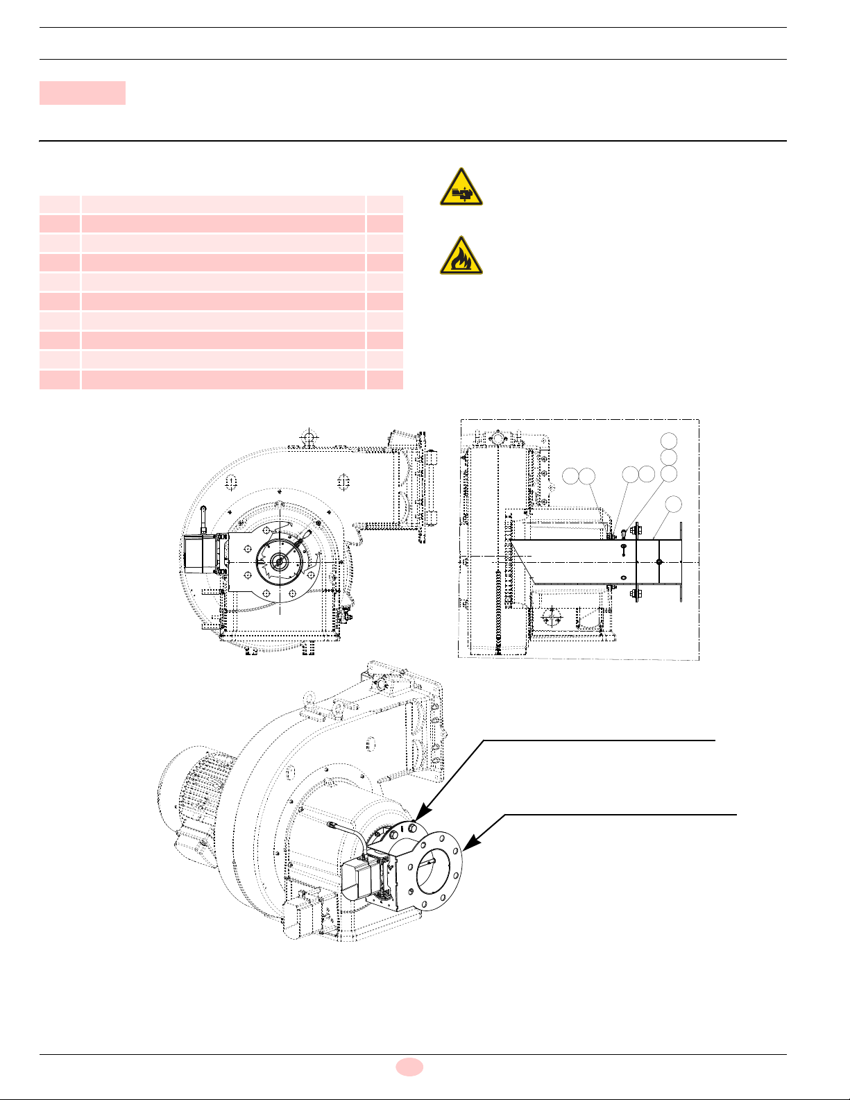
2.5 FGR duct system
– Normally the duct would connect to the stack as shown in
Fig. 7, with a 45° cut facing the flue gas flow and with the center
of the cut centered in the stack.
The duct could be made to the smoke box, but must still be lo-
cated with the same 45° cut facing the flue gas flow stream and
with the center of the cut in the center of the stream.
– The duct should be routed in a manner that has the minimum
number of elbows and provides for the normal expansion and
contraction of the piping.
Long duct runs can change length by over 1” and can put an
extreme load on the connecting points that could cause com-
ponent failures.
The design must include offsets that will allow for the required
movement of the piping without undue force on the burner or
stack.
– Duct expansion and contraction can be managed by using two
relatively long duct runs that are 90° opposed to each other.
A small movement in the angle between these two legs will pro-
vide the space needed to absorb the expansion and contrac-
tion. The ends of the FGR duct must be securely attached to
allow this to work properly, and prevent high loads from being
applied to the burner or stack.
– A condensation drip leg must be provided upstream of the FGR
control valve and the FGR shut-off valve (if used). There must
be sufficient condensate drip legs and catch space (volume of
drip legs) to prevent the condensation from flowing through the
control valves and into the fan.
In cases of heavy condensation, a condensate drip leg may be
required on the bottom of the housing, to remove condensate.
– Determine if pipe reducers are needed for the connection to the
FGR control valve and the FGR shut-off valve.
– The duct must be properly supported, handling both the weight
of the duct and to control the thermal expansion and contrac-
tion. The supports may need to be anchored to provide this sta-
bility in the FGR duct.
– The FGR duct is normally made from schedule 40 pipe be-
cause it is easily obtainable and inexpensive.
Schedule 20 pipe can also be used for this application.
– The duct components must be seal welded, flanged or screwed
together to provide an air tight duct.
Air leakage into the duct will prevent the system from working
properly. It is sufficient to only inspect the welds for a proper
seal, they do not need to be leak tested.
Key (Fig. 7)
1 Primary gas supply inlet
2 Inducted FGR modulating damper
3 Flue gas recirculation pipe
4 Boiler stack
5 Alternate Construction Using “T”
6 Burner
7Boiler
8 Drain Valve (Manual Ball Valve, Stainless Steel)
9 Drain line
10 Condensate Trap
Uncontrolled condensation can cause premature
failure of the control valves, fan and motor.
Adequate means must be provided to remove con-
densation from the system.
Cold start-up will generate significant amounts of
condensation.
D11299/S8367
1
2
3
3
4
76
8
9
10
5
8
8
Fig. 7