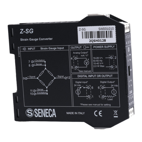
Seneca Z-SG2 User manual

User Manual
Z-SG2 / Z-SG2-L
ALL RIGHTS RESERVED. NO PART OF THIS PUBLICATION MAY
BE REPRODUCED WITHOUT PRIOR PERMISSION.
www.seneca.it
Doc: MI-005370-EN
Rev. 1.0.0.2
Page 2
Introduction
The content of this documentation refers to products and technologies described in it.
All technical data contained in the document may be changed without notice.
The content of this documentation is subject to periodic review.
To use the product safely and effectively, read the following instructions carefully before use.
The product must be used only for the use for which it was designed and manufactured: any other use is
under the full responsibility of the user.
Installation, programming and set-up are allowed only to authorized, physically and intellectually suitable
operators.
Set-up must be performed only after correct installation and the user must follow all the operations described
in the installation manual carefully.
Seneca is not responsible for failures, breakages and accidents caused by ignorance or failure to apply the
stated requirements.
Seneca is not responsible for any unauthorized modifications.
Seneca reserves the right to modify the device, for any commercial or construction requirement, without the
obligation to promptly update the reference manuals.
No liability for the contents of this document can be accepted.
Use the concepts, examples and other content at your own risk.
There may be errors and inaccuracies in this document that could damage your system, so proceed with
caution, the author(s) will not take responsibility for it.
Technical specifications are subject to change without notice.
CONTACT US
Technical support
Product information
Document revisions
DATE
REVISION
NOTES
AUTHOR
18/07/2019
1.0.0.0
First revision
MM
16/09/2019
1.0.0.1
Added info for bootloader
mode
Updated info for the USB port
Added a note for the Auto
Resolution
Added A Resolution Warning
MM
26/11/2019
1.0.0.2
Fix Status register
MM
This document is the property of SENECA srl.
Copies and reproduction are prohibited unless authorised.

User Manual
Z-SG2 / Z-SG2-L
ALL RIGHTS RESERVED. NO PART OF THIS PUBLICATION MAY
BE REPRODUCED WITHOUT PRIOR PERMISSION.
www.seneca.it
Doc: MI-005370-EN
Rev. 1.0.0.2
Page 3
TABLE OF CONTENTS
INTRODUCTION...........................................................................................................6
DESCRIPTION..........................................................................................................................................................................6
TECHNICAL SPECIFICATIONS ..............................................................................................................................................7
LED SIGNALS..............................................................................................................8
Z-SG2 / Z-SG2-L LED ..............................................................................................................................................................8
INSULATION ................................................................................................................8
POWER SUPPLY .........................................................................................................9
LOAD CELL CONNECTION.......................................................................................10
4 OR 6-WIRE LOAD CELL CONNECTION............................................................................................................................10
CHECKING THE LOAD CELL OPERATION .............................................................11
CHECKING CABLES WITH A DIGITAL MULTIMETER........................................................................................................11
CONNECTION OF MORE LOAD CELLS IN PARALLEL..........................................11
TRIMMING 4-WIRE LOAD CELLS ........................................................................................................................................13
DIGITAL OUTPUT / INPUT CONNECTIONS.............................................................14
ANALOGUE OUTPUT CONNECTIONS (Z-SG ONLY) .....................................................................................................14
RS485 PORT CONNECTIONS...............................................................................................................................................15
CONFIGURATION OF THE RS485 PORT BY DIP SWITCH.....................................17
CONFIGURATION OF THE FLASH MEMORY RS485 PORT...............................................................................................17
SETTING THE BAUD RATE OF THE RS485 PORT BY DIP SWITCH.................................................................................18
SETTING THE MODBUS STATION ADDRESS OF THE RS485 PORT BY DIP SWITCH...................................................19
SETTING THE R-C TERMINATOR BY SW3 DIP SWITCH ...................................................................................................20
COMPLETE CONFIGURATION WITH EASY SETUP............................................20
EASY SETUP MENU..............................................................................................................................................................20
CREATING A PROJECT........................................................................................................................................................21
OPERATING MODE......................................................................................................................................................21
10.2.1.1. FACTORY CALIBRATION ............................................................................................................................................21
10.2.1.2. CALIBRATION WITH SAMPLE WEIGHT .....................................................................................................................22
TYPE OF MEASUREMENT ..........................................................................................................................................22
10.2.2.1. COMPRESSION ONLY (SCALES) ...............................................................................................................................22
10.2.2.2. COMPRESSION AND TRACTION................................................................................................................................22
UNIT OF MEASUREMENT ...........................................................................................................................................22
CELL SENSITIVITY.......................................................................................................................................................22
CELL FULL SCALE .......................................................................................................................................................22

User Manual
Z-SG2 / Z-SG2-L
ALL RIGHTS RESERVED. NO PART OF THIS PUBLICATION MAY
BE REPRODUCED WITHOUT PRIOR PERMISSION.
www.seneca.it
Doc: MI-005370-EN
Rev. 1.0.0.2
Page 4
SAMPLE WEIGHT.........................................................................................................................................................22
NOISE FILTER ..............................................................................................................................................................22
FILTER LEVEL ..............................................................................................................................................................23
ADVANCED FILTERING...............................................................................................................................................23
10.2.9.1. NUMBER OF SAMPLES OF THE MOVING AVERAGE...............................................................................................23
10.2.9.2. ADC CHOPPING...........................................................................................................................................................23
10.2.9.3. ADC SPEED..................................................................................................................................................................23
10.2.9.4. NOISE VARIATION IN ADC POINTS ...........................................................................................................................24
10.2.9.5. FILTER RESPONSE SPEED ........................................................................................................................................24
NET WEIGHING RESOLUTION ...................................................................................................................................24
10.2.10.1. MAXIMUM RESOLUTION ........................................................................................................................................24
10.2.10.1. MANUAL...................................................................................................................................................................24
10.2.10.2. AUTOMATIC RESOLUTION ....................................................................................................................................24
DIGITAL INPUT/OUTPUT SELECTION........................................................................................................................25
DIGITAL INPUT CONFIGURATION..............................................................................................................................25
10.2.12.1. ACQUIRES THE TARE ............................................................................................................................................25
10.2.12.2. EXTERNAL DIGITAL INPUT ....................................................................................................................................25
DIGITAL OUTPUT OPERATION MODE.......................................................................................................................25
10.2.13.1. CELL FULL SCALE ..................................................................................................................................................25
10.2.13.2. EXCEEDING THE THRESHOLD AND STABLE WEIGHING ..................................................................................25
10.2.13.3. STABLE WEIGHING ................................................................................................................................................26
10.2.13.4. MODBUS CONTROLLABLE ....................................................................................................................................26
10.2.13.5. EXCEEDED THRESHOLD WITH HYSTERESIS (ALARM) .....................................................................................26
STABLE WEIGHING CONDITION ................................................................................................................................26
10.2.14.1. DELTA WEIGHT.......................................................................................................................................................27
10.2.14.2. DELTA TIME.............................................................................................................................................................27
NET WEIGHING ALARM ..............................................................................................................................................27
HYSTERESIS................................................................................................................................................................27
ANALOGUE OUTPUT TYPE ........................................................................................................................................27
10.2.17.1. VOLTAGE.................................................................................................................................................................27
10.2.17.2. CURRENT ................................................................................................................................................................27
ANALOGUE OUTPUT CONFIGURATION....................................................................................................................28
STATION ADDRESS.....................................................................................................................................................28
BAUD RATE ..................................................................................................................................................................28
PARITY..........................................................................................................................................................................28
DELAY IN REPLYING ...................................................................................................................................................28
SAMPLE WEIGHT.........................................................................................................................................................28
AUTOMATIC TARE TRACKER.....................................................................................................................................28
10.2.24.1. TARE TRACKER ......................................................................................................................................................28
10.2.24.2. ADC VALUE .............................................................................................................................................................28
FLOATING POINT REPRESENTATION OF THE MEASUREMENTS .........................................................................29
10.2.25.1. FIRST PART H THEN L ...........................................................................................................................................29
10.2.25.2. FIRST PART l THEN h .............................................................................................................................................29
DEVICE TEST.........................................................................................................................................................................29
THE DATA LOGGER ....................................................................................................................................................30
CALIBRATION OF THE LOAD CELL WITH THE EASY SETUP SOFTWARE .....30
FACTORY CELL CALIBRATION...........................................................................................................................................30
FACTORY CALIBRATION WITH TARE ACQUISITION FROM THE FIELD ........................................................................31
FACTORY CALIBRATION WITH MANUAL TARE ACQUISITION .......................................................................................31
User Manual
Z-SG2 / Z-SG2-L
ALL RIGHTS RESERVED. NO PART OF THIS PUBLICATION MAY
BE REPRODUCED WITHOUT PRIOR PERMISSION.
www.seneca.it
Doc: MI-005370-EN
Rev. 1.0.0.2
Page 5
CELL CALIBRATION WITH A SAMPLE WEIGHT ................................................................................................................32
USB PORT ..............................................................................................................33
DRIVERS FOR WINDOWS SYSTEMS ..................................................................................................................................34
DRIVERS FOR LINUX SYSTEMS..........................................................................................................................................34
FIRMWARE UPDATE..............................................................................................34
LOAD CELL CALIBRATION WITH MODBUS REGISTERS..................................35
CALIBRATION PROCEDURE WITH AN EXTERNAL DEVICE (FACTORY CALIBRATION WITH TARE ACQUIRED
FROM THE FIELD) ...............................................................................................................................................................................35
CALIBRATION PROCEDURE WITH AN EXTERNAL DEVICE (FACTORY CALIBRATION WITH MANUALLY INSERTED
TARE) 35
CALIBRATION PROCEDURE WITH AN EXTERNAL DEVICE (CALIBRATION WITH SAMPLE WEIGHT).......................35
MODBUS RTU SLAVE COMMUNICATION PROTOCOL ......................................36
SUPPORTED MODBUS FUNCTION CODES........................................................................................................................36
MODBUS REGISTER TABLE.................................................................................38
NUMBERING OF "0-BASED" OR "1-BASED” MODBUS ADDRESSES.............................................................................38
NUMBERING OF MODBUS ADDRESSES WITH "0-BASED" CONVENTION ............................................................39
NUMBERING OF MODBUS ADDRESSES WITH "1 BASED" CONVENTION (STANDARD)......................................39
BIT CONVENTION WITHIN A MODBUS HOLDING REGISTER ..........................................................................................40
MSB and LSB BYTE CONVENTION WITHIN A MODBUS HOLDING REGISTER..............................................................40
REPRESENTATION OF A 32-BIT VALUE IN TWO CONSECUTIVE MODBUS HOLDING REGISTERS ...........................40
TYPE OF 32-BIT FLOATING POINT DATA (IEEE 754)........................................................................................................41
Z-SG2/Z-SG2-L: MODBUS 4X HOLDING REGISTERS TABLE (FUNCTION CODE 3) ......................................................42

User Manual
Z-SG2 / Z-SG2-L
ALL RIGHTS RESERVED. NO PART OF THIS PUBLICATION MAY
BE REPRODUCED WITHOUT PRIOR PERMISSION.
www.seneca.it
Doc: MI-005370-EN
Rev. 1.0.0.2
Page 6
INTRODUCTION
ATTENTION!
This user manual extends the information from the installation manual to the configuration of the
device. Use the installation manual for more information.
ATTENTION!
In any case, SENECA s.r.l. or its suppliers will not be responsible for the loss of data/revenue or
consequential or incidental damages due to negligence or bad/improper management of the device,
even if SENECA is well aware of these possible damages.
SENECA, its subsidiaries, affiliates, group companies, suppliers and distributors do not guarantee that
the functions fully meet the customer's expectations or that the device, firmware and software should
have no errors or operate continuously.
DESCRIPTION
Z-SG2 is a load cell converter (strain gauge). The measurement, carried out with the 4 or 6-wire technique, is
available via the MODBUS-RTU serial protocol or via the fully configurable analogue output.
The device is equipped with a new noise filter specifically developed to obtain a rapid response time. The
device is fully configurable via the USB or RS485 ports using the Easy Setup configuration software.
Compared to its predecessor, it offers a new anti-noise filter and numerous new features, dramatically
increasing product performance.
Model
Description
Communication protocol
Z-SG2
Strain Gauge converter with digital
input/output and analogue output
Modbus RTU Slave
Z-SG2-L
Strain Gauge converter with digital
input/output
Modbus RTU Slave

User Manual
Z-SG2 / Z-SG2-L
ALL RIGHTS RESERVED. NO PART OF THIS PUBLICATION MAY
BE REPRODUCED WITHOUT PRIOR PERMISSION.
www.seneca.it
Doc: MI-005370-EN
Rev. 1.0.0.2
Page 7
TECHNICAL SPECIFICATIONS
Analogue/digital converter
24 Bit > of 16777000 points
Type of measurement
Unipolar ratiometric (compression only) or bipolar ratiometric
(compression and traction)
Noise digital filter
New advanced digital filter with configurable response time
from 16ms to about 2s.
Filter advanced configuration possibility.
Analogue output response time
About 5ms.
Modbus port (RS485) response time
About 6ms.
Net weight resolution
Configurable, factory-set on 10000 points (automatic).
Isolated analogue output resolution
10000 points
Operating mode
Calibration with sample weight (in the field) or without
calibration (factory calibration).
Isolated digital input/output
Yes, configurable between input/output.
USB port
Yes, on the front for the configuration, calibration, register
reading.
Drivers Virtual com port for Windows ™, Linux, MAC OS,
Windows CE
Configuration and calibration software
Easy Setup, free. For Windows operating systems.
Isolated digital input functions
Configurable between tare reset or external digital input.
Isolated digital output functions
Configurable in alarm mode:
- Cell bottom scale exceeded
- Threshold and stable weighing exceeded
- Stable weighing
- Generic output controlled by Modbus
- Threshold exceeded with hysteresis
Isolated analogue output (only Z-SG2)
Voltage/Current configurable.
Fully configurable on the 0-10V / 0-20mA range.
Firmware update
Yes for the addition of new functions.
Sensitivity
From +-1 mV/V to +-64 mV/V
“Stable weighing” function
Yes, configurable
Automatic tare tracker function
Yes, configurable
Piece counting function
Yes, configurable
“Manual tare” function
Yes, configurable. It does not need to acquire the tare value
from the field but it can be entered manually.

User Manual
Z-SG2 / Z-SG2-L
ALL RIGHTS RESERVED. NO PART OF THIS PUBLICATION MAY
BE REPRODUCED WITHOUT PRIOR PERMISSION.
www.seneca.it
Doc: MI-005370-EN
Rev. 1.0.0.2
Page 8
RS485 port baud rate
From 2400 to 115200 bit/s configurable
Parity, Delay in replying
Configurable
USB / RS485 port protocol
Modbus RTU Slave
LED SIGNALS
Z-SG2 / Z-SG2-L LED
LED SIGNALS ON THE Z-SG2 / Z-SG2-L FRONT
LED
STATUS
LED MEANING
PWR
ON
Device powered
PWR
OFF
Device OFF
ERR
ON
Corrupted Flash memory
RX
FLASHING
Data receipt on RS485 port
TX
FLASHING
Data sending on RS485 port
TX
ON
Check RS485 port connection
INSULATION

User Manual
Z-SG2 / Z-SG2-L
ALL RIGHTS RESERVED. NO PART OF THIS PUBLICATION MAY
BE REPRODUCED WITHOUT PRIOR PERMISSION.
www.seneca.it
Doc: MI-005370-EN
Rev. 1.0.0.2
Page 9
POWER SUPPLY
ATTENTION!
The upper power supply limits must not be exceeded, as this might cause serious damage to the
module
Switch the module off before connecting inputs and outputs.
To meet the electromagnetic immunity requirements:
- use shielded signal cables;
- connect the shield to a preferential instrumentation earth system;
- separate shielded cables from other cables used for power installations
(transformers, inverters, motors, induction ovens, etc...)
The power supply must be connected to terminals 20 and 21.
The supply voltage must be between:
10 and 40Vdc (indifferent polarity), or between 19 and 28 Vac.
19 –28 Vac 50 –60 Hz
10 –40 Vdc
Maximum absorption 2 W
If the ZPCDIN accessory is used, it is not necessary to wire the power supply (nor the RS485 port) as it is
present in the IDC10 connector:

User Manual
Z-SG2 / Z-SG2-L
ALL RIGHTS RESERVED. NO PART OF THIS PUBLICATION MAY
BE REPRODUCED WITHOUT PRIOR PERMISSION.
www.seneca.it
Doc: MI-005370-EN
Rev. 1.0.0.2
Page 10
LOAD CELL CONNECTION
It is possible to connect the converter to the load cell in 4- or 6-wire mode. 6-wire measurement is preferable
for measurement accuracy.
The load cell power supply is provided directly by Z-SG2.
4 OR 6-WIRE LOAD CELL CONNECTION
A load cell can have a four-wire or six-wire cable. In addition to having the +/- excitation and +/- signal lines a
six-wire cable also has the +/- sense lines. It is a common misconception to think that the only difference
between 4- or 6-wire load cells is the possibility of the latter to measure the actual voltage at the load cell. A
load cell is compensated to work within specifications in a certain temperature range (usually -10 - +40°C).
Since the cable resistance depends on the temperature, the response of the cable to temperature changes
must be eliminated. The 4-wire cable is part of the load cell temperature compensation system. The 4-wire
load cell is calibrated and compensated with a certain amount of cable connected. For this reason, never cut
the cable of a 4-wire load cell. The cable of a 6-wire cell, on the other hand, is not part of the load cell
temperature compensation system. The sense lines are connected to the sense terminals of the
indicator/meter, to measure and adjust the actual voltage of the load cell. The indicator/meter corrects the
output voltage or its amplifier to compensate for the change in resistance in the cable. The advantage of using
this "active" system is the possibility of cutting (or extending) the 6-wire load cell cable to any length. It must be
considered that a 6-wire load cell will not reach the performance declared in the specifications if the sense
lines are not used.
The figures show the two possible connections:

User Manual
Z-SG2 / Z-SG2-L
ALL RIGHTS RESERVED. NO PART OF THIS PUBLICATION MAY
BE REPRODUCED WITHOUT PRIOR PERMISSION.
www.seneca.it
Doc: MI-005370-EN
Rev. 1.0.0.2
Page 11
LOAD CELL CONNECTION
SIGNAL
TERMINAL
No.
MEANING
+Excitation
7
Cell supply (+)
+Sense
8
Reading of the supply to the cell (+)
+Signal
9
Load cell signal (+)
- Signal
12
Load cell signal (-)
- Sense
11
Reading of the supply to the cell (-)
- Excitation
10
Cell supply (-)
CHECKING THE LOAD CELL OPERATION
Before starting the configuration of the device it is necessary to verify the correctness of the wiring and the
integrity of the load cell.
CHECKING CABLES WITH A DIGITAL MULTIMETER
First you need to check with the load cell manual that there are about 5V DC between the +Excitation and –
Excitation cables. If the cell has 6 wires check that the same voltage is also measured between +Sense and –
Sense.
Now leave the cell at rest (without the tare) and check that the voltage between the +Signal and –Signal
cables is around 0 V.
Now unbalance the cell by applying a compression force, checking that the signal increases until it reaches the
full scale (if possible) where the measurement will be approximately:
5* (cell sensitivity) mV.
For example, if the declared cell sensitivity is 2 mV/V, 5 * 2 = 10 mV must be obtained.
In the case of bipolar measurement only (compression/traction) it is necessary to completely unbalance the
cell even in traction, in this case the same value must be measured between the +Signal and –Signal cables
but with the negative sign:
-5* (cell sensitivity) mV.
CONNECTION OF MORE LOAD CELLS IN PARALLEL
It is possible to connect up to a maximum of 8 load cells (and in any case without ever falling below the
minimum 87 Ohms). It is therefore possible to connect:

User Manual
Z-SG2 / Z-SG2-L
ALL RIGHTS RESERVED. NO PART OF THIS PUBLICATION MAY
BE REPRODUCED WITHOUT PRIOR PERMISSION.
www.seneca.it
Doc: MI-005370-EN
Rev. 1.0.0.2
Page 12
NUMBER OF LOAD CELLS IN PARALLEL
IMPEDANCE OF THE
STATED LOAD CELL
[Ohm]
MAXIMUM NUMBER OF CONNECTABLE CELLS IN PARALLEL
350
4
1000
8
For the connection of 4 load cells Seneca recommends using the SG-EQ4 product.
To connect 2 or more 4-wire cells in parallel with the SG-EQ4 junction box, use the following diagram:
To connect 2 or more 6-wire cells in parallel with the SG-EQ4 junction box use the following diagram:

User Manual
Z-SG2 / Z-SG2-L
ALL RIGHTS RESERVED. NO PART OF THIS PUBLICATION MAY
BE REPRODUCED WITHOUT PRIOR PERMISSION.
www.seneca.it
Doc: MI-005370-EN
Rev. 1.0.0.2
Page 13
For more details, refer to the SG-EQ4 Junction Box accessory manual.
TRIMMING 4-WIRE LOAD CELLS
The figure below shows a diagram of three trimmed load cells.
A variable resistor, independent of the temperature, or a typically 20 Ω potentiometer is inserted in the
+Excitation cable of each load cell. There are two ways to trim the load cells: The first method is to adjust the
potentiometers by trial, shifting the calibration weights from one corner to another. All the potentiometers must
be adjusted so as to set the maximum sensitivity for each cell, turning them all completely clockwise. Then,
once the angle with the lowest output is located, act on the trimmers of the other cells until obtaining the same
minimum output value. This method can be very long, especially for large scales where the use of test weights

User Manual
Z-SG2 / Z-SG2-L
ALL RIGHTS RESERVED. NO PART OF THIS PUBLICATION MAY
BE REPRODUCED WITHOUT PRIOR PERMISSION.
www.seneca.it
Doc: MI-005370-EN
Rev. 1.0.0.2
Page 14
on the corners is not very practical. In these cases the second, more suitable method is to "pre-trim" the
potentiometers using a precision voltmeter (at least 4 1/2 digits). You can use the following procedure:
1) Determine the exact mV/V ratio of each load cell, shown in the calibration certificate of the cell itself.
2) Determine the exact excitation voltage provided by the indicator/meter (for example Z-SG), measuring this
voltage with the voltmeter (for example 10.05 V).
3) Multiply the lowest mV/V value found (point 1) by the excitation voltage (point 2).
4) Divide the trimming factor calculated in point 3 by the mV/V value of the other load cells.
5) Measure and adjust the excitation voltage of the other three load cells using the respective potentiometer.
Check the results and make a final adjustment by moving a test load from corner to corner.
DIGITAL OUTPUT / INPUT CONNECTIONS
The device can be configured with a digital input or output.
The digital input can be configured to reset the tare if it is active for more than 3 seconds.
The digital output can be linked to a series of events (for example alarm on threshold, stable weighing etc ...).
In the case of configuration as a digital input or as a digital output, the connection diagram is as follows:
ANALOGUE OUTPUT CONNECTIONS (Z-SG ONLY)
The Z-SG device has an analogue output that can be configured for either voltage or current.
The operating ranges are 0-10V for the voltage output, 0-20 mA for the current output.
It is possible to freely configure the output in the entire range.
The wiring diagrams are:
Analogue voltage output:

User Manual
Z-SG2 / Z-SG2-L
ALL RIGHTS RESERVED. NO PART OF THIS PUBLICATION MAY
BE REPRODUCED WITHOUT PRIOR PERMISSION.
www.seneca.it
Doc: MI-005370-EN
Rev. 1.0.0.2
Page 15
Analogue current output:
RS485 PORT CONNECTIONS
The device has an RS485 serial port to be connected to the Z-PC-DINAL accessory and
therefore directly connected to the Seneca Z-PC range of devices:
Find below the pins for connector IDC10:

User Manual
Z-SG2 / Z-SG2-L
ALL RIGHTS RESERVED. NO PART OF THIS PUBLICATION MAY
BE REPRODUCED WITHOUT PRIOR PERMISSION.
www.seneca.it
Doc: MI-005370-EN
Rev. 1.0.0.2
Page 16
The protocol available through the RS485 port is Modbus RTU Slave.

User Manual
Z-SG2 / Z-SG2-L
ALL RIGHTS RESERVED. NO PART OF THIS PUBLICATION MAY
BE REPRODUCED WITHOUT PRIOR PERMISSION.
www.seneca.it
Doc: MI-005370-EN
Rev. 1.0.0.2
Page 17
CONFIGURATION OF THE RS485 PORT BY DIP SWITCH
The SW1 dip switch is used to configure the parameters related to the RS485 communication port.
DIP switches 1 and 2 are used for the baud rate of the RS485 port
DIP switches 3 to 8 are used for the Modbus station address of the RS485 port
ATTENTION!
The configuration via dip switch is active only after a restart!
ATTENTION!
The configuration via dip switch has priority over the one saved in flash, if you need to use the
configuration of the RS485 port sent by Easy Setup you must bring all the dip switches 1..8 to "OFF"
and restart the device.
CONFIGURATION OF THE FLASH MEMORY RS485 PORT
If ALL the dip switches 1 ... 8 are OFF, the device uses the configuration saved in Flash (configured with the
Easy Setup software) for the RS485 port.
RS485
configuration
DIP1
DIP2
DIP3
DIP4
DIP5
DIP6
DIP7
DIP8
FROM
FLASH
OFF
OFF
OFF
OFF
OFF
OFF
OFF
OFF

User Manual
Z-SG2 / Z-SG2-L
ALL RIGHTS RESERVED. NO PART OF THIS PUBLICATION MAY
BE REPRODUCED WITHOUT PRIOR PERMISSION.
www.seneca.it
Doc: MI-005370-EN
Rev. 1.0.0.2
Page 18
SETTING THE BAUD RATE OF THE RS485 PORT BY DIP SWITCH
Dip switches 1 and 2 configure the baud rate.
Baud Rate
DIP1
DIP2
9600
OFF
OFF
19200
OFF
ON
38400
ON
OFF
57600
ON
ON
ATTENTION !
The parity bit and other baud rates can only be configured via the Easy Setup software.
Setting the dip switches, parity will always be "No" and stop bits always at 1.

User Manual
Z-SG2 / Z-SG2-L
ALL RIGHTS RESERVED. NO PART OF THIS PUBLICATION MAY
BE REPRODUCED WITHOUT PRIOR PERMISSION.
www.seneca.it
Doc: MI-005370-EN
Rev. 1.0.0.2
Page 19
SETTING THE MODBUS STATION ADDRESS OF THE RS485 PORT BY DIP SWITCH
Dip switches 3 to 8 are used to configure the modbus station address of the RS485 port using the binary
convention:
Modbus
Station
Address
DIP3
DIP4
DIP5
DIP6
DIP7
DIP8
1
OFF
OFF
OFF
OFF
OFF
ON
2
OFF
OFF
OFF
OFF
ON
OFF
3
OFF
OFF
OFF
OFF
ON
ON
4
OFF
OFF
OFF
ON
OFF
OFF
5
OFF
OFF
OFF
ON
OFF
ON
6
OFF
OFF
OFF
ON
ON
OFF
7
OFF
OFF
OFF
ON
ON
ON
8
OFF
OFF
ON
OFF
OFF
OFF
9
OFF
OFF
ON
OFF
OFF
ON
10
OFF
OFF
ON
OFF
ON
OFF
11
OFF
OFF
ON
OFF
ON
ON
12
OFF
OFF
ON
ON
OFF
OFF
13
OFF
OFF
ON
ON
OFF
ON
14
OFF
OFF
ON
ON
ON
OFF
15
OFF
OFF
ON
ON
ON
ON
…
…
…
…
…
…
…
63
ON
ON
ON
ON
ON
ON
ATTENTION !
To set station addresses > 63 it is necessary to use the Easy Setup software.

User Manual
Z-SG2 / Z-SG2-L
ALL RIGHTS RESERVED. NO PART OF THIS PUBLICATION MAY
BE REPRODUCED WITHOUT PRIOR PERMISSION.
www.seneca.it
Doc: MI-005370-EN
Rev. 1.0.0.2
Page 20
SETTING THE R-C TERMINATOR BY SW3 DIP SWITCH
Usually it is not necessary to use a terminator on the RS485 line unless this is inserted into the bus by some
other device (for example some modbus masters have a terminator that cannot be removed).
Terminator
DIP SW3
OFF
OFF
ON
ON
COMPLETE CONFIGURATION WITH EASY SETUP
To configure the device it is necessary to install the free "Easy Setup" software suite which can be downloaded
in section Z-SG2/Z-SG2-L of the www.seneca.it website.
EASY SETUP MENU
Connect: Allows connecting the device to the PC.
New: Loads the default (factory) parameters onto the current project.
Open: Opens a previously saved project.
Save: Saves the current project
Read: Reads the current configuration from the device
Send: Sends the configuration (if the dip switches ARE NOT ALL OFF the device uses the configuration of the
RS485 by dip switch and NOT the one sent by the configuration)
Test and Calibration: Opens a new screen to read the main registers and allows you to send the commands
for the calibration of the load cell to the device.
This manual suits for next models
1
Table of contents
Other Seneca Media Converter manuals

Seneca
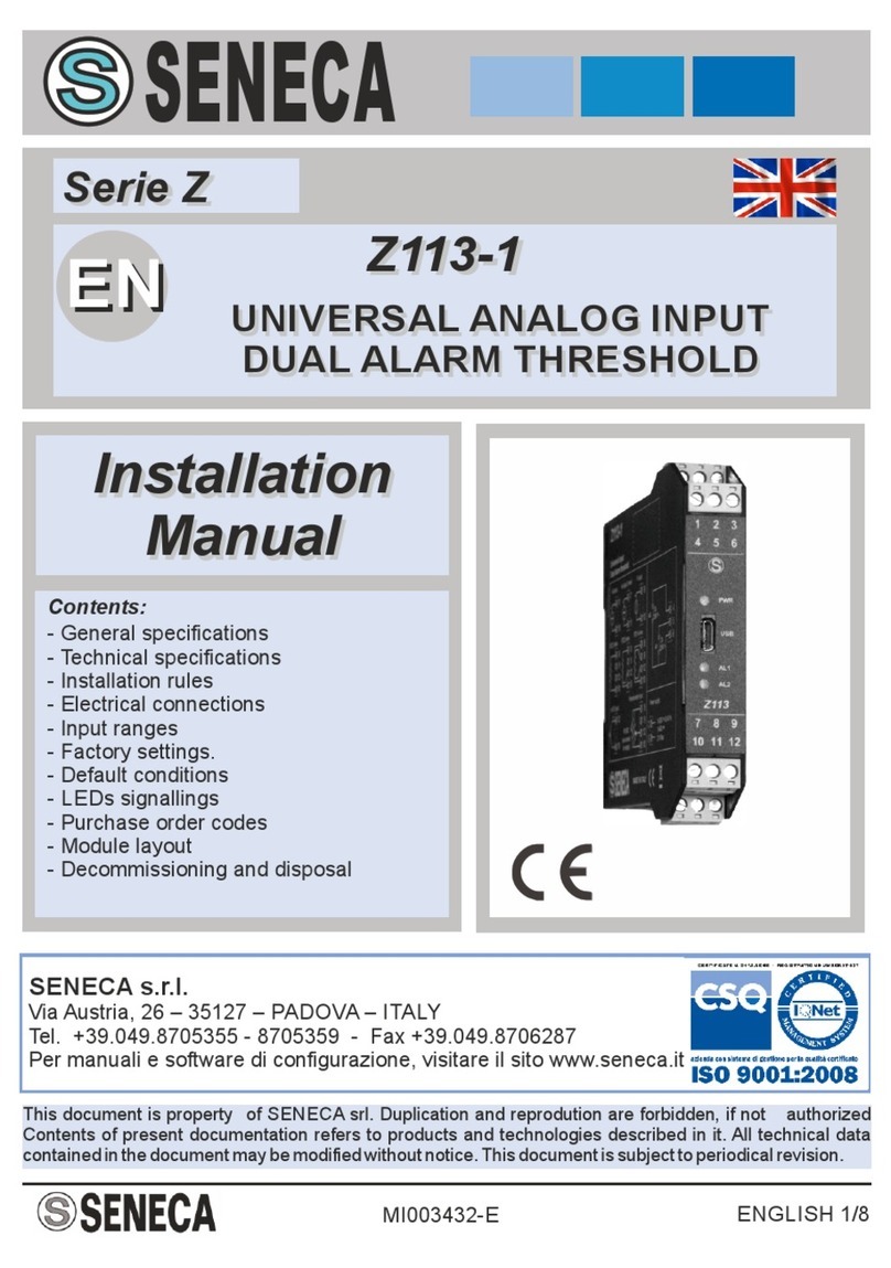
Seneca Z Series User manual

Seneca
Seneca Z-SG User manual

Seneca
Seneca S117P1 User manual

Seneca
Seneca K109S User manual

Seneca
Seneca Z-4RTD2 User manual

Seneca
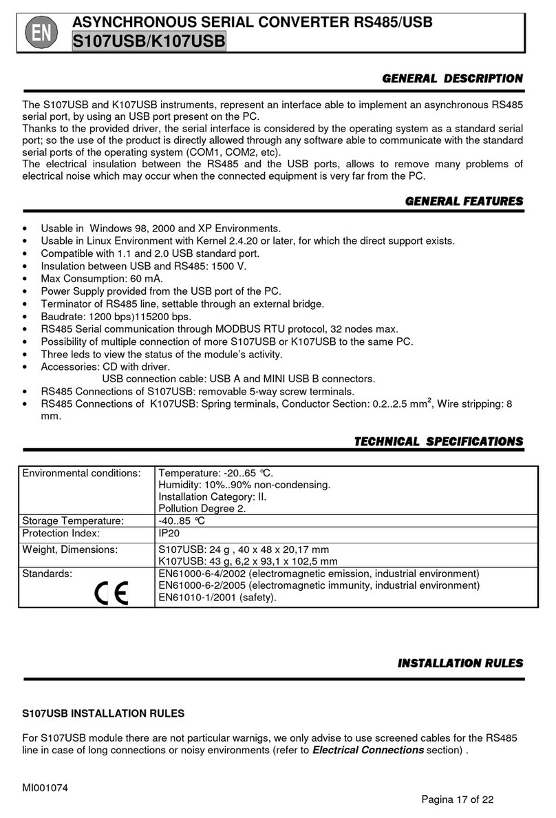
Seneca Z107 User manual

Seneca
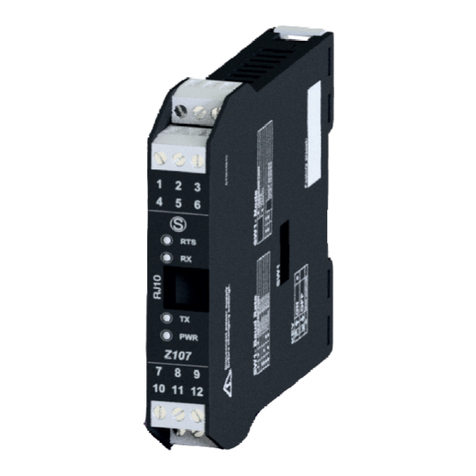
Seneca S107USB User manual

Seneca
Seneca ZC-SG User manual

Seneca
Seneca Z-SG3 User manual

Seneca
Seneca Z-MBus User manual

Seneca
Seneca Z109TC2-1 User manual

Seneca
Seneca S117P1 User manual

Seneca
Seneca Z Series User manual

Seneca
Seneca R-KEY-MBUS User manual

Seneca
Seneca Z-4RTD2-SI User manual

Seneca
Seneca Z109UI2 User manual

Seneca
Seneca Z111 User manual

Seneca
Seneca Z201 User manual

Seneca
Seneca Z-SG3 User manual

Seneca
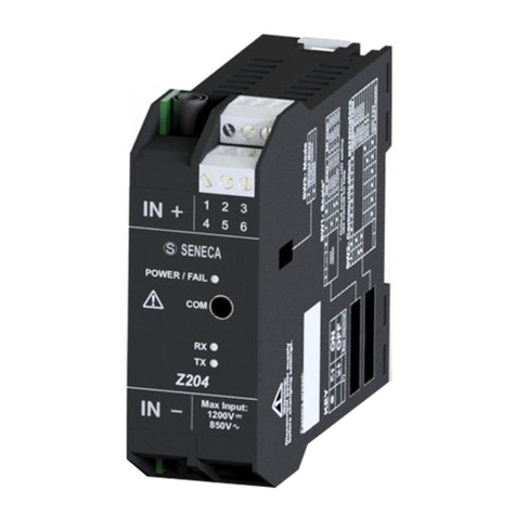
Seneca Z204-1 User manual