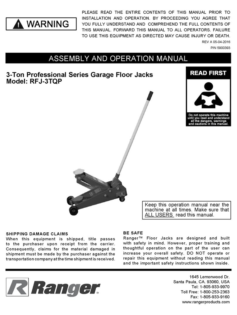
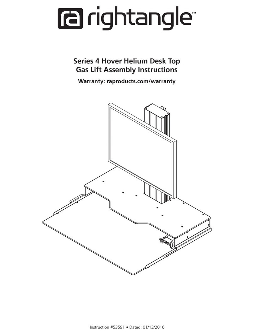
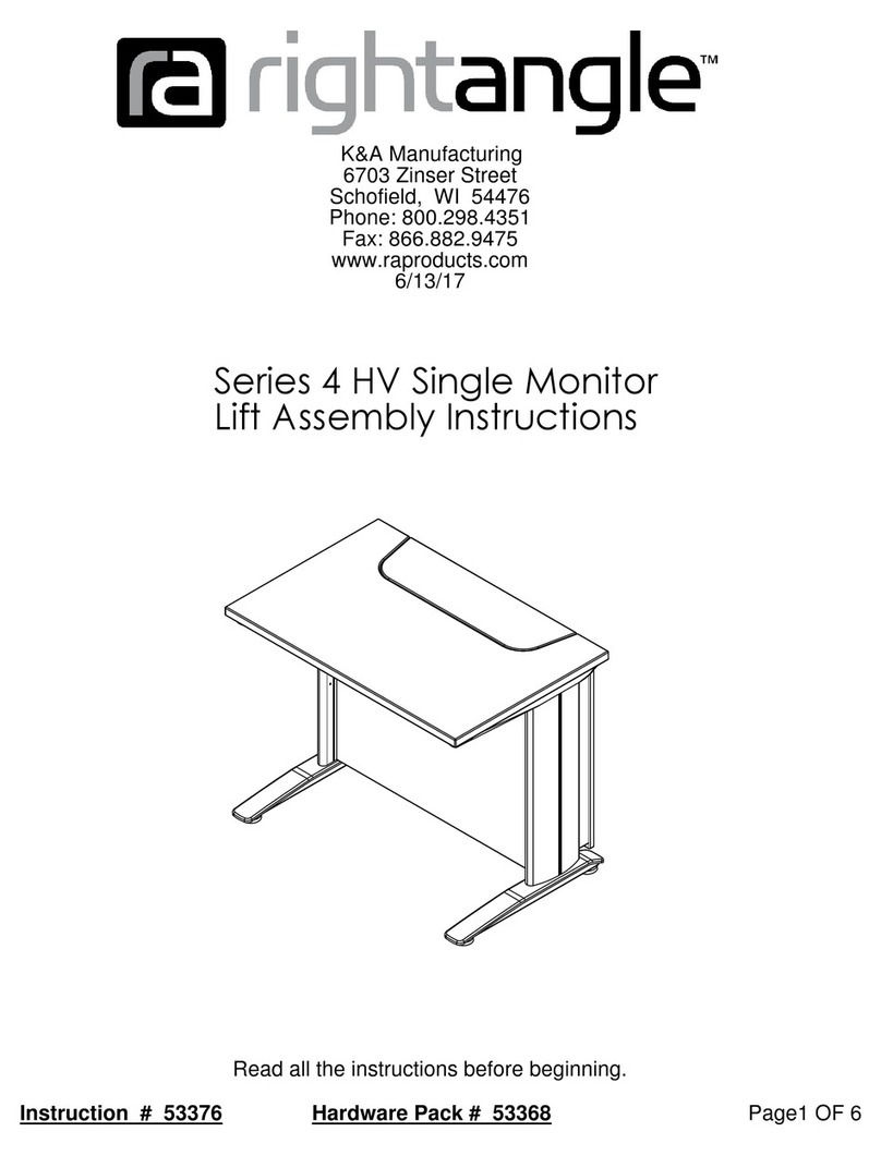
RIGHT ANGLE 4 HV Series User manual

Read all the instructions before beginning.
Hardware Pack # 53369
K&A Manufacturing
Page1 OF 8Instruction # 53375
Series 4 HV Double Monitor
Lift Assembly Instructions
6703 Zinser Street
Schofield, WI 54476
Phone: 800.298.4351
Fax: 866.882.9475
www.raproducts.com
7/14/17

12 13
Set them aside and slide them
Monitor Mounting Plate
plates after the workstation
Step 1
onto the monitor mounting
is fully assembled and upright.
16
Grommet Insert
15
Step 1: Attach the quick
connect monitor brackets 15
to your monitors with (4)
machine screws 16 in each.
915
1
www.raproducts.com
Tape Measure
Instruction # 53375
521275240651708
K&A Manufacturing
Phone: 800.298.4351
53360
Hardware Is Drawn Actual Size
Page 2 OF 8
5013351687
Square
Fax: 866.882.9475
6703 Zinser Street Schofield, WI 54476
Tools Required for Assembly:
Power Driver W/Adjustable Torque
#2 Phillips Head Driver Bit
Phillips Screwdriver
3/16" Hex Head Driver Bit or
Allen Wrench
Level
These Items Are
1/4 Actual Size.
14
16
17

ITEM # PART # DESCRIPTION QTY.
1 51687 5mm Slim Fix olt 24
2 52253 19mm Rafix Connector Cam 24
3 Varies HV Series 4 ack Panel 1
4 Varies HV Series 4 Kick Panel 1
5 WZRHVSPL HV Series 4 Side Panel Left 1
6 WZRHVSPR HV Series 4 Side Panel Right 1
7 Varies HV Series 4 Worksurface 1
8 801298 HV Series 4 Column Assembly 2
9 WZRHVTP HV Series 4 Top Panel 2
10 Varies Left Leg Assembly 1
11 Varies Right Leg Assembly 1
12 50133 10-32 x 1/2 Phillips Truss Head Machine Screw 22
13 51708 M5 x 18mm (7/8") Sq/Ph/Wshr Head Wood Screw 10
14 52406 M6-1 x 30mm Phillips Pan Head Machine Screw 6
15 53360 Quick Connect Monitor racket 2
16 52127 M4-7 x 10 Phillips Pan Head Machine Screw 8
17 Grommet Insert 2-3/8" Cable Grommet 4
Page 3 OF 8
K&A Manufacturing
6703 Zinser Street Schofield, WI 54476
Phone: 800.298.4351
Fax: 866.882.9475
www.raproducts.com
Instruction # 53376
Step 2: Using a power driver and a #2 phillips head
driver bit, drive (24) slim fix bolts 1into the back
panel 3, the kick panel 4, and the worksurface 7;
(8) in each panel.
Step 3: Using a phillips screwdriver, make sure that
all of the cams on the left side panel 5, the right
side panel 6, and the back panel 3are in the open
position (fully counter-clockwise).
Step 2
2
Loosen Counter-
Tighten Clockwise
Clockwise
Phillips Screwdriver
Cam Operation
Pre-installed
in Side Panels
& Kick Panel
(4)(4)
4
(4)
(4)
3
(3) (3)(2)
7

6703 Zinser Street Schofield, WI 54476
Fax: 866.882.9475
installation on the workstation later.
Page 4 OF 8
K&A Manufacturing
www.raproducts.com
Instruction # 53375
Phone: 800.298.4351
Step 4: Lay the column assemblies 8on the back panel 3as shown below.
Step 5: Attach the bottom bracket of the column assemblies 8to the back panel
3by screwing (8) machine screws 12 through the back of each bottom plate and
into the inserts in the back panel Do not fully tighten.
Step 6: Attach the top brackets to the back panel 3with (8) machine screws 12 as
you did on the bottom plate. Do not fully tighten.
Step 7: Attach the top panels 9to the worksurface supports with (5) wood screws 13
in each. Do not fully tighten.
Step 8: Square the top panels 9with the back panel 3and fully tighten all the wood
screws 13 holding the top panels to the worksurface supports. Square the column
assemblies 8 with the back panel and fully tighten the machine screws holding the
bottom plate and the side brackets to the back panel. Set the assembly aside for
Steps 4-8
12
3
TOP RACKET
9
13
12
8
OTTOM RACKET

6703 Zinser Street Schofield, WI 54476
Fax: 866.882.9475
Phone: 800.298.4351
K&A Manufacturing
Page 5 OF 8
Instruction # 53375
www.raproducts.com
Step 9: Lay the left leg assembly 10 on a protected
surface with the threaded screw holes facing up.
Attach the left side panel 5to the left leg assembly
with (3) machine screws 14 . The longer edge of the
side panel must face the back of the leg assembly.
Step 10: Repeat Step 9 with the right leg assembly 11
and the right side panel 6.
Step 11: Lay the worksurface 7on a protected
surface with the inserts facing up. Align the holes in
the left leg assembly 10 worksurface support with the
inserts in the worksurface, Attach the leg assembly to
the worksurface support with (3) machine screws 12 .
Do not fully tighten.
Step 12: Repeat Step 11 with the right leg assembly 11 .
10
5
Step 9 & 10
Back
14
Long
Edge
10
11
12
Steps 11 & 12
7
Worksurface
Support

Fax: 866.882.9475
www.raproducts.com
Instruction # 53375 Page 6 OF 8
K&A Manufacturing
6703 Zinser Street Schofield, WI 54476
Phone: 800.298.4351
Step 13: If your unit has power options, see Sheet 8.
Insert the (8) slim fix bolts 1in the kick panel 4into
the connector cams 2pre-installed in the left side
panel 5and the right side panel 6. You may need to
move the side panels slightly to align the bolts with the
cams.
Step 14: Insert the (8) slim fix bolts 1in the back panel
3into the connector cams 2pre-installed in the left side
panel 5and the right side panel 6. You may need to
move the side panels slightly to align the bolts with the
cams. Fully tighten all the camlocks in both side panels.
Important Note: When tightening the camlocks, they
will stop at a detent in the mechanism before they are
fully tightened. Be sure to tighten them past the detent.
Leveling Glide
monitor mounting plates until
Your workstation is now
ready for use.
they lock in place. See page 2.
4
5
Step 15: Make sure all the
panels are square and level.
Fully tighten the machine
screws 14 holding the side
panels 5and 6to the leg
assemblies 10 and 11 .
Fully tighten the machine
screws 12 holding the leg
assemblies to the work
surface 7 .
Step 16: With the help of an
assistant, set the workstation
upright in its final location.
Level the workstation if re-
quired by turning the leveling
glides clockwise ( from the top)
on the low corners of the unit.
If your workstation has casters,
level it by turning the bolts at
the top of the casters.
Step 17: Raise the top panels
9to their full height and slide
the monitors and the quick
connect brackets 15 onto the
6
9
14
3
12
shown for clarity.
Toe kick not
1
5
6
7
15

6703 Zinser Street Schofield, WI 54476
Fax: 866.882.9475
Phone: 800.298.4351
K&A Manufacturing
Page 7 OF 8
Instruction # 53375
www.raproducts.com
Step 18: Insert (4) grommet inserts 17 into the holes in
the kick panel 4. To operate the grommets, disassemble
the rotating inserts from the flange. Align one of the slots
in the inner insert with the slot in the outer insert. Run the
cables through the grommet flange. Reassemble the
grommet with the cables in the slots keeping the slots
pointed in the direction you want the cables to run.
17
4
Step 18
Flange
Inner Insert
17
Outer Insert

Table of contents
Other RIGHT ANGLE Lifting System manuals
Popular Lifting System manuals by other brands

Petermann
Petermann Alpha Lifting Seat manual

Sinoboom
Sinoboom 1414E Plus Operation manual

JLG
JLG T500J Service and maintenance manual

Harmar Mobility
Harmar Mobility AL600 Pioneer Installation and owner's manual

CAEL
CAEL 4PG8000 Installation and operation manual

HydroHoist
HydroHoist UltraLift FRONT MOUNT Series installation manual