Wabtec Ricon S Series User manual

Service Manual
09/30/10 32DSKE02.B.1 ©2010 RICON CORPORATION
All Rights Reserved
U.S. Patent Nos: 4,534,450; 5,228,538; 5,308,215; 5,373,915; 5,445,488; 5,605,431; 5,944,473; 6,043,741
Australia Patent Nos: 661127; 697066
Canadian Patent Nos: 1,245,603; 2,129,821; 2,168,761
German and U.K. EP0625896B1
Other U.S. and foreign patents pending
®
S-SERIES
AND K-SERIES
EXPORT USE WHEELCHAIR
AND STANDEE LIFT
S-Series™ K-Series™
TM
TM
-
Prin
t
-
-
Hom
e
-

i
TABLE OF CONTENTS
SEPTEMBER 2010
32DSKE02.B.1
S/K-SERIES EXPORT USE SERVICE MANUAL
This Ricon service manual is for use by qualified service techni-
cians, and is not intended for use by non-professionals (do-it-
yourselfers). The manual provides essential instructions and ref-
erence information, which supports qualified technicians in the
correct installation and maintenance of Ricon products.
Qualified service technicians have the training and knowledge to
perform maintenance work properly and safely. For the location of
a qualified service technician in your area, call Ricon Product
Support at 1-800-322-2884 or visit our website at
www.riconcorp.com.
Customer Name:
Installing Dealer:
Date Installed:
Serial Number:

ii
TABLE OF CONTENTS SEPTEMBER 2010
32DSKE02.B.1
S/K
-
SERIES EXPORT USE SERVICE MANUAL
REVISION RECORD
REV PAGES DESCRIPTION OF CHANGE ECO
32DSKE02.B.1
4-6 Illustration update to add item 7.
600025
4-7 Parts List update to add item 7.
4-12
4-13 Illustration update to add items 3, 4 & 5.
4-14 Parts List update to add items 2, 2A, 3, 3A, 4, 4A, 5, 5A.
4-18 Illustration update to add items 21 & 22.
4-19 Parts List update to add items 21 & 22.
4-20 Illustration update to add items 24, 25 & 26.
4-21 Parts List update to add items 24, 25 & 26.
4-22 Illustration update to add items 22 & 23.
4-23 Parts List update to add items 22 & 23.
END OF TABLE

iii
TABLE OF CONTENTS
SEPTEMBER 2010
32DSKE02.B.1
S/K-SERIES EXPORT USE SERVICE MANUAL
Chapter Page
I. INTRODUCTION ....................................................................................................................1-1
A. RICON PRODUCT SUPPORT........................................................................................................1-1
B. RICON PRODUCT WARRANTY.....................................................................................................1-2
C. SHIPMENT INFORMATION............................................................................................................1-3
D. GENERAL SAFETY PRECAUTIONS.............................................................................................1-3
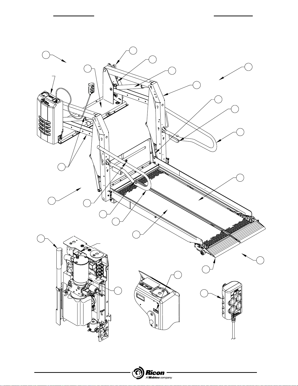
E. S-SERIES EXPORT USE MAJOR LIFT COMPONENTS...............................................................1-4
F. K-SERIES EXPORT USE MAJOR LIFT COMPONENTS ..............................................................1-6
II. INSTALLATION .....................................................................................................................2-1
A. MECHANICAL INSTALLATION .....................................................................................................2-1
1. LIFT LOCATION.........................................................................................................................................2-1
2. VEHICLE STRUCTURAL REQUIREMENTS ............................................................................................2-1
3. LIFT INSTALLATION GUIDELINES ..........................................................................................................2-1
4. LIFT INSTALLATION INTO VANS.............................................................................................................2-2
5. LIFT INSTALLATION INTO BUSES ..........................................................................................................2-5
B. ELECTRICAL INSTALLATION.......................................................................................................2-7
1. INSTALL MAIN CIRCUIT BREAKER.........................................................................................................2-8
2. ROUTE AND CONNECT MAIN POWER CABLE......................................................................................2-8
3. GROUND CONNECTIONS........................................................................................................................2-9
4. CONTROL PENDANT .............................................................................................................................2-10
5. INSTALLATION OF INTERLOCK DEVICE .............................................................................................2-11
C. FINAL ADJUSTMENTS ................................................................................................................2-12
1. LIMIT SWITCH ADJUSTMENT................................................................................................................2-12
2. PLATFORM TILT ADJUSTMENT............................................................................................................2-14
3. SPLIT PLATFORM TIE ROD ASSEMBLY INSTALLATION AND ADJUSTMENT.................................2-14.
4. K-SERIES PLATFORM FOLDING LINKAGE ADJUSTMENT.................................................................2-15
5. K-SERIES OUTER ROLLSTOP BARRIER ADJUSTMENT....................................................................2-16
6. PLATFORM PRESSURE SWITCH CHECK AND ADJUSTMENT..........................................................2-16
7. EMERGENCY RELEASE CABLE ADJUSTMENT..................................................................................2-18
D. VERIFY INSTALLATION...............................................................................................................2-19
III. MAINTENANCE AND REPAIR.............................................................................................. 3-1
A. LUBRICATION................................................................................................................................3-1
B. CLEANING......................................................................................................................................3-1
C. MAINTENANCE SCHEDULE..........................................................................................................3-2
D. TROUBLESHOOTING ....................................................................................................................3-3
1. LIFT TROUBLESHOOTING.......................................................................................................................3-3
2. LIFT TROUBLESHOOTING – ALARM WARNING INDICATOR...............................................................3-4
3. PUMP SOLENOID LED STATUS INDICATOR.........................................................................................3-5
4. BRIDGEPLATE CABLE ASSEMBLY REPLACEMENT.............................................................................3-5
5. S/K-SERIES LIMIT SWITCH STATES.......................................................................................................3-6
6. REAR SPRING REPLACEMENT ..............................................................................................................3-7
7. HYDRAULIC CYLINDER, GLAND NUT AND PISTON REPLACEMENT.................................................3-8
E. HYDRAULIC CIRCUIT DIAGRAM..................................................................................................3-9

iv
TABLE OF CONTENTS SEPTEMBER 2010
32DSKE02.B.1
S/K
-
SERIES EXPORT USE SERVICE MANUAL
F. ELECTRICAL WIRING DIAGRAM................................................................................................3-11
1. DIAGRAM LEGENDS.............................................................................................................................. 3-11
2. WIRING DIAGRAM.................................................................................................................................. 3-14
IV. PARTS DIAGRAMS AND LISTS........................................................................................... 4-1
Appendix: Lift Specifications..........................................................................................................4-29

1 - 1
I
N
TRODU
C
TIO
N
SEPTEMBER 2010
32DSKE02.B.1
S/K-SERIES EXPORT USE SERVICE MANUAL
I. INTRODUCTION
he Ricon S-Series™ and K-Series™ Export Use Wheelchair and Standee lifts provide wheelchair access to per-
sonal use vehicles. The patented movement on both models provides smooth, safe entry and exit and easily lifts
up to 363 kilograms (800 pounds). The platforms on both S- and K-Series Export Use Wheelchair lifts have a
rated load capacity of 363 kilograms (800 pounds).
The S-Series Export Wheelchair lift has two platforms options. One platform option splits and folds into the vehicle
when stowed and the other platform option is a solid, one-piece platform that is raised and folded into the vehicle when
stowed. The K-Series platform splits horizontally to reduce overall lift height when stowed. This results in a less ob-
structed view, either into or out of the vehicle. The mechanical linkages provide smooth movement to both non-skid
platforms where the wheelchair and occupant are situated during the “Up” and “Down” lift motions.
S- and K-Series Export Use Wheelchair lifts contain an electro-hydraulic pump with a built-in manual back-up pump and
an emergency release. If the lift loses power, it can be raised or lowered manually.
Trained personnel operate the lift by using a control pendant. The control pendant is used to unfold the platform out
from the vehicle (deploy). The passenger boards the non-skid platform and an operator lowers the platform to the
ground. After the passenger departs, the platform is stowed back into the vehicle.
This manual contains warranty information, safety precautions, optional configurations, operating and maintenance in-
structions that apply to both Ricon S- and K-Series Export Use wheelchair lifts. It is important to user safety that the lift
operator be completely familiar with the operating instructions. Once the lift is installed, it is very important that the lift
be properly maintained by following the Ricon recommended maintenance and inspection instructions provided in
Chapter III.
A. RICON PRODUCT SUPPORT
If you have questions about this manual, or additional copies are needed, please contact Ricon Product Support at one
of the following locations:
Vapor Ricon Europe Ltd.
Littlemoss Business Park
Littlemoss Road
Droylsden
Manchester, M43 7EF ........................................................................................+44 (0) 161 3016000
World Wide Website .......................................................................................www.RiconCorp.com
T

1 - 2
INTRODUCTION SEPTEMBER 2010
32DSKE02.B.1
S/K-SERIES EXPORT USE SERVICE MANUAL
B. RICON PRODUCT WARRANTY
®
RICON CORPORATION
FIVE-YEAR LIMITED WARRANTY
Ricon Corporation (Ricon) warrants to the original purchaser of this product that Ricon will repair or replace,
at its option, any part that fails due to defective material or workmanship as follows:
• Repair or replace parts for a period of two years from the date of purchase. A complete list of parts cov-
ered by this warranty can be obtained from Ricon Product Support.
• Labor costs for a period of two years from the date of purchase. A Vapor Ricon Europe rate schedule de-
termines parts covered and labor allowed.
• Repair or replace lift powertrain parts only for a period of five years from date of purchase. A complete
list of parts covered can be obtained from Vapor Ricon Europe product support.
If you need to return a product: Return this product to Ricon following the Ricon RMA procedure. Please
give as much advance notice as possible, and allow a reasonable amount of time for repairs.
This warranty does not cover: Malfunction or damage to product parts caused by accident, misuse, lack of
proper maintenance, neglect, improper adjustment, modification, alteration, the mechanical condition of the
vehicle, road hazards, overloading, failure to follow operating instructions, or acts of nature (i.e., weather,
lightning, flood).
Note: Ricon recommends that this product be inspected by an authorized Vapor Ricon Europe dealer or
qualified service technician at least once every six months or sooner if necessary. Any required maintenance
should be performed at that time.
WARNING
THIS PRODUCT HAS BEEN DESIGNED AND MANUFACTURED TO EXACT SPECIFICATIONS.
MODIFICATION OF THIS PRODUCT IN ANY RESPECT CAN BE DANGEROUS.
This warranty is void if:
• The product has been installed or maintained by someone other than an authorized Vapor Ricon Europe
dealer or qualified service technician.
• The product has been modified or altered in any respect from its original design without written authoriza-
tion by Vapor Ricon Europe or Ricon Corporation.
Ricon disclaims liability for any personal injury or property damage that results from operation of a Ricon prod-
uct that has been modified from the original Ricon design. No person or company is authorized to change the
design of this Ricon product without written authorization by Ricon.
Ricon's obligation under this warranty is exclusively limited to the repair or exchange of parts that fail within the
applicable warranty period.
Ricon assumes no responsibility for expenses or damages, including incidental or consequential damages.
Some states do not allow the exclusion or limitation of incidental or consequential damages, so the above limi-
tation or exclusion may not apply.
Important: The warranty registration card must be completed and returned to Ricon within 20 days after instal-
lation of this Ricon product for the warranty to be valid. The warranty is not transferable.
The warranty gives specific legal rights, and there may be other rights that vary from state to state.

1 - 3
I
N
TRODU
C
TIO
N
SEPTEMBER 2010
32DSKE02.B.1
S/K-SERIES EXPORT USE SERVICE MANUAL
C. SHIPMENT INFORMATION
• When the product is received, unpack the product and check for freight damage. Claims for any damage should be
made to the carrier immediately.
• Verify that the installation kit contains all items listed on the enclosed packing list. Please report any missing items
immediately to Ricon Product Support.
• The warranty and owner registration cards must be completed and returned to Ricon within 20 days to validate the
warranty.
NOTE: The Sales or Service personnel must review the Warranty and this Operator Manual with the user to be certain
that they understand how to safely operate the product. Instruct the user to follow the operating instructions
without exception.
D. GENERAL SAFETY PRECAUTIONS
The following general safety precautions apply to both S-Series and K-Series Export Use wheelchair lifts and must be
followed during installation, operation, and maintenance:
• Under no circumstances should installation, maintenance, repair, and adjustments be attempted without the imme-
diate presence of a person capable of rendering aid.
• An injury, no matter how slight, should always be attended. Always administer first aid or seek medical attention
immediately.
• Protective eyeshields and appropriate clothing should be worn at all times.
• To avoid injury, always exercise caution when operating and be certain that hands, feet, legs, and clothing are not
in the path of product movement.
• Batteries contain acid that can burn. If acid comes in contact with skin, flush affected area with water and wash with
soap immediately.
• Always work in a properly ventilated area. Do not smoke or use an open flame near a battery.
• Do not lay anything metallic on top of a battery.
• Check under vehicle before drilling to avoid drilling into frame, subframe members, wiring, hydraulic lines, brake flu-
id lines, fuel lines, fuel tank, etc.
• Read and thoroughly understand the operating instructions before attempting to operate.
• Inspect the product before each use. If an unsafe condition is noted, such as unusual noises or movements, do not
use lift until the problem is corrected.
• Never load or stand on the platform until installation is complete. Upon completion of installation, test load the lift to
100% of its rated load capacity.
• Stand clear of doors and platform and keep others clear during operation.
• The product requires regular periodic maintenance. Inspections are recommended at the intervals prescribed in
chapter three. The product must be maintained at the highest level of performance.

1 - 4
INTRODUCTION SEPTEMBER 2010
32DSKE02.B.1
S/K-SERIES EXPORT USE SERVICE MANUAL
E. S-SERIES™ EXPORT USE MAJOR LIFT COMPONENTS
The references used throughout this manual are illustrated in Figure 1-1 and defined in the Table 1-1. Refer to
Chapter IV “Parts Diagrams and Lists” for more details.
118
5
9
421
20
6
11
12
10
3
11
19
2
17
17
SEE DETAIL "A"
14
DETAIL "A" DETAIL "B"
(REAR VIEW) CONTROL
PENDANT
16
15
8
7
SEE DETAIL "B"
RSM0018102
13
FIGURE 1-1: S-SERIES EXPORT USE WHEELCHAIR LIFT MAJOR COMPONENTS

1 - 5
I
N
TRODU
C
TIO
N
SEPTEMBER 2010
32DSKE02.B.1
S/K-SERIES EXPORT USE SERVICE MANUAL
TABLE 1-1: S-SERIES EXPORT USE MAJOR COMPONENT TERM DEFINITIONS
REF NAME DESCRIPTION
1, 2,
3, 4 Left, Right,
Front, Rear Position references when the lift is viewed from outside of the vehicle.
5 Baseplate Bolts to vehicle floor; provides secure foundation for lift structure.
6 Bridgeplate
(inboard rollstop) Plate that bridges gap between platform and baseplate when platform is at
floor level. Also acts as a rear rollstop when platform is in motion.
7 Control pendant Hand-held device used to control platform motions.
8 Cycle counter Visible at top rear of housing, it records number of times platform has
moved from floor to ground and back to floor.
9 Emergency release
(Option) Enables emergency release mechanism that opens manual release valve
(located on hydraulic pump), disengages stow-lock latch (located on
baseplate) then allows platform to lower to ground level.
10 Front rollstop Front barrier prevents wheelchair from inadvertently rolling off of platform
during platform movement.
11 Handrail (left and right) Provides handhold for standing passenger.
12 Handrail light
(Option) (left and right) Directs light onto platform surface.
13 Remote Switch Remote controlled UP and DOWN switch.
14 Hydraulic cylinder (left and right) Telescoping single-acting cylinders convert hydraulic pres-
sure into platform lifting and folding force.
15 Hydraulic power unit Contains hydraulic pump driven by electric motor that produces pressure
to raise and fold platform, and a pressure release valve to unfold and lower
it.
16 Manual back-up
pump handle (located inside housing of hydraulic unit) Used to operate manual back-up
pump.
17 Platform Sections (left and right) Component of lift where the wheelchair and occupant are
situated during “UP” and “DOWN” lift motions.
18 Stow-Lock catch Engages latch located on bottom of bridgeplate when platform is fully
stowed.
19 Top and bottom arms (left and right) Upper and lower links that connect vertical arms to
baseplate.
20 Vertical arms (left and right) Connects platform to top and bottom arms.
21 Serial number Location of lift serial decal.
END OF TABLE

1 - 6
INTRODUCTION SEPTEMBER 2010
32DSKE02.B.1
S/K-SERIES EXPORT USE SERVICE MANUAL
F. K-SERIES™ EXPORT USE MAJOR COMPONENTS
The terms used throughout this manual are illustrated in Figure 1-2 and defined in Table 1-2. Refer to the parts dia-
grams and lists in Chapter IV for more details.
DETAIL "A"
16
15
SEE DETAIL "B"
DETAIL "B"
(REAR VIEW) CONTROL
PENDANT
1
23
5
9
420
14
22
6
12
13
11
3
10
21
8
7
2
19
18
17
SEE DETAIL "A"
RSM0018202
FIGURE 1-2: K-SERIES EXPORT USE WHEELCHAIR LIFT MAJOR COMPONENTS

1 - 7
I
N
TRODU
C
TIO
N
SEPTEMBER 2010
32DSKE02.B.1
S/K-SERIES EXPORT USE SERVICE MANUAL
TABLE 1-2: K-SERIES EXPORT USE MAJOR COMPONENT TERM DEFINITIONS
REF NAME DESCRIPTION
1, 2,
3, 4 Left, Right,
Front, Rear Position references when the lift is viewed from outside of the vehicle.
5 Baseplate Bolts to vehicle floor; provides secure foundation for lift structure.
6 Bridgeplate
(inboard rollstop) Plate that bridges gap between platform and baseplate when platform is at
floor level. Also acts as a rear rollstop when platform is in motion.
7 Control pendant Hand-held device used to control platform motions.
8 Cycle counter Visible at top rear of housing, it records number of times platform has
moved from floor to ground and back to floor.
9 Emergency release
(Option) Enables emergency release mechanism that opens manual release valve
(located on hydraulic pump), disengages stow-lock latch (located on
baseplate) then allows platform to lower to ground level.
10 Front platform
section Front portion of platform that unfolds during deploy and folds during stow.
11 Front rollstop Front barrier prevents wheelchair from inadvertently rolling off of platform
during platform movement.
12 Handrail (left and right) Provides handhold for standing passenger.
13 Remote Switch Remote controlled UP and DOWN switch.
14 Hydraulic cylinder (left and right) Telescoping single-acting cylinders convert hydraulic pres-
sure into platform lifting and folding force.
15 Hydraulic power unit Contains hydraulic pump driven by electric motor that produces pressure
to raise and fold platform, and a pressure release valve to unfold and lower
it.
16 Manual back-up
pump handle (located inside housing of hydraulic unit) Used to operate manual back-up
pump.
17 Platform folding
linkage (left and right) Links that cause front platform section to unfold as it
deploys or fold as it stows.
18 Platform hinges Three hinges provide connection between front and rear platform sections.
19 Rear platform section Rear portion of platform that is folded by linkage located within the vertical
arms.
20 Serial number Location of lift serial decal.
21 Top and bottom arms (left and right) Upper and lower links that connect vertical arms to
baseplate.
22 Vertical arms (left and right) Connects platform to top and bottom arms.
23 Stow-Lock catch Engages latch located on bottom of bridgeplate when platform is fully
stowed.
END OF TABLE

1 - 8
INTRODUCTION SEPTEMBER 2010
32DSKE02.B.1
S/K-SERIES EXPORT USE SERVICE MANUAL
This page intentionally left blank.

2 - 1
32DSKE02.B.1
INSTALLATIO
N
SEPTEMEBER 2010 S/K-SERIES EXPORT USE SERVICE MANUAL
II. INSTALLATION
his chapter contains instructions for installing the RICON S-Series™ and K-Series™ Export Use wheelchair lift
into most private use vehicles, although custom installations are also possible in other types of vehicles. Due to
the wide range of lift applications, specific information for every possible application is not available. The follow-
ing general procedures will apply to most installations. Contact Ricon Product Support for instruction concerning instal-
lations not covered. To install lift, refer to following sections and perform procedures carefully and in the order that they
are presented. Be certain that installation instructions are followed exactly and do not eliminate any steps or modify
product.
NOTE: Please review carefully the installation instructions (32ii427e) that are supplied with this lift before beginning the
following procedures. Where these procedures conflict, the installation instructions take precedence.
A. GENERAL MECHANICAL INSTALLATION
1. LIFT LOCATION
The installation surface must be flat and level. It is recommended that lift be installed on a 13mm (1/2 in.), mini-
mum, high-grade plywood sub-floor. However, this additional installation height may not be acceptable in cases
where overhead clearance is limited.
Refer to Figure 2-1.
NOTE: Check for proper travel clearance through doorway.
a. With doors fully open, place/position lift in vehicle doorway as close as possible to door, with lift's baseplate
assembly parallel to side of vehicle.
b. Allow a distance of 19mm (3/4 in.), if possible, between door and the part of lift closest to it. Adjust lift left
and right-side locations to accommodate subframe members.
c. Verify proper clearance of door frame, passenger seats, and outer edge of vehicle floor and possible inter-
ference with wires, fluid lines, subframe members, etc.
2. VEHICLE STRUCTURAL REQUIREMENTS
The following figures and text provide installation guidelines for the RICON S-Series and K-Series Export Use
wheelchair lift into most vehicles.
a. VEHICLE DOOR OPENING DIMENSIONAL REQUIREMENTS in millimeters and [inches].
MODEL A(Width) B(Height) C(Floor-To-Ground)
S1231 1029 [40.5] 1118 [44.0] 787 [31.0]
S2005 1080 [42.5] 1397 [55.0] 1067 [42.0]
S2030 1029 [40.5] 1397 [55.0] 1067 [42.0]
S2034 1029 [40.5] 1778 [70.0] 1067 [42.0]
K1200 1029 [40.5] 978 [38.5] 787 [31.0]
K2003 1029 [40.5] 1397 [55.0] 940 [37.0]
K2005 1080 [42.5] 1397 [55.0] 940 [37.0]
K2010 1130 [44.5] 1397 [55.0] 940 [37.0]
RSM0022501
A
B
C
VEHICLE FLOOR LEVEL
GROUND LEVEL
VEHICLE DOOR OPENING
FIGURE 2-1: DOOR OPENING REQUIREMENTS
T

2 - 2
INSTALLATIO
N
SEPTEMBER 2010
32DSKE02.B.1
S/K-SERIES SERVICE MANUAL
3. LIFT INSTALLATION GUIDELINES
The lift mounting is a very important step. Improper mounting or fastening of baseplate can adversely affect lift per-
formance. Although fastening details may vary from one vehicle to the next, these general principles apply:
♦Be certain that all mounting bolts are properly installed and tightened. Bolts used to fasten baseplate assembly
to vehicle floor must have a minimum strength rating of SAE Grade 5 and torque to 40 N-m (28 ft. lbs.), dry.
Recognize that the most important bolts are those along the rear of lift, since these bolts retain the majority of
the load.
♦Refer to Figures 2-2 and 2-6. Improper torque sequence of baseplate bolts may result in a warped or bowed
baseplate, which can cause platform to move erratically.
RSM0004800
CORRECT BOWED UP
TIGHTEN HERE
LOOSE N HERE TIGHTEN HERE
LOOSEN HERE
BOWED DOWN
FIGURE 2-2: VAN CLAMPING BAR ARRANGEMENT
♦Refer to Figure 2-3. On van installations, clamping bars are used to help evenly distribute floor loading and
should only be cut if needed to clear a subframe member. A subframe member must be used to support clamp-
ing bar.
RSM0004000
SUBFRAME MEMBER
CLAMPING BAR
MINIMUM UNSUPPORTED
CLAMPING BAR LENGTH
12”
CLAMPING BAR SUPPORTED BY
SUBFRAME WHERE POSSIBLE
VEHICLE FLOOR
FIGURE 2-3: VAN CLAMPING BAR ARRANGEMENT
4. LIFT INSTALLATION INTO VANS
This is a general procedure for installing Ricon lifts into full size vans.
a. Refer to Figure 2-4. Use four 25mm (1 in.) x 9.25mm (3/8 in.) bolts, 9mm (3/8 in.) washers, 9mm (3/8 in.)
lock washers, and 9mm (3/8 in.) hex nuts to assemble two bracket assembly kits.
NOTE: The top bracket must overlap bottom bracket, and both slots must face outward.

2 - 3
32DSKE02.B.1
INSTALLATIO
N
SEPTEMEBER 2010 S/K-SERIES EXPORT USE SERVICE MANUAL
RSM0004100
BOTTOM BRACKET
TWO PER BRACKETASSEMBLY
TOP BRACKET
(LEVEL WITH VEHICLE FLOOR)
VEHICLE FLOOR LEVEL
VEHICLE STEPWELL
FIGURE 2-4: STEPWELL BRACKET
b. Position brackets on stepwell and adjust height of both bracket assemblies so that top bracket is level with
vehicle floor. Tighten bracket assembly bolts.
c. Verify that lift is fully folded (stowed) with handrails folded tight against vertical arms. If necessary, use ma-
nual pump.
WARNING
LIFT WEIGHT IS APPROXIMATELY 154-179 KG (340 - 395 LBS.). USE EXTREME CARE WHEN
POSITIONING BECAUSE STEPWELL BRACKETS MAY TIP. THIS PROCEDURE MUST NOT BE
ATTEMPTED BY ONE PERSON.
d. Refer to Figure 2-5. With doors fully open, position lift in vehicle doorway so that back of lift is supported
by vehicle floor, and front of lift is supported by both bracket assemblies.
RSM0004200
BRACKETASSEMBLY
LIFT FRONT
VEHICLE FLOOR
LIFT REAR
FIGURE 2-5: BRACKET ASSEMBLY
e. Fasten Baseplate to vehicle floor:
NOTE: If Ricon power door operators are used, install them first. They may influence location of lift.
•Be certain baseplate is flush against vehicle floor. The baseplate may be slightly offset in door opening to
provide proper clearance for passenger seats.
•Before drilling, verify that lift position does not interfere with closing of vehicle doors or operation of passen-
ger seats.
•If this lift is being installed in a van with sliding doors, omit the bolts in baseplate holes 7 and 8.

2 - 4
INSTALLATIO
N
SEPTEMBER 2010
32DSKE02.B.1
S/K-SERIES SERVICE MANUAL
f. Mark and Drill Holes:
CAUTION
Before drilling holes, verify that underlying wires and tubing will not be damaged.
1) Refer to Figure 2-6. Mark and drill five 10mm (25/64 in.) baseplate mounting holes (1, 2, 3, 4, and 5)
through vehicle floor. CAUTION
Whenever possible, the maximum of ten bolts should be utilized to maintain
vehicle integrity and lift performance. It is the vehicle converter’s responsibility
to maintain vehicle integrity and lift performance should an impact occur.
2) Place five 203mm (8 in.) x 9mm (3/8 in.) carriage bolts into holes to secure position.
RSM0004300
FIGURE 2-6: VAN BASEPLATE HOLES
3) Refer to Figure 2-7. Match and align top holes of stepwell brackets 6, 7, 8, and 9, with baseplate holes
6, 7, 8, and 9. Mark lower stepwell bracket holes 10, 11, 12, and 13 onto vehicle step.
4) Remove five carriage bolts installed in step 2). Carefully push lift into vehicle interior.
5) Drill 6mm (1/4 in.) dia holes through marked locations 10, 11, 12, and 13.
RSM0004400
VEHICLE FRONT
VEHICLE REAR
FIGUR FIGURE 2-7: STEPWELL BRACKET HOLE LOCATIONS
g. Fasten Bracket Assemblies and Lift:
1) Use 38mm (1-1/2 in.) x 8mm (5/16 in.) sheet metal screws with 8mm (5/16 in.) lock washers to secure
lower brackets to vehicle step holes 10 through 13.
NOTE: If the screw in position 13 interferes with proper door operation, do not install.
2) Reposition lift and verify that surface beneath lift is free of obstacles.

2 - 5
32DSKE02.B.1
INSTALLATIO
N
SEPTEMEBER 2010 S/K-SERIES EXPORT USE SERVICE MANUAL
3) Insert five 203mm (8 in.) x 9mm (3/8 in.) carriage bolts through mounting holes at rear of baseplate as-
sembly, and insert four 138mm (1-1/2 in.) x 9mm (3/8 in.) carriage bolts through baseplate and bracket
assemblies. Place 9mm (3/8 in.) washers, lock washers, and nuts under bracket assemblies, and
hand-tighten nuts.
4) Before tightening carriage bolts, verify that lift is level with vehicle floor. Adjust bracket assembly bolts if
necessary.
5) Tilting lift towards inside of van may hinder its initial unfolding. Install lift with its baseplate assembly as
level as possible. Tightening carriage bolts requires special care to keep baseplate assembly from
warping when secured to vehicle floor. If baseplate assembly warps, the vertical arms will not be paral-
lel. Make corrections by shimming at appropriate locations. To help prevent warping, tighten the eight
carriage bolts (six on van with sliding door) to 40 N-m (28 ft. lbs.) in the appropriate sequence:
VANS WITH SWING DOORS ........................................................... 3, 1, 2, 4, 5, 6, 7, 8, 9
VANS WITH SLIDING DOORS ..................................................................3, 1, 2, 4, 5, 6, 9
NOTE: Vertical arms must be parallel for proper operation. Adjust bolts as required. Best results are obtained
when lift is mounted on plywood. Shims, although best avoided, may be used if required.
6) Make certain that holes 14 and 15 on the front of each bracket assembly are drilled through, and 8mm
(5/16 in.) bolts are inserted to lock position of bracket assemblies.
5. LIFT INSTALLATION INTO BUSES
Refer to Figure 2-8. Clamping bars are used on most bus installations to help distribute floor loading, and should
only be cut if needed to clear a subframe member. A subframe member should be used to support clamping bar.
RSM0004500
12”
VEHICLE FLOOR
SUBFRAME MEMBER
CLAMPING BAR
MINIMUM UNSUPPORTED
CLAMPING BAR LENGTH
CLAMPING BAR SUPPORTED BY
SUBFRAME WHERE POSSIBLE
FIGURE 2-8: BUS CLAMPING BAR ARRANGEMENT
WARNING
LIFT WEIGHT IS APPROXIMATELY 154-179 KG (340 - 395 LBS.). TAKE EXTREME CARE WHEN
POSITIONING BECAUSE STEPWELL BRACKETS MAY TIP. THIS PROCEDURE MUST NOT BE
ATTEMPTED BY ONE PERSON.
a. Open doors fully and position lift so that it is centered in vehicle doorway. Close doors and move lift out-
ward until it clears doors by a minimum of 13mm (1/2 in.). The baseplate must be parallel to side of bus.
Open manual pump release valve (CCW) and allow folded platform to fully settle against latch on basep-
late. Verify that interference is not present between lift and doors. Reposition lift, if necessary. Close
pump release valve; do not over tighten valve.
b. Refer to Figure 2-9. Mark and drill ten 10mm (25/64 in.) baseplate mounting holes (1 thru 10) through ve-
hicle floor.

2 - 6
INSTALLATIO
N
SEPTEMBER 2010
32DSKE02.B.1
S/K-SERIES SERVICE MANUAL
RSM0004600
FIGURE 2-9: BUS BASEPLATE HOLES
CAUTION
Before drilling holes, verify that underlying wires and tubing will not be damaged.
c. Fasten Lift:
1) Insert ten 101mm (4 in.) x 9mm (3/8 in.) carriage bolts through baseplate and vehicle floor.
2) Refer to Figure 2-9. Install five clamping bars on bolts underneath vehicle floor (across baseplate), i.e.,
from 1 to 6, 2 to 7, etc, and secure lift to vehicle floor with 9mm (3/8 in.) washers, lock washers and
hex-nuts.
3) Use care when tightening carriage screws to prevent baseplate warpage. If baseplate assembly warps,
vertical arms will not be parallel. Make corrections by shimming at appropriate locations. To help pre-
vent warping, torque the eight carriage bolts to 40 N-m (28 ft. lbs.) in the following sequence:
3, 8, 2, 4, 7, 9, 1, 5, 6, 10
NOTE: Vertical arms must be parallel for proper operation. Adjust bolts as required. Best results are obtained
when lift is mounted on plywood. Shims, although best avoided, may be used if required.

2 - 7
32DSKE02.B.1
INSTALLATIO
N
SEPTEMEBER 2010 S/K-SERIES EXPORT USE SERVICE MANUAL
B. ELECTRICAL INSTALLATION
CAUTION
•Do not route any wire while it is connected to the battery.
•Route wires clear of moving parts, brake lines, and the exhaust system. Secure to the vehicle.
•When routing an electrical wire through vehicle floor or walls, use a grommet to protect wires from chafing.
•Check underside of vehicle before drilling to avoid damage to fuel lines, vent lines, brake lines, or wiring.
GROUND STRAP
ROUTED BEHIND
MOTOR
RSM0020302
30AMP CIRCUIT BREAKER
8 AMP CIRCUIT BREAKER
MAIN POWER HARNESS
CONNECTED TO
TOP OF PUMP MOTOR
MAIN POWER HARNESS
CONNECTED TO
12V SOLENOID
PUMPASSEMBLY
CHASSIS
37mm (1.45 in.) W BUSBAR (X2)
GROUND STRAP
CONNECTED TO
VEHICLE CHASSIS
12V SOLENOID (X2)
MINI-FIT CONNECTORS
POSITIVE CONNECTION
BLOCK
4 AWG POWER CABLE
SHORT CABLE, NOT TO EXCEED 305mm (12 in.),
CONNECTED BETWEEN BATTERY (OR
MAIN POWER SOURCE)AND
CIRCUIT BREAKER
4 AWG POWER CABLE
LONG CABLE CONNECTED BETWEEN
MAIN CIRCUIT BREAKER AND POSITIVE
CONNECTION BLOCK
100AMP
MAIN CIRCUIT
BREAKER
4 GA GROUND CABLE
TO BATTERY TERMINAL
FIGURE 2-10: ELECTRICAL INSTALLATION DIAGRAM
Other manuals for Ricon S Series
4
This manual suits for next models
9
Table of contents
Other Wabtec Lifting System manuals

Wabtec
Wabtec R-290 User manual

Wabtec
Wabtec Ricon TITANIUM S Series User manual

Wabtec
Wabtec Ricon K Series User manual

Wabtec
Wabtec R-150 User manual

Wabtec
Wabtec Ricon S Series User manual

Wabtec
Wabtec Ricon S Series User manual

Wabtec
Wabtec Ricon FoldOver FR2SS Series User manual

Wabtec
Wabtec Ricon S Series User manual
Popular Lifting System manuals by other brands

Ravas
Ravas iForks Service manual

Norco
Norco 82304 Setup, operating, maintenance instructions

National ramp
National ramp FREEDOM Series Instructions and warnings

ATH-Heinl
ATH-Heinl Four Lift 55P user manual

VMB
VMB TL - A320 instruction manual

Dover
Dover Environmental Solutions BAYNE TL 1128 Operation and parts manual