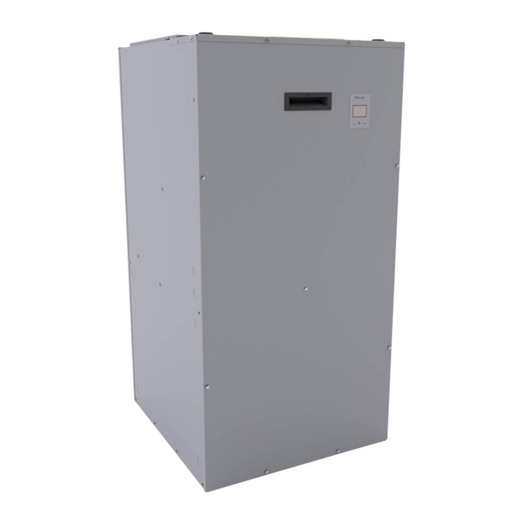
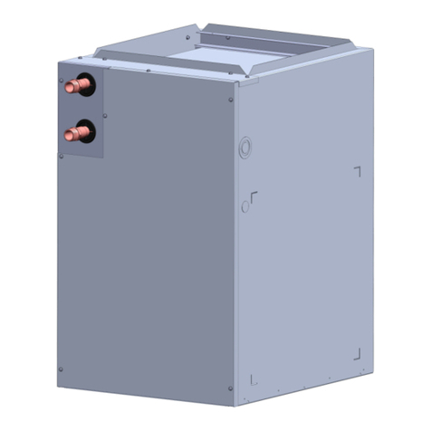
Rinnai 37AHA Series Installation guide

37AHA SERIES
HYDRONIC AIR HANDLER
SIZES 045 THRU 090
TrainingManual
The Rinnai Tankless Heating System................... 2
Installation Codes and Standards ......................... 2
Model Number Nomenclature................................ 3
Features............................................................. 4, 5
Performance Specification Summary.................... 6
Inside the Hydronic Air Handler............................. 6
Basic Sequence of Operation...........................7-10
Specifications ...................................................... 11
Installation Configurations.............................12, 13
Multi-Position Orientation .............................. 14, 15
Suspended Cabinet Installation........................... 16
Duct Connections / Air Distribution Ductwork...... 17
Plumbing.............................................................. 18
Accessories ....................................................19-25
Electrical Connections......................................... 26
Dip Switch Options .............................................. 27
Purging and Priming the System......................... 28
Maintenance........................................................ 29
Troubleshooting................................................... 30
Warranty.............................................................. 31
Sample Installation .............................................. 32
Rinnai Tankless Water Heater Sizing............33, 34
Sizing Example.................................................... 35
Parts List........................................................ 36, 37
Product Knowledge Test ..................................... 38
The Rinnai Hydronic Air Handler
(A key component of the Rinnai
Tankless Heating System)

2 Rinnai Corporation Hydronic Air Handler 101 Training Manual
Installation Codes and Standards
The Rinnai Tankless Heating System
The Hot Way to Heat Your Home –
The Tankless Heating System combines the Rinnai tankless water heater and a new
hydronic air handler to provide comfortable residential heat. Now the energy savings
and endless hot water of a Rinnai tankless water heater can be applied to heating both
residential air and water.
How it Works –
The hydronic air handler connects to a Rinnai tankless water heater through normal
plumbing lines. When there is a call for heat, the air handler pump activates and begins
to circulate water between the air handler and the water heater. The hot water runs
through a copper tube/aluminum fin coil mounted above a blower, which drives air
through the coil and into the ductwork, providing comfortable, warm, hydronic heat that
can’t be matched by gas furnaces or heat pumps.
Product Codes and Standards
All national codes, standards and local ordinances must be adhered to in addition to the
instructions accompanying each product. The installation must comply with regulations
of the local building, heating, plumbing and other codes. Where local codes are not
applicable, the installation must comply with national codes and any and all authorities
having jurisdiction.
Suggested Codes and Standards for the United States and Canada:
General Installation –
Installation of Air Conditioning and Ventilating Systems NPFP 91
Duct Systems –
Sizing of duct system to be performed prior to product installation
Sheet Metal and Air Conditioning Contractors National Association (SMACNA)
American Society of Heating, Refrigeration, and Air Conditioning Engineers (ASHRAE)
Fundamentals Handbook Chapter 34 or HVAC Systems and Equipment Handbook
Chapters 9 and 16
US and CANADA; Air Conditioning Contractors Association (ACCA) Manual D
Acoustical Lining and Fibrous Glass Duct
US and CANADA; current edition of SMACNA; NFPA 90B as tested by UL Standards
181 for Class I Rigid Air Ducts
Electrical Connections
US: National Electrical Code (NEC) ANSI/NFPA 70.
CANADA: Canadian Electrical Code CSA C22.1
Plumbing Systems
US and CANADA: ICC International Plumbing Code (IPC); Uniform Mechanical Code
(UMC); Uniform Plumbing Code (UPC)

Rinnai Corporation Hydronic Air Handler 101 Training Manual 3
Model Number Nomenclature
37AH A 045 08 K A 5 Multi-position
5 = Yes
2 = No
Engineering Digit
Denotes minor change
(not present in sales or service
literature)
Voltage Code (V-Ph-HZ)
K = 115 - 1 - 60
L = 240 - 1 - 50 (export models)
Model
37AH - Multi-speed Hydronic Air Handler
Series
Denotes a major design change in the
product line (i.e. capacity)
Nominal Heating Capacity (BTU/h)
045 = 45,000
060 = 60,000
075 = 75,000
090 = 90,000
Cooling / Heating Air Flow Range (CFM)
08 = 800 (650-800)
12 = 1200 (650-1200)
14 = 1400 (1000-1600)
16 = 1600 (1200-1750)

4 Rinnai Corporation Hydronic Air Handler 101 Training Manual
Domestic Hot Water Priority
The Rinnai Hydronic Air Handler includes* a domestic hot water priority flow sensor that
will determine when to shut down and re-direct all the water heater’s output to whichever
fixture and or appliances that are calling for hot water. This feature will turn off the pump
to prevent cold air from blowing into the structure and excessive wear on the internal
pump components.
* The flow sensor is to be installed at the site
–Four models covering nominal heating sizes from 45,000 to 90,000 BTU/hour
–Multi-position (upflow, downflow, horizontal left, horizontal right)
• Modifiable for side-entry return air
• NOTE: the unit is not designed to be installed on its back.
–Low-flow, high-head pump designed to work with Rinnai’s tankless water heaters
–No combustion air infiltration losses when used with a Rinnai tankless water heater
–Four selectable heat blower-off delay times – adjustable fan speeds provide
operational efficiency of heat distribution with 30, 60, 90 and 120 second blower
off settings
–Multi-speed motor
•800 – 1600 Nominal Heating Airflow (CFM)
•Adjustable to meet the needs of the heating and cooling CFM blower
requirements
–Strong steel cabinet
•Pre-painted galvanized steel
Features
AH45 AH60 AH75 AH90

Rinnai Corporation Hydronic Air Handler 101 Training Manual 5
Features •Fully insulated with foil lining
•Low 34-inch profile on all models
–Multi-position electrical junction box. The junction box will mount on either side of
cabinet to adapt to the installation requirements
–Designed for serviceability with removable front panel to obtain access to pump,
blower and control board
–Schrader valve integrated into air handler coil to manually purge air from the system
–Side filter rack (option)
–Control board connections for:
• Electronic Air Cleaner (EAC)
• Humidifier (HUM)
• UV Lamp (UV & N4)
–Intelligent Microprocessor Control
• The Hydronic Air Handler units are equipped with an intelligent microprocessor
control that allows for domestic hot water priority and adapts to available hot water
flow for space heating by automatically regulating the pump and fan sequence to
maximize comfort.
• During the non-heating season, the microprocessor will cycle the pump every six
hours (for two minutes) to prevent the water in the system from becoming stagnant.
The microprocessor will adapt to the domestic hot water usage schedule to ensure
this maintenance cycle will not come on when there is a call for domestic hot water.
During the maintenance cycle, the microprocessor prevents the blower from
operating to prevent dispersing hot air. This process will also cycle during the
cooling season.
–Fine-Tuned to Work with Rinnai Tankless Water Heaters
• The unique hydronic air handlers are designed to work in combination with Rinnai
tankless water heaters to deliver a wide variety of heating capacities that cover a
broad range of residential and light commercial heating spectrums. Because of the
matched system, Rinnai Hydronic Air Handlers are not designed to be installed with
any other tank, tankless or boiler product.
• The resulting Tankless Heating System is the only matched tankless hydronic
solution within the industry!

6 Rinnai Corporation Hydronic Air Handler 101 Training Manual
Performance Specification Summary
*All heating outputs based on 68°return air
External Static Pressure based on 0.5” W.C. without Evaporator Coil
Foil-Faced Insulated Cabinet
Coil Assembly
Hydronic Pump
Blower Assembly (multi-speed motor)
Control Box and Control Board
Filter
Inside the Rinnai Hydronic Air Handler
Model Heating
CFM
Water Temperature
Nominal Heating Outputs (BTU/h) CFM
RANGE
Tons (A/C
or Heat
Pump)
Weight
120°130°140°150°160°
AH45 800 28,000 33,750 39,500 45,000 51,000 650-800 1.5 - 2.0 92 107
AH60 1200 37,500 45,000 52,500 60,000 68,000 650-1200 1.5 - 3.0 109 127
AH75 1400 46,000 55,500 65,000 75,000 84,500 1000-1600 2.5 – 4.0 118 138
AH90 1600 55,000 65,250 77,500 90,000 101,000 1200-1750 3.0 – 5.0 136 159
Shipping
Installed

Rinnai Corporation Hydronic Air Handler 101 Training Manual 7
Basic Sequence of Operation
• The thermostat calls for heat and engages air handler pump creating water flow
• The Rinnai tankless water heater fires and begins heating
• The air separator ensures the circulation loop is purged
• Hot water passes through the hydronic heating coil
• After 25 seconds of pump operation, the blower moves heated air into the structure
• Water continues to circulate through the tankless water heater and hydronic heating coil as
long as there is a call for heat
• Water also flows to domestic hot water fixtures if there is demand. An installed tempering
valve reduces the potential of scalding
Typical Open-Loop Air Handler Operation

8 Rinnai Corporation Hydronic Air Handler 101 Training Manual
Basic Sequence of Operation
• The thermostat calls for heat and engages air handler pump creating water flow
• The Rinnai tankless water heater fires and begins heating
• The air separator ensures the circulation loop is purged
• Hot water passes through the hydronic heating coil
• After 25 seconds of pump operation, the blower moves heated air into the structure
• Water continues to circulate through the tankless water heater and hydronic heating coil as
long as there is a call for heat
• Water also flows to domestic hot water fixtures if there is demand. An installed tempering
valve reduces the potential of scalding
• If domestic demand increases to effect heating capability, the air handler flow sensor sends
signal to turn pump and blower off until domestic flow has decreased
• When the air handler pump stops (either due to domestic demand or a satisfied thermostat),
the blower will continue for 30, 60, 90, or 120 seconds depending on preferred settings
Typical Open-Loop Air Handler Operation

Rinnai Corporation Hydronic Air Handler 101 Training Manual 9
Basic Sequence of Operation
Typical Open Loop-Case coil operation for A/C or Heat Pump
• When the thermostat calls for cooling from the A/C, circulation occurs from the condenser
through the evaporator coil
• Air is blown across the evaporator coil moving cool air into structure (no time delay)
• Similarly, when the thermostat calls for heating from the heat pump, circulation occurs from
the evaporator-coil through the condenser
• Air is blown across the evaporator-coil moving warm air into structure (no time delay)

10 Rinnai Corporation Hydronic Air Handler 101 Training Manual
Basic Sequence of Operation
Typical Open-Loop Air Handler Operation
• When the thermostat calls for cooling from the A/C, circulation occurs from the condenser
through the evaporator coil
• Air is blown across the evaporator coil moving cool air into structure (no time delay)
• Similarly, when the thermostat calls for heating from the heat pump, circulation occurs from
the evaporator coil through the condenser
• Air is blown across the evaporator coil moving warm air into structure (no time delay)
• If the heat pump cannot adequately heat the structure, the thermostat will call for
emergency heating and initiate flow from the water heater, engaging the air handler
• While the hydronic system is in use, the flow sensor again monitors water usage to ensure
adequate heat is delivered

Rinnai Corporation Hydronic Air Handler 101 Training Manual 11
6"
17 13/16"
1"
18 5/16"
1"
C
B
34"
A22"
E
13/8"
D
17 13/16"
21/8"
Water In
Water Out
7/8” Dia. KO
Supply Power
Wire Entry (Typ.
for both sides)
7/8” Dia. KO Thermostat Wire
Entry (Typ. for both sides)
Specifications
In. mm In. mm In. mm In. mm
A14 355.6 17 ½ 444.5 21 533.4 24 ½ 622.3
B18 457.2 18 457.2 18 457.2 18 457.2
C12 304.8 16 406.4 20 508 24 609.6
D10 ½ 266.7 16 11/16 423.9 18 11/16 474.7 21 1/8 536.6
E19 482.6 19 ¼ 489.0 19 ½ 195.3 19 482.6
CABINET
MODEL
37AHA04508KA5 MODEL
37AHA06012KA5 MODEL
37AHA07514KA MODEL
37AHA09016KA
“AH45” “AH60” “AH75” “AH90”

12 Rinnai Corporation Hydronic Air Handler 101 Training Manual
Installation Configurations
To suit a variety of applications, the hydronic air handler ) is approved for upflow,
downflow and horizontal configurations.
• The hydronic air handler is for indoor installations only
• Ensure that electrical components are protected from any contact with water
• Unit(s) shall not be installed directly on any combustible material other than wood
flooring
• The hydronic air handler is designed to be used with an air distribution system
(ductwork)
• Access around the product should be adequate to provide access for servicing
• The hydronic air handler units are designed to be installed vertically or horizontally on
the floor, units may also be hung from ceiling or a wall. As packaged, the hydronic air
handler is pre-configured for bottom return air inlet application.
Minimum Clearance to Combustibles
TOP/PLENUM
zero
SIDE
zero
BACK
zero
SIDE
zero
FRONT
zero
BOTTOM
zero
SERVICING
24” (610 mm)

Rinnai Corporation Hydronic Air Handler 101 Training Manual 13
INSTALL RETURN BLANK OFF
PLATE (BOTTOM FILL PLATE)
AHA045: P/N 603000011
AHA060: P/N 603000012
AHA075: P/N 603000013
AHA090: P/N 603000014
SIDE FILTER
RACKASSEMBLY
P/N 603000015
SHARED UNIT SCREW
USE TO LOCATE
FILTER ASSEMBLY
CUT SIDE RETURN OPENING
IN UNIT USING THE (4)
LOCATING KOCKOUTS
Installation Configurations
Side Return – Left or Right
To convert the HAH to a right or left return air inlet arrangement, modification to the cabinet
is required.
Side Return Components –
Side Filter Rack and Bottom Fill Plate
Using the Side Filter Rack as a template attach the rack assembly to the cabinet using the
filter rack screws.
From the inside of the filter rack, scribe or mark the cabinet using a marker where the
cabinet needs to be cut. Remove the filter rack; knock out the four corner knockouts.
Using a jig or reciprocating saw with a metal cutting blade, cut along the line.
Install the side filter rack using the six filter rack screws.
CAUTION: Remove the control box and or relocate
any wiring before cutting the cabinet.

14 Rinnai Corporation Hydronic Air Handler 101 Training Manual
Multi-Position Orientation
UP - FLOW DOWN - FLOW
UP - FLOW and DOWN - FLOW INSTALLATIONS
The hydronic air handler is ready to be installed in an up-flow or down-flow position without
modifications.
The unit MUST be supported on the bottom ONLY and set on a field supplied supporting
frame or plenum and secured together.
The HAH can be installed in a closet on a support stand, or mounted from the closet wall
using the closet door as the return air plenum. Air return opening can be supplied through the
closet door, side (thru a wall) or a combination of both. Refer to ACCA, Manual D, or
SMACNA for specific guidelines.

Rinnai Corporation Hydronic Air Handler 101 Training Manual 15
Multi-Position Orientation
HORIZONTAL LEFT / HORIZONTAL RIGHT INSTALLATIONS (without cased coil)
If a cased evaporator coil is NOT being installed, the cabinet can be placed on either side for
horizontal airflow as supplied when configured for bottom return air inlet installations.
HORIZONTAL - LEFT
HORIZONTAL - RIGHT
Horizontal configuration may require the installation of a Bottom Fill Plate that must be
purchased as an accessory.
NOTE: Horizontal installations require specialized cased coils

16 Rinnai Corporation Hydronic Air Handler 101 Training Manual
Suspended Cabinet Installation
DOOR
ASSEMBLY
8” MIN FOR
DOOR REMOVAL
(2) HEX NUTS, (2) WASHERS & (2)
LOCK WASHERS REQ. PER ROD
USE 1” SQUARE, 1-1/4 x 1-1/4 x 1/4
ANGLE IRON OR EQUIVALENT
SECURE ANGLE
IRON TO BOTTOM
OF AIR HANDLER
WITH 3 #8 x 3/4”
SCREWS TYPCIAL
FOR 2 SUPPORTS
1/4” THREADED ROD
(4 REQUIRED)
DOOR
ASSEMBLY
1 INCH x 22 GAUGE
GALVANIZED STRAPS
TYPICAL FOR 4 STRAPS
RETURN AIR
OPENING
SUPPLY AIR OPENING
BACK OF AHU
COIL
INTERFACE
AREA
The hydronic air handler can be
installed in a suspended format
to comply with installation
requirements. Installation of
metal strapping and or
threaded rod with angle iron
are required to properly support
the cabinet in parallel with the
length of the cabinet.
When installing the HAH using straps, use
4 each, 1 in. x 22 gauge (min) galvanized
straps secured to the cabinet with 4 each
#8 x 3/4 sheet metal screws for each strap.
In two strap installations, install two screws
at each side of the cabinet and two at the
bottom.
• When a hydronic air handler is matched with an evaporative type split system for cooling
and is installed above a finished ceiling and or occupied space, building codes may call for
a secondary insulated condensate pan or additional drain line. Consult local codes for
compliance.
• If an auxiliary drain pan is required under the hydronic air handler, vibration isolators or
Styrofoam blocks should be used between the pan and the air handler unit.
• Please refer to installation manual for complete guidelines.

Rinnai Corporation Hydronic Air Handler 101 Training Manual 17
Duct Connections / Air Distribution Ductwork
Duct Connections –
Supply Duct
Attach supply ductwork to the outside flange of the air discharge end of the unit.
Return Duct
Attach the return ductwork to the air return side (bottom or side) using sheet metal screws or
other fasteners.
Air Distribution Ductwork –
Existing Ductwork
The installer must inspect all of the previously installed air distribution system to ensure
suitability for the new heating and or cooling system.
Duct Vapor Proofing
All ductwork must contain adequate vapor seals to ensure moisture does not condense in the
insulating material.
Ductwork Installation
Connect the supply air duct over the outside of the 3/4-in. flange on the unit’s discharge side.
Secure the duct to the flange using fasteners for the type of duct being used. Use flexible
connectors between the duct and unit to prevent transmission of vibration sounds.
Ductwork Acoustical Treatment
Galvanized or metal duct that do not include a 90º elbow with turning vanes or a main trunk of
10 ft in length between the hydronic air handler and the first branch may require internal
acoustical lining.
Alternatively, fibrous duct-board may be used if constructed and installed in accordance with
the latest SMACNA construction standards for fibrous glass ducts and compliance with the
NFPA, while meeting UL Standard 181 for Class 1 air ducts.

18 Rinnai Corporation Hydronic Air Handler 101 Training Manual
Plumbing
Fitting or Valve 3/4"
90 deg. Elbow 2
Side port tee 3
Taco 49-075 Air 0.3
Rinnai Flow Sensor 3.2
Ball valve 2.2
Rinnai Flow Sensor
ball valves
TACO Model 49-075
Air Separator
gauge
cap
3/4 in. type M copper tubing
4 ft 9 ft 15 ft
5 ft
10 ft
3 ft
3 ft
3 ft3 ft3 ft3 ft
12 ft
10 ft
FS
¾” Tubing (total straight pipe length)....68 ft.
(6) ¾” 90 deg. Elbows….……..6(2) = 12 ft.
(2) ¾” Side port tee……….…..2(3) = 6.0 ft.
(1) ¾” Taco air separator….1(0.3) = 0.3 ft.
(1) ¾” Rinnai flow sensor.....1(3.2) = 3.2 ft.
(2) ¾” Ball valves….….….....2(2.2) = 4.4 ft.
Total Equivalent length……..…….…93.9 ft.
Recommended Piping Arrangements –
When installing water lines, compliance to local sanitary codes must be adhered to.
The Hydronic Air Handler contains two 3/4 in, Dia. X 2-1/2 in. long copper studs to connect
the “Water In” and the “Water Out”. Mating connectors using field supplied 3/4 in. FNPT-
sweat ends or two field-supplied 3/4 in. SharkBite™ type FNPT-push fittings ends
All associated hydronic piping MUST comply with ICC, UPC and any other local codes or
ordinances having jurisdiction. USE POTABLE GRADE PIPING AND ACCESSORIES ONLY
Soldering Copper Tubing –
Use only 95/5/tin antimony solder for all piping systems that incorporates a domestic water
supply
Flow Sensor –
Installation of the flow sensor requires two (2) ¾” female NPT field supplied fittings. Apply
Teflon Tape or other pipe sealant to ensure a leak proof connection.
Note: Care must be taken to ensure the flow sensor is not damaged due to excessive
tightening. Do not exceed a maximum torque of 15 ft/lbs when tightening the fittings.
NOTICE: Where possible the length of pipe should not exceed 150 feet equivalent length.
Any piping running through unconditioned
space MUST be insulated to prevent heat
loss, and possible freezing of the lines.
Refer to the Installation Manual for more
information on pipe equivalency

Rinnai Corporation Hydronic Air Handler 101 Training Manual 19
Programmable Thermostat
10016 gauge
6018 gauge
4520 gauge
16014 gauge
25012 gauge
Maximum Distance (feet)Wire Gauge Rinnai Thermostat Part Numbers:
Heat Pump P/N: ….603000021
A/C P/N: …………..603000018
Rinnai offers two 7-Day programmable thermostats for heat pump or air
conditioning applications
Thermostat Installation:
• The thermostat should be installed 5 ft. (1.5 m) from the floor in a frequently used room, or
on an inside partitioning wall that is away from pipes or duct work
• Avoid installation in direct sunlight, window, outside wall or fireplace

20 Rinnai Corporation Hydronic Air Handler 101 Training Manual
Flow Sensor
Flow Sensor: P/N 603000010
Rinnai’s customized flow sensor is required for open loop/domestic hot water priority systems
(DHWP). If water moving through the air handler pump is 1 gpm or less in excess of 1 minute
due to domestic hot water needs, the flow sensor alerts the PCB to stop the air handler pump
and blower. The flow sensor will periodically monitor flow and resume operation when flow
greater than 1 gpm resumes. This eliminates the possibility of blowing cool air into the
structure.
Custom Manufactured for Rinnai Hydronic Air Handlers
This manual suits for next models
4
Table of contents
Other Rinnai Air Handler manuals
Popular Air Handler manuals by other brands

Viessmann
Viessmann AirflowPLUS Installation and operating instructions

Magic Aire
Magic Aire HB Series Installation, operation and maintenance manual

TGM
TGM GTA18H024A owner's manual

Klimor
Klimor MCKS Operation and maintenance manual

Daikin
Daikin RMKS112EV1A Service manual

Airmark
Airmark GAW18 Installation & operating instructions