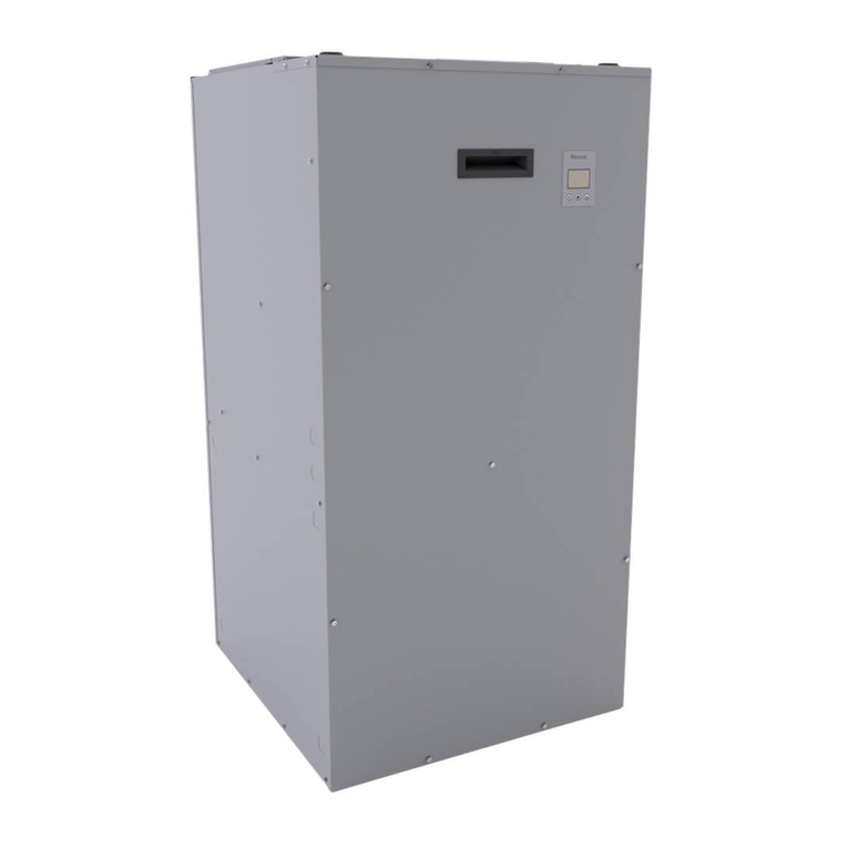
Rinnai AH083CP User manual

Hydronic Air Handler Installaon and Operaon Manual 1
•
•
•
•
•
•
•
•
•
•

2 Hydronic Air Handler Installaon and Operaon Manual

Hydronic Air Handler Installaon and Operaon Manual 3
• You must read the entire manual to
properly operate the air handler.
• It is recommended that a trained and
qualified professional who has attended a
Rinnai installation training class complete
your installation.
• Keep this manual for future reference.
Dealer Name:
Located on front of unit
Dealer Phone:
Purchase Date:
Serial #:
Thank you for purchasing Rinnai’s hydronic air
handler.
Before installing and operating the hydronic air
handler, be sure to read these instructions
completely and carefully to familiarize yourself
with the features and functionality.
This manual provides instructions for installing
the hydronic air handler and is a supplement
to the Rinnai Tankless Water Heater or Boiler
Installation and Operations Manual supplied
with the system.
The air handler must satisfy all the
requirements in the Tankless Water Heater or
Boiler Installation and Operations Manual, as
well as the requirements in this manual.
• It is recommended that a trained and
qualified professional who has attended
a Rinnai installation training class install
the air handler, inspect it, and leak test it
before use. Improper installation may
void the warranty.
• The trained and qualified professional
should have skills such as:
− Connecting water lines, valves,
electricity
− Knowledge of applicable national,
state, and local codes
− Installing ductwork and other
HVAC equipment
− Training in installation of air
handlers. Training on Rinnai’s
hydronic air handler is accessible
at www.rinnai-lms.com.
• Read all instructions in this manual
before installing the hydronic air
handler. The hydronic air handler must
be installed according to the exact
instructions in this manual.
• When installation is complete, leave this
manual with the air handler or give the
manual directly to the consumer.
• Proper installation is the responsibility of
the installer.

4 Hydronic Air Handler Installaon and Operaon Manual
Indicates an imminently hazardous
situation which, if not avoided, will result
in personal injury or death.
Indicates a potentially hazardous situation
which, if not avoided, could result in personal
injury or death.
Indicates a potentially hazardous situation
which, if not avoided, could result in minor
or moderate injury. It may also be used to
alert against unsafe practices.
DANGER
WARNING
This manual contains the following important
safety symbols. Always read and obey all safety
messages.
Safety alert symbol. Alerts you to
potential hazards that can kill or
hurt you and others.
CAUTION
The following precautions apply to the installer
and consumer. Read and follow all instructions in
this section.
• Before any work is undertaken, it is
imperative to observe all precautions as
stated in this manual.
• Wear safety glasses and work gloves.
Before installing or servicing the air handler,
turn off the power to unit. There may be more
than one disconnect switch. Electrical shock
can cause personal injury or death.
WARNING
• Suitable fire extinguishing equipment should
be immediately available in the work area
and be maintained in a state of readiness for
instant use.
• Do not use this air handler if any part has
been under water. Immediately call a
licensed professional to inspect the air
handler and replace any part that has been
under water.
• Do not use substitute materials. Use only
parts certified for the air handler.
• Do not use an extension cord or adapter plug
with this air handler.
• Any alteration to the air handler can be
dangerous and will void the warranty.
• This air handler must be installed indoors.
• Improper installation, modification, service,
maintenance or use of the air handler can
cause electrical shock, burns or other
conditions which may cause personal injury
or property damage.
• It is recommended that a trained and
qualified professional who has attended a
Rinnai installation training class complete
your installation.
• Read these installation instructions carefully
and adhere to all warning and caution
statements. Consult local building codes,
Occupational Safety and Health
Administration (OSHA), and National
Electrical Code (NEC) for special
requirements.

Hydronic Air Handler Installaon and Operaon Manual 5
The hydronic air handler is designed to work
with Rinnai tankless water heaters and boilers
(models listed below) to deliver a wide variety
of heating capacities for residential and light
commercial applications.
The hydronic air handler works with the following
Rinnai products:
• Rinnai Tankless Water Heaters:
− SENSEI™ SE+ Series
(RU Condensing Models)
− HE+ Series
(RL Non-Condensing Models)
− HE Series
(V Non-Condensing Models)
It is the responsibility of the installer to follow all
national codes, standards and local ordinances,
in addition to the instructions in this manual. The
installation must comply with regulations of the
local building, heating, plumbing, and other
codes. Where local codes are not applicable, the
installation must comply with the national codes
and all authorities having jurisdiction.
The following is a suggested list of codes and
standards for the United States and Canada:
General Installation
• Installation of Air Conditioning and
Ventilating Systems NFPA 91 (latest edition)
Duct Systems
• Sheet Metal and Air Conditioning
Contractors National Association (SMACNA)
• American Society of Heating, Refrigeration,
and Air Conditioning Engineers (ASHRAE)
• 2001 Fundamentals Handbook Chapter 34
or 2000 HVAC Systems and Equipment
Handbook Chapters 9 and 16
• US and CANADA: Air Conditioning
Contractors Association (ACCA) Manual D
Acoustical Lining and Fibrous Glass Duct
• US and CANADA: Current edition of
SMACNA; NFPA 90B as tested by UL
Standard 181 for Class I Rigid Air Ducts
Electrical Connections
• US: National Electrical Code (NEC) ANSI/
NFPA 70 (latest edition)
• CANADA: Canadian Electrical Code CSA
C22.1 (latest edition)
Plumbing Systems
• US and CANADA: ICC International
Plumbing Code (IPC); Uniform Mechanical
Code (UMC); Uniform Plumbing Code (UPC)
Refer to section “3.8 Specifications” for a
complete list of product specifications.
NOTE
NOTE
Tankless water heaters must have a
minimum input rate of 160,000 Btu/hr.
• Rinnai Boilers:
− I-Series (Condensing) Combi Models
If utilizing a boiler, ensure the output of
the boiler exceeds the capacity of the
air handler in use (the boiler Btu/hr
rating must be greater than the air
handler Btu/hr rating).
NOTE

6 Hydronic Air Handler Installaon and Operaon Manual
When transporting components of the hydronic
air handler, follow the guidelines below:
• Choose the correct hand truck to support
the weight and size of the system
components. Refer to section “3.8
Specifications” for specific weights and
dimensions.
• Use safe lifting and material handling
principles to prevent workplace accidents.
• Use proper lifting techniques to load the
equipment onto a hand truck.
• Position the equipment onto the hand
truck so the weight is evenly balanced.
• Use personal protective equipment, such
as gloves and steel-toed boots.
If storing components of the hydronic air
handler, follow the guidelines below:
• Store system components in a clean, dry
environment.
• Components must be protected from
direct sunlight.
• Do not store components outdoors.
• If transported or stored at temperatures
below 32°F (0°C), the components must
be warmed up to 60°F (15°C) before the
start of assembly.
• All components must be stored in the
original packaging.
Example:
AH083CP
AH 08 3CP
Blower Motor
P = 3-Speed
PSC Motor
Circulating Pump
C = Circulation Pump
Included
(Model numbers without a
“C” do not include an
internal circulation pump)
Nominal Heating Capacity
at 140° F
3 = 30,000 BTU
4 = 40,000 BTU
5 = 50,000 BTU
6 = 60,000 BTU
Size / Air Flow
08 = 800 CFM
12 = 1,200 CFM
16 = 1,600 CFM
20 = 2,000 CFM
Series
AH Series

Hydronic Air Handler Installaon and Operaon Manual 7
120V Power Supply
Knockout Access Port 1
24V Thermostat Cable
Knockout Access Port
(available on left or right
side)
Left or Right Side HVAC
Duct Return
Corrosion Resistant Cabinet
(made of heavy gauge
galvanized steel)
3-Speed PSC Blower
Motor and Housing
Control Panel
Water Inlet
Hot Water From Water Heater/
Boiler into Air Handler
Hydronic
Coil
Circulation Pump (for models
with integrated pump).
Circulates hot water between
the air handler and tankless
water heater/boiler.
Water Outlet
Cold Water Returning to
Water Heater/Boiler
Bottom HVAC
Duct Return
• Reference to the "top" and "bottom"
are referring to the location in this
image and will not change based on
orientation of the product.
• Cover is removed in above image to
show the air handler internal
components.
NOTE
TOP
BOTTOM
1 120V Power Supply Knockout Access Port:
• Located on right side panel for air handler
models AH083P/CP, AH084P/CP, AH125P/
CP, and AH166P/CP.
• Located on left side panel for air handler
models AH206P/CP.
A-Coil and Ductwork
(Field-Supplied)
Control Panel
Air Handler
Water Outlet to
Water Heater/Boiler
Water Inlet From
Water Heater/Boiler
Refrigerant Lines (Field-
Supplied) to Condensing Unit

8 Hydronic Air Handler Installaon and Operaon Manual
The ductwork in the above image is for representation purposes only; it is not a
complete system. Please follow standard duct design protocols for installation.
RETURN
(Air Flows In)
SUPPLY
(Air Flows Out)
Thermostat
Supply
Ductwork
Return
Ductwork
Air Handler
Rinnai Tankless
Water Heater
or Boiler
Front
Panel
A call for heat from the
thermostat activates the
air handler
IMPORTANT
Water Inlet
Water Outlet
Hot Water From
Water Heater/Boiler
into Air Handler
Cold Water From
Air Handler Returning
to Water Heater/Boiler
Example Vertical (Upflow with
Side Return) Configuration

Hydronic Air Handler Installaon and Operaon Manual 9
• Upflow
The blower should be set on top of the coil
section being used and the blower must be
supported on the bottom only and set on
solid floor or a field-supplied supporting
frame.
• Side Return (Left or Right Side)
Cut and remove panel as indicated by
perforations. Attach evaporator coil with
sheet metal screws (if using). Ensure bottom
portion of unit is sealed properly to prevent
air leakage.
• Bottom Return
The air handler must be supported on the
underside only and set on a field-supplied
supporting frame. Remove the bottom plate
of the air handler to create an air return
opening. Securely attach the air handler to
the supporting frame.
The air handler is approved for the following
configurations:
• Vertical: Upflow with bottom or side (left or
right side) return
• Horizontal: Upflow with bottom return
SUPPLY (Upflow)
RETURN
The air handler is not approved for the
following configurations:
• The air inlet is not allowed in the front
or back of the air handler.
Front
Back
• Multiple air handlers configured for
installation with a single Rinnai
tankless water heater or boiler is
prohibited.
• Do not position the air handler on its
front panel.
Front
Air flows in through bottom or
side (left or right side)
Vertical (upflow with bottom or side return)
Air flows out through top
Horizontal (Upflow with bottom return)
RETURN
Air flows in
through
“bottom
duct return”
SUPPLY
Air flows
out
through
“top”

10 Hydronic Air Handler Installaon and Operaon Manual
AH083CP AH084CP AH125CP AH166CP AH206CP
Appliance Type Hydronic Air Handler
(With Internal Circulation Pump)
Installation Indoor (approved for manufactured housing and mobile homes)
Suitable for Potable Water Systems Yes
Configurations • Vertical: Upflow with bottom or side (left or right side) return
• Horizontal: Upflow with bottom return
Circulation Pump Included Yes (Factory Installed)
Product Weight - lb. (kg) (approximate) 66 (30) 66 (30) 66 (30) 71 (32) 83 (38)
Cabinet Construction Embossed cabinet in heavy gauge galvanized steel to prevent
corrosion. Cabinet lined with 5/8 in. foil faced insulation.
Nominal CFM (Cubic Feet/Minute) 800 800 1,200 1,600 2,000
Nominal Output Btu/hr at 140°F130,000 40,000 50,000 60,000 60,000
Rated Voltage 120 V, 60 Hz, 1 Ph
Transformer Size and Type 40 VA, Class 2
Blower Wheel (Diameter x Width) 9x6 in. 9x6 in. 10x8 in. 10x8 in. 10x10 in.
Blower Motor Type 3-Speed PSC
Blower Motor Hot Water Coil Rows 343
Blower Motor Coil Material Copper Coil, UV Resistant Pan
Blower Motor Horsepower (HP) 1/3 1/3 1/2 3/4 3/4
Blower Full Load Amps (FLA) 5.3 5.3 7.1 7.5 10.5
Water Connection 3/4 in. Sweat
Pump Voltage 120 V
Pump Amps 1.4 Amps
Control Board
• Factory Installed
• Freeze protection activates at 40°F and deactivates at 70°F
• Thermostat connections
• 60-second time delay for blower activation
• Pump timer circulates water for one minute every six hours to
prevent stagnation of water in the system
• Boiler activation dry contact
• 24V AC isolation valve control
Certifications ETL Listed
Rinnai products are continually being updated and improved; therefore, specifications are subject to
change without prior notice.
1 Reference tables in sections 3.8.4 and 3.8.5 for specific BTU output.

Hydronic Air Handler Installaon and Operaon Manual 11
AH083P AH084P AH125P AH166P AH206P
Appliance Type Hydronic Air Handler
(Internal Circulation Pump Not Included)
Installation Indoor (approved for manufactured housing and mobile homes)
Suitable for Potable Water Systems Yes
Configurations • Vertical: Upflow with bottom or side (left or right side) return
• Horizontal: Upflow with bottom return
Circulation Pump Included No
Product Weight - lb. (kg) (approximate) 57 (26) 57 (26) 57 (26) 62 (28) 74 (34)
Cabinet Construction Embossed cabinet in heavy gauge galvanized steel to prevent
corrosion. Cabinet lined with 5/8 in. foil faced insulation.
Nominal CFM (Cubic Feet/Minute) 800 800 1200 1600 2000
Nominal Output Btu/hr at 140°F130,000 40,000 50,000 60,000 60,000
Rated Voltage 120 V, 60 Hz, 1 Ph
Transformer Size and Type 40 VA, Class 2
Blower Wheel (Diameter x Width) 9x6 in. 9x6 in. 10x8 in. 10x8 in. 10x10 in.
Blower Motor Type 3-Speed PSC
Blower Motor Hot Water Coil Rows 34 3
Coil Material Copper Coil, UV Resistant Pan
Blower Motor Horsepower (HP) 1/3 1/3 1/2 3/4 3/4
Blower Full Load Amps (FLA) 5.3 5.3 7.1 7.5 10.5
Water Connection 3/4 in. Sweat
Control Board
• Factory Installed
• Freeze protection activates at 40°F and deactivates at 70°F
• Thermostat connections
• 60-second time delay for blower activation
• Boiler activation dry contact
• 24V AC isolation valve control
Certifications ETL Listed
Rinnai products are continually being updated and improved; therefore, specifications are subject to
change without prior notice.
1 Reference tables in sections 3.8.4 and 3.8.5 for specific BTU output.

12 Hydronic Air Handler Installaon and Operaon Manual
2 Factory default setting for both heating and cooling.
Air Handler
Models Speed Air Flow (CFM) vs External Static Pressure (WC)
0.1 0.2 0.3 0.4 0.5
AH083P
AH083CP Low 749 705 658 614 558
Med2865 815 760 708 646
High 904 836 801 740 681
AH084P
AH084CP Low 749 705 658 614 558
Med2865 815 760 708 646
High 904 836 801 740 681
AH125P
AH125CP Low 1198 1144 1086 1018 962
Med21257 1198 1130 1072 1010
High 1273 1215 1158 1094 1018
AH166P
AH166CP Low 1576 1514 1433 1338 1264
Med 1643 1576 1490 1407 1320
High21707 1606 1545 1441 1364
AH206P
AH206CP Low 1759 1691 1652 1580 1512
Med 1838 1788 1729 1644 1555
High21928 1867 1810 1729 1637
3-Speed PSC Motor Speed Table
• Results are obtained while air handler is operating with a dry DX coil and air filter installed.
• Values are nominal and blower performance can vary higher or lower from these values based on the
evaporator coil that is used. Hot water heat air flow performance data includes associated air pressure
drop across a four-row hot water coil for models AH084P/CP, AH125P/CP, and AH166P/CP, and air
pressure drop across a three-row hot water coil for models AH083P/CP and AH206P/CP.
Domestic hot water recirculation circulates hot water through the plumbing system so that instant hot water is
available. Domestic hot water recirculation operates between calls for heat to ensure a balance of comfort for
HVAC heating and domestic hot water. If pairing a Rinnai Hydronic Air Handler with a tankless water heater for
domestic hot water recirculation capabilities, Rinnai recommends the following:
• Use an external recirculation pump controlled by a timer, aquastat, and/or an on-demand type control.
Do not use a Rinnai Tankless Water Heater equipped with recirculation capability1 with the Rinnai
Hydronic Air Handler.
• Size the air handler based off of the maximum allowable temperature for the domestic hot water system.
Refer to section “5.7.3 Domestic Hot Water Recirculation Piping Diagrams” for domestic hot water recirculation
piping diagrams.
For more information on domestic hot water recirculation, refer to the tankless water heater installation and
operation manual.
1 Rinnai Tankless Water Heaters equipped with recirculation capability include the SE+ Series featuring ThermaCirc360™
models (Super High-Efficiency Plus RUR Models).
This section is referring to domestic hot water recirculation in the plumbing system and not the circulation
of hot water between the air handler and tankless water heater/boiler.
IMPORTANT

Hydronic Air Handler Installaon and Operaon Manual 13
Air Handler
Model
Entering Water
Temperature
Blower Speed (Btu/hr)
Low Medium High
AH083CP
120°F 21,000 23,000 24,000
140°F* 29,000 31,000* 34,000
160°F 37,000 40,000 43,000
AH084CP
120°F 22,000 25,000 27,000
140°F* 31,000 35,000* 38,000
160°F 40,000 44,000 47,000
AH125CP
120°F 31,000 33,000 34,000
140°F* 43,000 45,000* 47,000
160°F 55,000 58,000 61,000
AH166CP
120°F 40,000 41,000 42,000
140°F* 55,000 57,000 58,000*
160°F 70,000 73,000 75,000
AH206CP
120°F 40,000 41,000 41,000
140°F* 55,000 56,000 57,000*
160°F 70,000 71,000 72,000
•
•
Air Handler
Model
Entering Water
Temperature
Blower Speed (Btu/hr)
Low Medium High
AH083CP
120°F 21,000 23,000 25,000
140°F* 29,000 32,000* 34,000
160°F 38,000 41,000 45,000
AH084CP
120°F 23,000 26,000 28,000
140°F* 32,000 35,000* 39,000
160°F 41,000 45,000 49,000
AH125CP
120°F 32,000 34,000 35,000
140°F* 44,000 46,000* 49,000
160°F 57,000 60,000 63,000
AH166CP
120°F 42,000 43,000 44,000
140°F* 57,000 59,000 61,000*
160°F 74,000 76,000 79,000
AH206CP
120°F 41,000 42,000 43,000
140°F* 56,000 57,000 58,000*
160°F 73,000 74,000 76,000
* Bold text is default setting.
NOTE
Tankless water
heaters must have a
minimum input rate
of 160,000 Btu/hr.
Values shown in following tables may vary depending on the static pressure of the duct system.
NOTE
Tankless water
heaters must have a
minimum input rate
of 160,000 Btu/hr.

14 Hydronic Air Handler Installaon and Operaon Manual
Air Handler
Model
Entering Water
Temperature
Blower Speed (Btu/hr)
Low Medium High
AH083P
120°F 21,000 23,000 25,000
140°F* 29,000 32,000* 35,000
160°F 38,000 42,000 45,000
AH084P
120°F 23,000 25,000 27,000
140°F* 32,000 35,000* 38,000
160°F 41,000 46,000 50,000
AH125P
120°F 32,000 33,000 35,000
140°F* 44,000 47,000* 49,000
160°F 57,000 60,000 63,000
AH166P
120°F 41,000 42,000 44,000
140°F* 58,000 60,000 62,000*
160°F 75,000 78,000 80,000
AH206P
120°F 41,000 42,000 43,000
140°F* 58,000 60,000 61,000*
160°F 75,000 77,000 78,000
Air Handler
Model
Entering Water
Temperature
Blower Speed (Btu/hr)
Low Medium High
AH083P
120°F 21,000 23,000 25,000
140°F* 29,000 32,000* 35,000
160°F 38,000 41,000 45,000
AH084P
120°F 23,000 25,000 27,000
140°F* 32,000 35,000* 39,000
160°F 41,000 46,000 50,000
AH125P
120°F 32,000 34,000 35,000
140°F* 45,000 47,000* 50,000
160°F 58,000 61,000 64,000
AH166P
120°F 41,000 43,000 44,000
140°F* 58,000 60,000 62,000*
160°F 75,000 78,000 80,000
AH206P
120°F 41,000 42,000 43,000
140°F* 58,000 60,000 61,000*
160°F 76,000 77,000 79,000
•
IMPORTANT
• All capacities are based on 70°F entering air temperature.
• For entering air temperatures other than 70°F, use the following capacity correction factors:
(72°F x .982), (68°F x 1.02), (66°F x 1.04)
• Glycol correction factors: (10% X .98), (20% X .95), (30% X .92), (40% X .88)
• Refer to the “Approved Cleaners, Inhibitors and Antifreezes” section (in the Appendix of the “I-Series
Condensing Combi Boiler Installation and Operation Manual”) for a complete list of approved glycols.
* Bold text
is default
setting
•
* Bold text
is default
setting

Hydronic Air Handler Installaon and Operaon Manual 15
Measurements: in. (mm)
D
E
Hydronic Air Handler Models
• AH083CP
• AH083P
• AH084CP
• AH084P
• AH125CP
• AH125P
• AH166CP
• AH166P
• AH206CP
• AH206P
A17.5 (445) 21.0 (533) 24.5 (622)
B27.0 (686) 28.0 (711) 28.0 (711)
C20.5 (521) 20.5 (521) 20.5 (521)
D15.5 (394) 19.0 (483) 22.5 (572)
E16.0 (406) 16.0 (406) 16.0 (406)
F25.4 (645) 26.4 (671) 26.4 (671)
G21.5 (546) 22.5 (572) 22.5 (572)
H21.4 (544) 22.4 (569) 21.4 (543)
I17.5 (445) 17.5 (445)16.5 (419)
H
A
I
G
FB
Water In
Water Out
Line Voltage1
(120V Supply)
Low Voltage/Thermostat
(24V Supply)2
RIGHT SIDE
2.8
(71)
16
(406)
1.6
(41)
16
(406)
FRONT
TOP
C
NOTE
• CP = Models with Internal
Circulation Pump
• P = Models without Internal
Circulation Pump
1 Line Voltage knockout is located at the specified height on the cabinet right side panel for models: AH083P/CP,
AH084P/CP, AH125P/CP, AH166P/CP
Line Voltage knockout is located at the specified height on the cabinet left side panel for models: AH206P/CP
2 Low Voltage/Thermostat knockouts are also available at same location on cabinet left side.

16 Hydronic Air Handler Installaon and Operaon Manual
Universal Air Handler Rack Assembly Part #
Universal rack assembly that mounts to the Rinnai Tankless Water
Heater or Boiler for simple installation with the hydronic air handler.
Works with all Rinnai AH Series Hydronic Air Handler models.
Includes hardware for mounting the tankless water heater or boiler to
the air handler rack assembly, and hardware for assembling the rack.
AHRACK-1
Domestic Priority Switch Part #
Normally Closed (NC) switch that connects to the PC Board in the
Rinnai tankless water heater or boiler.
Allows the tankless water heater or boiler to give priority to domestic
hot water by shutting off the air handler when necessary. When used
with a hydronic air handler, the switch gives priority to domestic hot
water. When domestic hot water demand exceeds a certain point, the
air handler will turn off to ensure the demand is met.
REU-OPU3
Pipe Cover Enclosure Part #
Encloses the piping below the tankless water heater or boiler for aesthetic purposes.
• Pipe cover for HE+ Series (RL Non-Condensing) Tankless Water
Heater Models PCD03-SM2
• Pipe cover for SENSEI™ SE+ Series (RU Condensing) Tankless
Water Heater Models and I-Series (Condensing) Combi Boiler
Models
PCD07-SM
• Pipe cover for HE Series (V Non-Condensing) Tankless Water
Heater Models PCD03-EWV
Product images are for illustrative purposes only.
24V NC Brass Solenoid Valve (3/4” NPT ) Part #
Optional accessory for use in domestic hot water recirculation
applications. The solenoid valve installs in line with the air handler
pump and is wired to the 24V Valve terminal on the air handler control
board. 1.12A Max Current Draw.
607000018
Heat Pump (HP) Lockout Kit Part #
This relay prevents unnecessary cycles on the air handler when
coupled with an electric heat pump.
605000032

Hydronic Air Handler Installaon and Operaon Manual 17
❽
❿
❹❾
❷
❻
❸
⓬
❼
❺
❶
⓫
Models With
Internal
Circulation Pump
Models Without
Internal
Circulation Pump
AH083CP
AH084CP
AH125CP
AH166CP
AH206CP
AH083P
AH084P
AH125P
AH166P
AH206P
#Description Rinnai Part # Quantity
1Pump - With Internal Check Valve, 120 Volts 607000033 1111100000
2Transformer - 120 Volt, 60 Hz. 605000044 1111111111
3Multi-Function Control Board 605000033 1111111111
4
7.5 MFD Capacitor 605000034 1100011000
10 MFD Capacitor 605000035 0010000100
12.5 MFD Capacitor 605000036 0001100011
56 Pin Wire Harness 605000037 1111111111
6Rinnai Wiring Harness 605000038 1111111111
7Door Switch 605000039 1111111111
8
Blower Motor 1/3 HP, 120 Volt, 60 Hz. 605000040 1100011000
Blower Motor 1/2 HP, 120 Volt, 60 Hz. 605000041 0010000100
Blower Motor 3/4 HP, 120 Volt, 60 Hz. 605000042 0001000010
Blower Motor 3/4 HP, 120 Volt, 60 Hz. 605000043 0000100001
9
9" x 6" Blower Housing Assembly 608000029 1100011000
10" x 8" Blower Housing Assembly 608000030 0011000110
10" x 10" Blower Housing Assembly 608000031 0000100001
10 Motor Mount Assembly (includes ring and legs) 609000063 1111111111
11
Hot Water Replacement Coil With Pump and
Valve Assembly 607000022 1000000000
607000023 0110000000
607000025 0001000000
607000026 0000100000
Hot Water Replacement Coil With No Pump and
Valve Assembly 607000027 0000010000
607000028 0000001100
607000030 0000000010
607000031 0000000001
12 3/4" Sweat Flange Kit 607000032 1111100000

18 Hydronic Air Handler Installaon and Operaon Manual
Gather the required tools and parts before
starting installation. Read and follow the
instructions provided with any tools listed below.
• 1/4 in. nut driver
• Level
• Screwdriver
• Adjustable wrench
• Tape Measure
• Hammer
• AHRI Approved Duct Sealant
• UL listed wire nuts
When choosing an installation location, you must
ensure proper clearances will be met; the
installation environment; water quality; and the
need for freeze protection.
Carefully unpack the air handler. If the unit is
damaged, contact your local dealer/distributor.
Do not attempt to use the air handler if it
appears damaged.
The blower section is factory assembled and all
components are performance tested.
The air handler consists of a blower assembly
and controls in an insulated, galvanized steel
factory finished enclosure. Knockouts are
provided for electrical wiring entrance.
Inspect the following:
• Check the air handler rating plate to confirm
specifications are as ordered.
• Upon receipt of air handler, thoroughly
inspect the system for possible shipping
damage. If the carton appears damaged,
closely examine the air handler inside the
carton.
• If the air handler appears to be damaged or
is torn loose from its anchorage, the air
handler must be immediately examined by
the receiving party before removal. If
damage is found, the receiving party must
sign the driver’s delivery receipt noting all
damage (i.e. carton damage and/or product
damage), as well as contact the last carrier
immediately, preferably in writing,
requesting inspection by the carrier’s agent.
• To prevent loss or damage, leave all parts
in original packages until installation.
Contaminant Maximum Level
Total Hardness Up to 200 mg/L
Aluminum * Up to 0.2 mg/L
Chlorides * Up to 250 mg/L
Copper * Up to 1.0 mg/L
Dissolved Carbon
Dioxide (CO2) Up to 15.0 mg/L
Iron * Up to 0.3 mg/L
Manganese * Up to 0.05 mg/L
pH * 6.5 to 8.5
TDS (Total Dissolved
Solids) * Up to 500 mg/L
Zinc * Up to 5 mg/L
* Source: Part 143 National Secondary
Drinking Water Regulations
This section provides information on the
importance of water quality to the air handler. The
information is intended to serve as general
guidelines only and is not a complete list of water
quality guidelines.
Consideration of care for the air handler should
include evaluation of water quality.
• The water must be potable, free of corrosive
chemicals, sand, dirt, or other contaminants.
• It is up to the installer to ensure the water
does not contain corrosive chemicals or
elements that can affect or damage the boiler
or tankless water heater.
• Water that contains chemicals exceeding the
levels below can damage the boiler or
tankless water heater.

Hydronic Air Handler Installaon and Operaon Manual 19
Replacement of components due to water
quality damage is not covered by the warranty.
• Unsuitable heating system water can cause
the formation of scale or sludge, which
affects system efficiency. It can also cause
corrosion and reduce life of the heat
exchanger.
• Never use water that has been treated by a
reverse osmosis, deionized, or distilled
water to soften the water to fill the heating
system.
• Louvers or return air grilles are field-supplied.
Local codes may limit application of systems
without a ducted return to single-story
buildings.
• For a unit installed in a closet with a louvered
return opening, the minimum open area for
the louvers are:
Non-Ducted Return Closet Installation
• Clearances to combustible material is 0 in.
from unit casing, and 0 in. to plenum and
duct for first 36 in. (914 mm) and throughout
the remaining ductwork system.
• Clearance for servicing is 24 in. (610 mm) in
front of air handler.
FRONT
0 in.
SIDE
0 in.
BACK
0 in.
TOP
0 in.
BOTTOM
0 in.
SERVICING
24 in.
(610 mm)
Images are not to scale and are for illustration purposes
only. Images do not show a complete system with
plenums, duct pipes, etc.
Clearances to
combustible
material is 0 in. to
plenum and duct for
first 36 in. (914 mm)
and throughout the
remaining ductwork
system.
IMPORTANT
• If the free area is not known, assume a 25%
free area for wood or a 75% free area for metal
louvers or grilles. Using the louver dimensions
and the 25% or 75% assumption, determine if
the louver open area meets the minimum open
area listed above.
• If the return air plenum is used, the return air
grille should be immediately in front of the
opening in the plenum to allow for the free flow
of return air.
• When not installed in front of the opening, there
must be adequate clearance around the air
handler to allow for the free flow of return air.
Air Handler Models Minimum Opening Area
• AH083P/AH083CP
• AH084P/AH084CP
320 square inches
(0.206 square meters)
• AH125P/AH125CP 360 square inches
(0.23 square meters)
• AH166P/AH166CP
• AH206P/AH206CP
450 square inches
(0.29 square meters)

20 Hydronic Air Handler Installaon and Operaon Manual
• This air handler is certified for installation in
residential and light commercial applications
and approved for the following configurations:
− Vertical: Upflow with bottom or side (left or
right side) return
− Horizontal (upflow with bottom return)
• All models are designed for indoor installation
only.
• These instructions are intended as a general
guide only and do not supersede national or
local codes. Compliance with all local, state, or
national codes pertaining to this type of
equipment should be determined prior to
installation.
• Read this entire manual, as well as the
instructions supplied in separate equipment,
before starting installation.
• It is recommended that a trained and qualified
professional who has attended a Rinnai
installation training class complete your
installation.
• Installation of the blower section, field wiring,
warm air ducts, etc. must conform to the
requirements of the National Electrical Code,
ANSI/NFPA No. 70 (latest edition) in the United
States, and any state laws, and local
ordinances (including plumbing or wastewater
codes). Local authorities having jurisdiction
should be consulted before installation begins.
Such applicable regulations or requirements
take precedence over the general instructions
in this manual.
• Install the conditioned air plenum, ducts and air
filters (not provided) in accordance with NFPA
90B Standard for the Installation of Warm Air
Heating and Air-Conditioning Systems (latest
edition). The blower section is provided with
flanges for the connection of the plenum and
ducts. Air filters must be listed as Class 2
furnace air filters. The blower section is shipped
from the factory completely assembled.
• For ease in installation, it is best to make any
necessary coil configuration changes before
connecting the air handler to the coil.
• Do not remove the cabinet knockouts until it
has been determined which knockouts need to
be removed for the installation.
• Select the final installation position that best
suits the site conditions. Consider required
clearances, space, and routing requirements for
refrigerant line, condensate disposal, filters,
ductwork, wiring, and accessibility for service.
Refer to the rating plate on the blower section
for specific information.
• When the unit is installed in a humid space
and used in cooling applications, excessive
sweating may occur on outside of unit. To
prevent excessive sweating wrap unit with
1 in. (25 mm) fiberglass insulation. All
openings should be sealed to prevent air
leakage that could cause condensate to
form inside the cabinet.
• If installed in an unconditioned space,
sealant should be applied around the
electrical wires, refrigerant tubing, and
condensate lines where they enter the
cabinet.
• Electrical wires should be sealed on the
inside where they exit the conduit opening.
Sealant is required to prevent air leakage
and condensate from forming inside the
blower, control box, and on the electrical
controls.
• The air handler and its complementing
cooling coil must be installed in such a way
as to allow free access to the air handler/
control compartment.
• The air handler and its complementing
cooling coil must be installed with a 3/4 in.
(19 mm) drop in the horizontal position
towards the drain pan to ensure proper
condensate drainage. The air handler and
coil should also be tilted 1/2 in. (13 mm)
from back to front toward the drain line.
The Clean Air Act of 1990 bans the
intentional venting of refrigerant (CFC’s and
HFC’s) as of July 1, 1992. Approved
methods of reclaiming must be followed.
Fines and/or incarceration may be levied for
non-compliance.
IMPORTANT
• Do not install this air handler if it is
damaged.
• Do not install this air handler if any part
or all of the unit has been under water.
Explosion Hazard:
• Keep flammable materials and vapors,
such as gasoline, away from this unit.
• Failure to follow these instructions can
result in death, explosion or fire.
WARNING
This manual suits for next models
9
Table of contents
Other Rinnai Air Handler manuals
Popular Air Handler manuals by other brands

Trane
Trane 2/4TGB3F42A Installer's guide

Zehnder Rittling
Zehnder Rittling ComfoSpot 50 manual

VES
VES ecovent NRG Installation, operation and maintenance manual

EQK
EQK 14S-EHVH18W2V troubleshooting manual

ActronAir
ActronAir ECOFLEX MINI VRF R-32 Series owner's manual

bora
bora USDFUM-001 Assembly instructions

Goodman
Goodman AWST Series manual

System air
System air Topvex SX/C Series installation instructions

Carrier
Carrier WeatherMaker 50TC 17-30 Series Service and maintenance instructions

DSSA
DSSA POWERMATE 15 Gen3 manual

COOK
COOK HMD Installation, operation and maintenance manual

Salda
Salda Smarty 3X P User and Service Technical Manual