manuals.online logo
Brands
  1. Home
  2. •
  3. Brands
  4. •
  5. Rinnai
  6. •
  7. Burner
  8. •
  9. Rinnai Linear 1500 User manual

Rinnai Linear 1500 User manual

Popular Burner manuals by other brands

Riello RLS 160/EV Installation, use and maintenance instructions

Riello

Riello RLS 160/EV Installation, use and maintenance instructions

Riello RS 28/M Installation, use and maintenance instructions

Riello

Riello RS 28/M Installation, use and maintenance instructions

True Induction TI4B user guide

True Induction

True Induction TI4B user guide

Riello RG1RKD Installation, use and maintenance instructions

Riello

Riello RG1RKD Installation, use and maintenance instructions

Weishaupt WG20 Series manual

Weishaupt

Weishaupt WG20 Series manual

Carolina Cooker M116672 owner's guide

Carolina Cooker

Carolina Cooker M116672 owner's guide

Riello RX 500 S/PV Modulating operation

Riello

Riello RX 500 S/PV Modulating operation

Unigas HTP2000 installation manual

Unigas

Unigas HTP2000 installation manual

baltur BT 250 DSG 4T manual

baltur

baltur BT 250 DSG 4T manual

muenkel design round burner Operating and installation instructions

muenkel design

muenkel design round burner Operating and installation instructions

baltur BT 14 DSGW Instruction

baltur

baltur BT 14 DSGW Instruction

artisan Art-SB1 Care & use manual

artisan

artisan Art-SB1 Care & use manual

AESYS TurboFire II Installation, operation and maintenance manual

AESYS

AESYS TurboFire II Installation, operation and maintenance manual

IKEA GRILLSKÄR manual

IKEA

IKEA GRILLSKÄR manual

baltur TBL 1000 ME Instruction manual for installation, use and maintenance

baltur

baltur TBL 1000 ME Instruction manual for installation, use and maintenance

Riello Burners P 200 P/G Installation, use and maintenance instructions

Riello Burners

Riello Burners P 200 P/G Installation, use and maintenance instructions

WLD-TEC powerjet instruction manual

WLD-TEC

WLD-TEC powerjet instruction manual

Riello RDB 3.2 BX 32/50 Installation, use and maintenance instructions

Riello

Riello RDB 3.2 BX 32/50 Installation, use and maintenance instructions

manuals.online logo
manuals.online logoBrands
  • About & Mission
  • Contact us
  • Privacy Policy
  • Terms and Conditions

Copyright 2025 Manuals.Online. All Rights Reserved.

Linear 1500 burn media installation: 13570-C | 1
Experience has shown that the majority of performance problems are caused by burn media being
installed incorrectly. Please take the time to read and follow these instructions as malfunctioning
due to incorrect burn media placement is not covered by warranty.
• The Linear MUST NEVER be used with other burn media or burn media that is damaged.
• The Linear burn media sets are di󰀨erent and cannot be interchanged, ensure you have ordered
the correct set before installation.
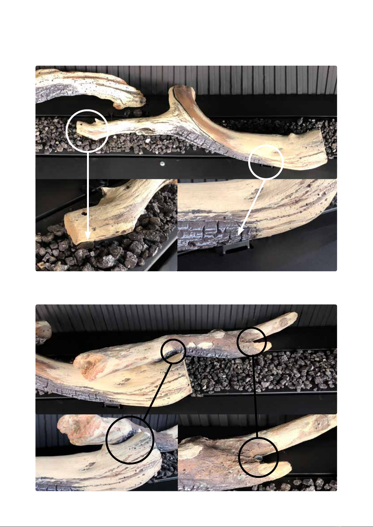
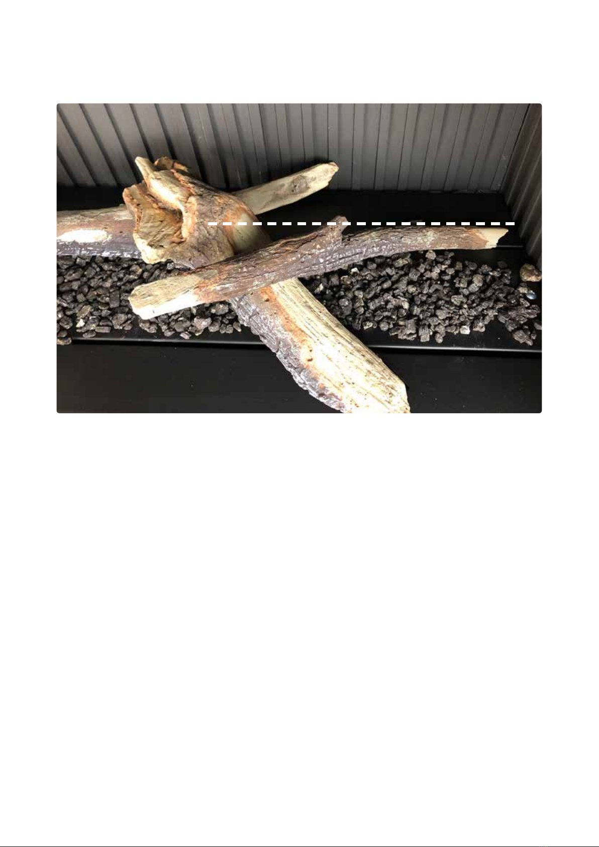
Correct placement
It is important to place the burn media in the correct position. Incorrect placement can create
carbon build-up and a󰀨ect performance.
Single-sided/double-sided
When installing the burn media you will ALWAYS be working on the side where the pilot assembly
is to the back of the rebox.
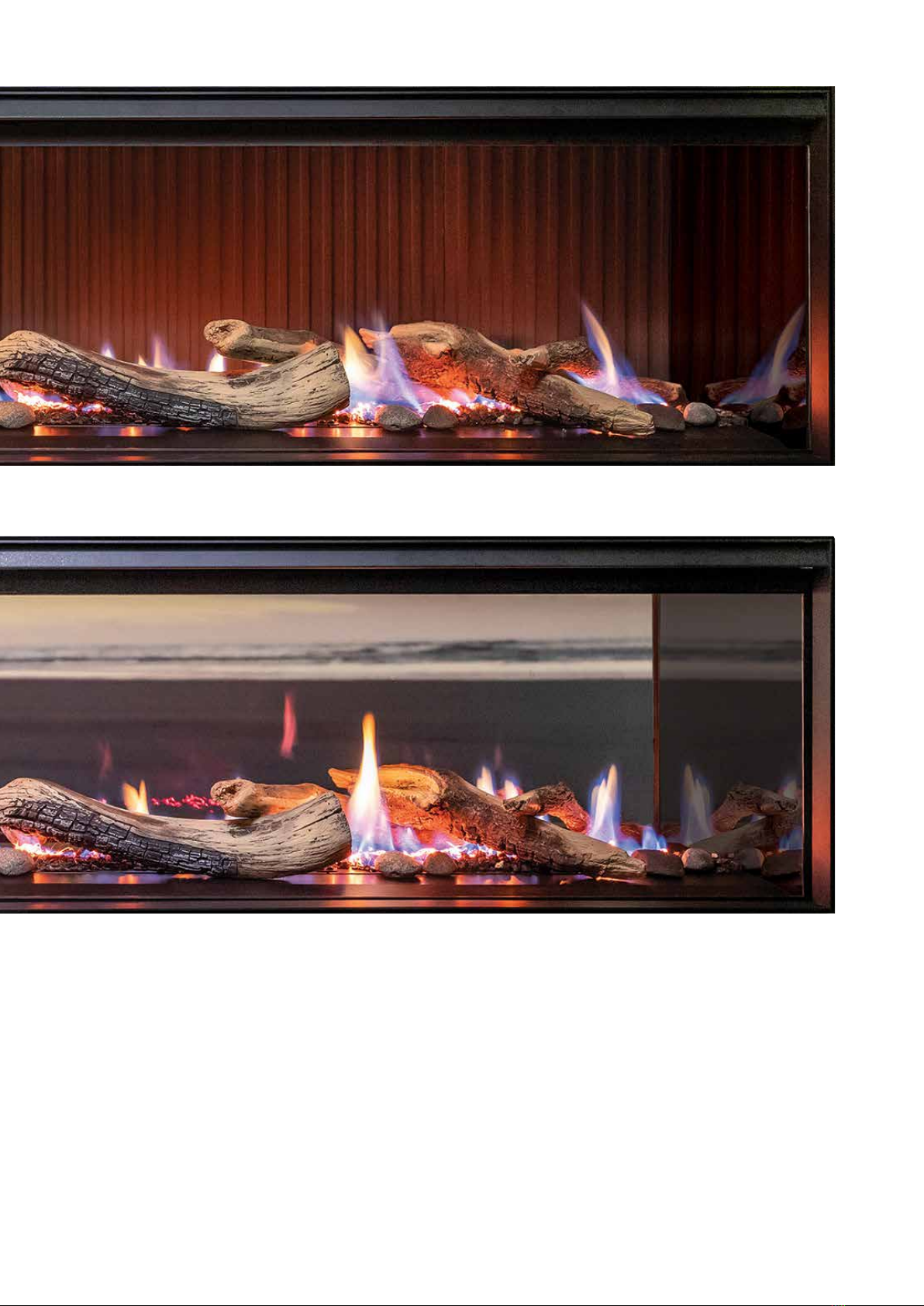
R2903 Linear 1500 driftwood log set kit contents
Part number Description Quantity
13044 Vermiculite 1 bag (approx. 0.75 L)
13476 Wire wool (glowing ash) 1 bag (approx. 3 g)
13480 Log set A and stone set14 logs and 9 stones
13481 Log set B 3 logs
1Log set A and stone set come packaged in the same box
R2905 Linear 1500 modern media kit contents
Part number Description Quantity
13473 Crushed black glass 3 bags (approx. 3.5 kg)
13476 Wire wool (glowing ash) 1 bag (approx. 3 g)
Linear 1500
Burn media installation
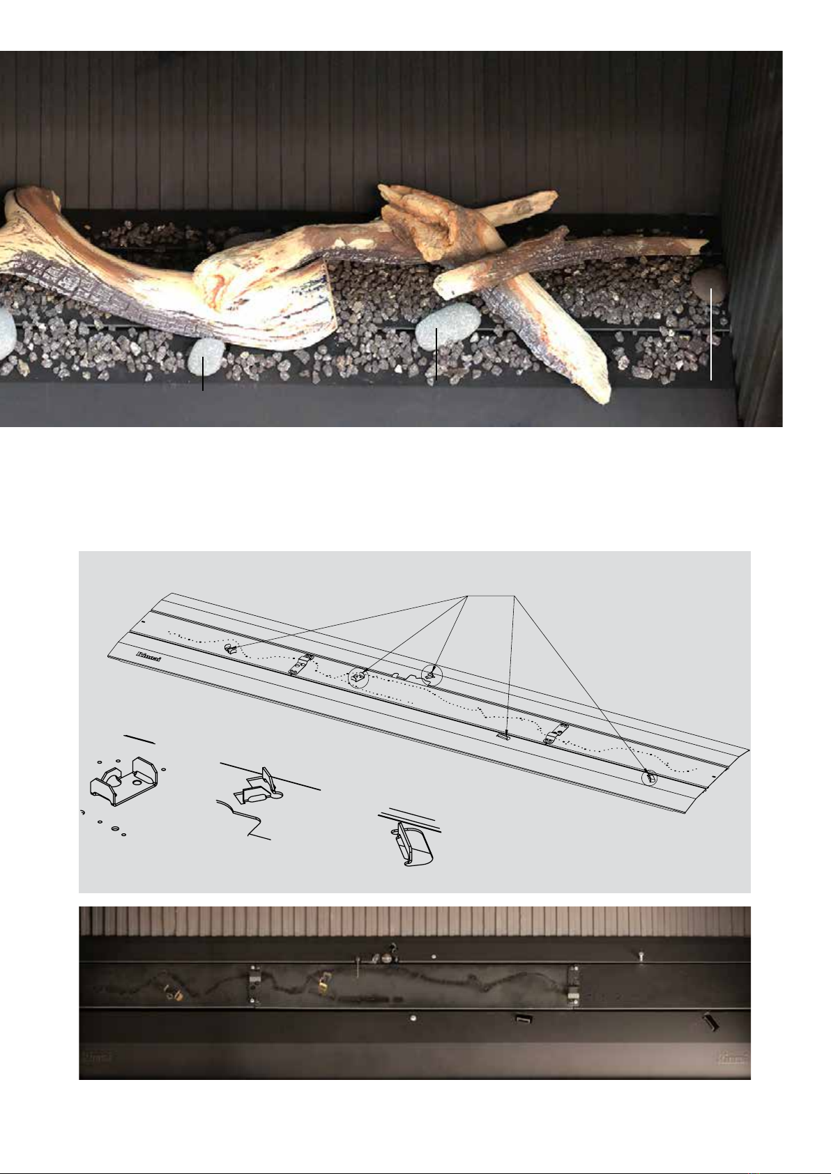
Ensure the gaps between the burners are kept clear of any vermiculite or crushed glass. This is
important as these gaps provide secondary air to the unit.
A tip to stop any burn media going into the gaps is to place the installation guide in the burner
gap while placing the vermiculite or crushed glass over the burner.
Important
2| Linear 1500 burn media installation: 13570-C
We recommend identifying the log sections before installation—lay them on the oor in a
conguration resembling the above. This will ensure you’re not forcing incorrect log pieces onto the
burner supports and scratching the paint.
1 7 8 12 13
Linear log set BLinear log set A
(includes log set AND
stone set)
A1
A2 A3 A4
B1 B2 B3
2 5 9 13
Stone set (numbers are stamped on the back)
Grey stones
Vermiculite
Wire wool
Brown stones
Driftwood log set (charred side face down)
Grey 7
A3
B3
A2 Brown 5
Brown 13
Grey 8
Brown 9
Linear 1500 burn media installation: 13570-C | 3
1. Fold up the laser cut burner surrounds and tabs
The burners have laser cut sections and tabs that need to be folded up (refer images below) to
position the logs.
A
B
C
Log locators
Detail A
scale 1:1
Detail B
scale 1:1
Detail C
scale 1:1
Grey 1
A1
Grey 12 B2
B1
A4
Grey 13 Brown 2
4| Linear 1500 burn media installation: 13570-C
2. Spread vermiculite
Using the image on p. 2 for reference, spread (DO NOT POUR) approximately three quarters of
the bag of vermiculite across the burners in a single layer. Start the re and check for complete
burner ignition.
Important:
• Avoid blocking the pilot and ame rod ports
• Ensure clearance around the left and right hand log locators
• Ensure the gaps between the burners are kept clear
Clear area around pilot and ame
rods
B3
3. Add the wire wool
Remove small sections of the wire wool (refer images on p. 10-11) and place where the ames
will be. These provide a glow e󰀨ect and will enhance the ame picture. Keep away from the pilot
assembly as this can cause the ame rods to earth out.
4. Install B3 from log set B (for all log pieces—charred side faces down)
Position B3 from log set B. The LH sections sits ON the log locator, RH section sits up against the
metal log tab.
Clear area around the log
locators
LH sits ON the log locator RH up against the metal log tab
Linear 1500 burn media installation: 13570-C | 5
5. Install A1 (from log set A)
Position A1, the LH section ts snugly into the two corner metal log locators, the RH section ts
inside AGAINST the log locator.
B3
A1
6. Install B2 (from log set B)
Position B2, the LH section rests in the cradle of A1, RH section, where the log splits, sits around
the log locator pin.
A1
B2
6| Linear 1500 burn media installation: 13570-C
7. Install B1 (from log set B)
Position B1, the LH section rests in the curve of B2. The log locator for the RH section sits behind
the log—push the back of the log against the locator.
8. Install A2 and A3 (from log set A)
A3 sits towards the back end of the burner. The RH section rests on B3. DO NOT cover the larger
burner holes. Log A2 sits on B3—keep clear of the larger burner hole. Note the angle position in
relation to B3.
B1
B2
Log locator
positioned here
A3
B3
A2
A3
Linear 1500 burn media installation: 13570-C | 7
9. Install A4 (from log set A)
A4 sits B1, ensure the large burner holes are not covered.
10. Install the stone set
Using the assembled image on p.2-3, position the stones. Unlike the log pieces the stones can be
positioned where you like, however DO NOT place over the burner ports. Stones 1, 5, or 7 can be
placed in the cross-lighting bridges.
11. Position the left over vermiculite
Place the remaining vermiculite around the burners and use to cover the metal log locator
brackets, if they are showing, and any other gaps.
12. Test operation
Check for cross-lighting and complete ame across all the burners, and check impingement on the
logs. Adjust logs A2, A3, or A4 if required. Some ames may lean back in the re until the glass has
been installed. Refer following page for nal ame pattern (with glass on) for the single and double-
sided models.
A4
B1
B2
8| Linear 1500 burn media installation: 13570-C
Final ame pattern 1500 log set (single-sided)
Final ame pattern 1500 log set (double-sided)
Linear 1500 burn media installation: 13570-C | 9
Final ame pattern 1500 log set (single-sided)
Final ame pattern 1500 log set (double-sided)
10 | Linear 1500 burn media installation: 13570-C
Crushed glass and wire wool
1. Evenly spread the complete bag of crushed glass over the surface of the burner BETWEEN
the fold lines of the back and front burner. Ensure the gaps between the burners are kept
clear of glass pieces. This is important as these gaps provide secondary air to the unit, refer
guide on how to keep clear on the front page.
2. Remove SMALL sections of the wire wool and place evenly across the burner where the ames
will be (otherwise it will do nothing). These provide a glow e󰀨ect and will enhance the ame
picture.
Important: Make sure the area around the pilot assembly is kept clear.
3. Test operation by checking for cross-lighting and complete ame across all the burners. Some
ames may lean back in the re until the glass has been installed.