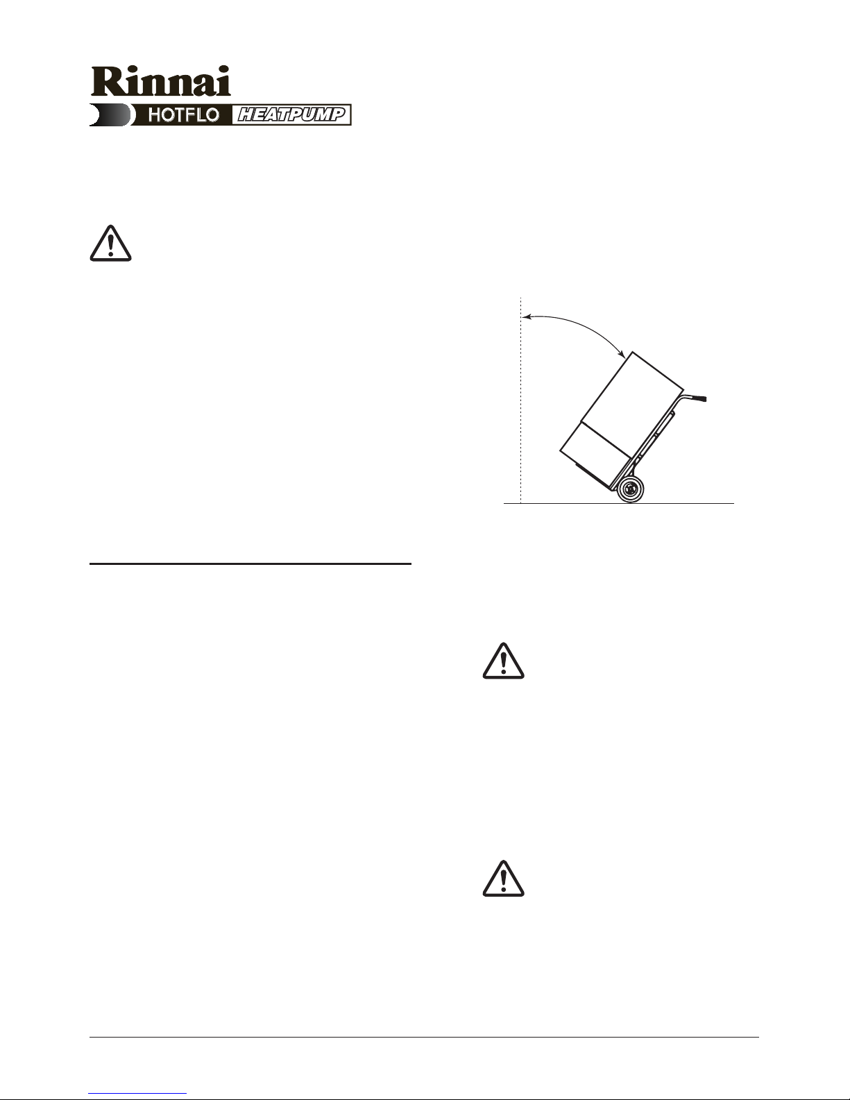
Rinnai RIN250EHP Installation instructions

Installation and Owner’s Manual
Model: RIN250EHP
H4123 025961 Rev. A July 2012
Electric Heat Pump
Specications and materials may change without notice.
Effective for Heat Pump water heaters manufactured and sold after 1st May 2011.
Carefully remove all packaging and
transit protection from the heater before
installation. Dispose of the packaging
responsibly using re-cycling facilities
where they exist.
Installation Details
Owner’s Information
Warranty
For advice, repairs and service, call:
1300 555 545

H4123 025961 Rev. A July 2012
Installation and Owner’s Manual – Heat Pump
Rough-In Diagram 2
Installation Instructions 3
Installation Declaration 12
Owner’s Manual 13
Troubleshooting 19
System Maintenance 21
Safety Information 22
Warranty 23
Contents

1
H4123 025961 Rev. A July 2012
Installation and Owner’s Manual – Heat Pump
About the Rinnai Heat Pump
The Rinnai Heat pump is a very efcient
water heater that can signicantly
reduce energy consumption as
compared to an electric storage system.
The principle of its operation is very
similar to the operation of a refrigerator,
but in reverse. There is latent heat
energy in the air and this is transferred
to the heating system and the water.
The warmer the climate in which it is
installed, the more efcient the heat
pump system will be at heating water.
Heat Pump Installation
While heat pumps work best in warmer
climates, they will continue to work in
cooler areas.
The map below shows the cooler areas
of Australia shaded in gray.
In these cooler areas, consumers may
experience longer hot water heat-up
times in winter. Because the efciency
benets of heat pumps in these
conditions is reduced compared to
other hot water systems, installation
of heat pumps in these areas is not
recommended.
Perth
Melbourne
Heat pumps not recommended in these areas
Hobart
Darwin
Brisbane
Sydney
Adelaide
Based on average winter temperature figures from the Bureau of Meteorology
For further information, see http://www.bom.gov.au
Canberra

2H4123 025961 Rev. A July 2012
Installation and Owner’s Manual – Heat Pump
Rough-In Diagram
100
632
1711
1211
508
195
Hot
Cold
Tempering
Valve
700
150
150
Allow 700 mm clearance
above and 150mm
clearance to either side
of the unit
Allow 50% of the height of the
water heater for clearance
above to replace the anodes
Net weight = 107kg
Model E2FHG4HWOC shown

3
H4123 025961 Rev. A July 2012
Installation and Owner’s Manual – Heat Pump
Regulatory Requirements
This water heater must be installed
by a licensed tradesperson, and in
accordance with:
• AS/NZS3500.4.2 “National
Plumbing and Drainage Code Hot
Water Supply Systems – Acceptable
Solutions”.
• AS/NZS3000.
• Local authority regulations.
• Outside Australia and New Zealand,
please refer to local plumbing and
building codes and regulations.
• Notice to Victorian customers from
the Victorian Plumbing Industry
Commission – this water heater must
be installed by a licensed person as
required by the Victorian Building Act
(1993). Only a licensed person will give
you a compliance certicate, showing
that the work complies with all the
relevant Standards and only a licensed
person will have insurance protecting
their workmanship for 6 years.
Note: This water heater and
heat pump components are
not suitable for pool heating.
Specications
The net weight of the heat pump is
107kg.
Dimensions are shown in the rough in
diagram in this manual.
Installation Instructions

4H4123 025961 Rev. A July 2012
Installation and Owner’s Manual – Heat Pump
Transport and Handling
Critical: When moving the unit,
it must be close to vertical at
all times.
When using a trolley to move
the unit, ensure it is not
tilted more than 45° from the
vertical.
Non-compliance will void
warranty and severely affect
product performance and
operation.
Step 1
• Arrive at site and conduct a safety
audit.
• Safety audits can also be known as
Work Method Statements (WMS) or
Job Site Analysis (JSA).
• Park your vehicle as close as
allowable to your installation.
• Unload all materials in a safe manner.
• Position all materials in a convenient
position near the work area.
• The existing tank (if applicable)
should be drained and removed in a
responsible manner.
Never tilt unit more than
45˚ from vertical
Installation Instructions
Note: Do not commence
a job where the risks
cannot be controlled.
Note: Do not drain on to
grass or garden beds.

5
H4123 025961 Rev. A July 2012
Installation and Owner’s Manual – Heat Pump
Placement of New Tank
Step 2
• The water heater must be installed
outdoors, close to the most
frequently used hot water outlet.
• Optimum installation location is on
the warmest side of house.
• The location must consider noise
impact on living areas. Avoid
positioning near bedrooms or
neighbours’ bedrooms. Although the
running noise level is very low (51
dB(A)) it can be expected that the
heat pump will run during the night.
• Adequate access must be available
to the relief valve and anodes.
• Safely position the new unit on a
level surface in accordance with all
plumbing and building regulations.
• A properly drained overow tray
must be used where property
damage could occur from water
spillage. (See AS/NZS3500.4.2 for
further details.)
Note: The warranty does not
cover consequential damage
due to leakage of the water
heater.
Installation Instructions
Heat Pump
P
r
e
f
e
r
r
e
d
i
n
s
t
a
l
l
a
t
i
o
n
p
o
s
i
t
i
o
n
Install a plinth under the
water heater where the
water heater is subjected
to wet conditions

6H4123 025961 Rev. A July 2012
Installation and Owner’s Manual – Heat Pump
• Allow 200m3 of free space
surrounding the unit. This provides
clear ambient airow assisting the
product’s performance.
• The area must also be clear of debris
such as leaves and tree branches.
• Allow 700 mm clearance above and
150mm clearance to either side of
the unit as shown in the Rough-In
Diagram on page <?>.
• Ensure there are no obstructions
placed on top of the unit.
• Total clearance required from ground
to install unit is approximately
2410mm.
Plumbing Connections
Step 3
• Refer to the Rough-In Diagram on
page <?> for detailed information on
position of plumbing.
• An approved isolating valve, non-
return valve, line strainer (optional
but recommended), and union must
be tted between the supply main
and the RP¾/20 socket in the water
heater.
• All ttings must be approved by the
relevant installation Authority.
Installation Instructions
Drain
Union
Connection
Non-return
Valve
Line
Strainer
Cold Water
Inlet
Isolating Valve
(Spindle Vertical)
Cold water expansion
control valve
Note: For S.A. and W.A., it
is a state requirement that
a cold water expansion
control valve be tted on
the cold water supply line
between the non-return
valve and the water heater.

7
H4123 025961 Rev. A July 2012
Installation and Owner’s Manual – Heat Pump
• This water heater is designed for
direct connection to water supply
pressures of no greater than 800kPa.
• Where the mains pressure can
exceed or uctuate beyond 800kPa,
a pressure limiting device (complying
with AS1357) must be tted.
PTR Valve
• Connect the supplied PTR valve
into the top socket marked “RELIEF
VALVE” and discharge according to
plumbing regulations.
• PTR Valves for the unit are rated at
1000kpa.
• The drain line from this valve must
run in a continuously downward
direction with the discharge end left
permanently open to atmosphere.
Warning: A separate drain
line must be run for this relief
valve. It is not permitted to
couple drain lines from relief
valves into a single common
drain line.
• The PTR Valve is not intended to
enable connection of the water
heater to supplementary energy
sources such as solar panels or
slow combustion stoves (refer AS/
NZS 3500.4.2 for guidance on these
types of installations)
Installation Instructions

8H4123 025961 Rev. A July 2012
Installation and Owner’s Manual – Heat Pump
Cold and Hot Water Connections
• Connect the cold water pipe to the
storage tank, according to local
regulations and the Plumbing Code.
• The hot water line should be
connected to the hot water outlet.
Tempering Valve
• A tempering valve is mandatory.
• Ensure it is commissioned correctly.
Incorrect commissioning can lead to
a lack of hot water.
• We recommend using an orange
top Reliance brand tempering valve.
Condensation Drain Line
• A condensation drain line is required
to be tted to carry discharge clear
of water heater.
• Condensate drain line should not be
connected to the PTR Valve drain
line but can exit to the same point.
Insulation
• It is recommended that all hot
water lines are insulated with high
temperature, UV resistant 13mm
closed cell insulation.
Installation Instructions
Hot
Tempered
Cold
Drain pipe

9
H4123 025961 Rev. A July 2012
Installation and Owner’s Manual – Heat Pump
Electrical Connections
Step 4
• A properly authorised electrical
contractor must connect the unit.
• The unit is rated at 10 amps (2
core and earth) so the power mains
supplying the unit must have a 10
amp minimum double pole circuit
breaker tted.
• The electrical connection must
comply with local supply authority
regulations and AS3000.
• The unit must be connected to:
- CONTINUOUS TARIFF, single
phase 240 volt AC supply.
- Tariff 33 (QLD only), single phase
240 volt AC supply.
Caution: The water heater
must be lled with water
before turning on the
electricity supply.
Installation Instructions

10 H4123 025961 Rev. A July 2012
Installation and Owner’s Manual – Heat Pump
Commissioning The System
Step 5
• Fill and pressurise the unit with water
BEFORE switching on.
Critical: Switching on the unit
without water will damage it.
• Turn on the power supply. The
Hotlogic control system will
then check the unit’s operating
parameters. If conditions are suitable
and there is enough energy available
in the surrounding air, the fan and
compressor will turn on.
• There will be a delay of approximately
30 seconds from the time the main
power is switched on before the
compressor and fan begin operating.
• The unit is self regulating so there are
no internal adjustments to be made
during commissioning.
• Bleed air from system through a hot
water tap not via the PTR Valve.
• Ensure the Hotlogic® unit is
displaying the green power LED
once unit has been switched on.
• If the Hotlogic® unit is not displaying
the green power LED, refer to the
table of Hotlogic Operational Codes
on page <?>.
• Contact Rinnai if problems arise.
Installation Instructions
Power LED

11
H4123 025961 Rev. A July 2012
Installation and Owner’s Manual – Heat Pump
Conditioning Cycle
Step 6
• When the unit is operated for the rst
time, it runs through a conditioning
cycle.
• Once this has occurred, it is
important to conduct a draw off
of hot water, and allow the unit
to re-heat prior to testing water
temperature.
• Do the following:
- After lling the tank with water, allow
time for the initial heat up cycle.
- Once its rst heat up cycle is
complete, empty approximately
60 litres of hot water from the tank
through the PTR valve outlet.
- Then allow the water in the tank to
re-heat.
- Once the re-heat cycle is complete,
measure the water temperature at
the PTR outlet again.
- The temperature will be
approximately 60º C.
• If for any reason the unit does not
start, the water is cold and the
Hotlogic unit is not displaying any LED
lights, an electrician should test that
power is available to the heat pump.
• Note: There are no installer
serviceable parts within the heat
pump module.
Installation Instructions

12 H4123 025961 Rev. A July 2012
Installation and Owner’s Manual – Heat Pump
Hotlogic Operational Codes
Hotlogic Components
1 To power
2 To compressor
3 Power LED
4 Sensor LED
5 Output LED
6 To ambient sensor
7 To pressure switch
8 To tank sensor
9 To fan
5
8
9
7
6
4
3
2
1
LED 1
(Power)
LED 2
(Sensor)
LED 3
(Output)
Explanation
Alternating Off Power on initialisation (LEDs blink Red-Green alternately)
Green Green Green Fan on (Compressor on/off)
Green Flashing Red Off Sensor error (1 blink = ambient sensor, 2 blinks = tank sensor)
Green Green Red Over Pressure Switch tripped
Owner’s ManualOwner’s Manual

13
H4123 025961 Rev. A July 2012
Installation and Owner’s Manual – Heat Pump
Refrigeration View
Cut-through View
Main Component View
Owner’s Manual

14 H4123 025961 Rev. A July 2012
Installation and Owner’s Manual – Heat Pump
Safety
This appliance is not intended for use
by persons (including children) with
reduced physical, sensory or mental
capabilities, or lack of experience and
knowledge, unless they have been given
supervision or instruction concerning
use of the appliance by a person
responsible for their safety.
Children and animals should be
supervised to ensure that they do not
interfere with the appliance.
How Does The Heat Pump
Module Work?
A heat pump uses complex
thermodynamic principles to extract
energy from ambient air and transfer this
energy to water that is in contact with
the unit’s immersed heat exchanger.
The heat pump’s operational principles
are similar to those used in a normal
domestic refrigerator, except in reverse.
In a refrigerator, heat energy is drawn
from inside the refrigerator (making things
cold), concentrated by the compressor
then dissipated to the atmosphere via the
condenser coil located on the back of the
refrigerator cabinet.
In a heat pump system, outside air
is drawn into the unit and across an
evaporator coil by a fan. The evaporator
coil captures the energy in the air and
transfers that to cold liquid refrigerant,
contained inside the evaporator, causing
the refrigerant to increase in temperature
and evaporate into a warm gas.
The warm gas on exiting the evaporator
passes into a compressor where
compression causes the temperature of
the gas to increase further, becoming a
superheated (hot) gas.
The superheated gas is pumped from
the compressor to a water immersed
condenser coil, where it gives up its
heat energy to the water. When the
superheated gas gives up energy, it
condenses back to a liquid, and on
exiting the condenser coil, it passes
through an expansion control valve (TX
valve).
The TX valve acts as an automatically
adjusting tap that controls the amount of
liquid refrigerant that is allowed to pass,
once more, into the evaporator. This
is necessary to constantly match the
amount of liquid entering the evaporator
to the available energy in the air passing
through the evaporator so that the entire
liquid refrigerant that enters evaporates
and exits as a gas only.
How Do I Operate The System?
The operation of your water heater is
fully automatic, so you only need to
connect the water and electricity supply
and then turn on the electricity.
The heat pump module is electrically
connected to the storage tank and
will start automatically when the water
temperature in the storage tank falls
below 55°C and continue to run until the
water temperature of the complete tank
Owner’s Manual

15
H4123 025961 Rev. A July 2012
Installation and Owner’s Manual – Heat Pump
has been increased to 60°C or slightly
above. To condition the unit properly
allow the heat pump to go through one
heat up cycle, before use, then wait 24
hours before using the hot water.
Water Quality
Your water heater has been manufactured
to suit all water conditions in “All Water
Areas” present in Australia. Please note
that harsh water supplies can have a
detrimental effect on a water heater
and its life expectancy. If you are unsure
about your water quality, you can obtain
information from your local water supply
authority.
Water can also contain material known
to create lime scale where lime scale
can build up and block safety ttings.
One measure of this water quality is
known as the saturation index. If the
saturation index is greater than 0.40 and
therefore subject to lime scale, a cold
water expansion control valve should
be tted to the unit, as shown in the
diagram on page <?>.
How Long Will The Heat Pump Run
Each Day?
The length of time that the unit will run
each day will vary dependent upon the
amount of hot water being used by the
household and the average outdoor
ambient temperature and humidity.
Generally the unit will run longer in
winter and at night when the outside air
temperature contains less energy.
What Is Subzero
(De-icing Function)?
During colder temperatures (below 0°C),
and dependant on the level of humidity,
ice can begin to form on the evaporator
coil, which has the potential to affect the
system’s performance.
Operating through the patented Hotlogic
controller, the system instinctively
determines when conditions conducive
to icing exist. At this time the de-icing
process commences, removing ice from
the evaporator and allowing the unit to
continue to heat water.
The de-icing cycle interrupts the ow of
heated refrigerant, whilst still allowing
the fan to run, continuing to draw air
through the louvres. It is this airow
which de-ices the evaporator. Once
de-icing has occurred the system allows
the refrigerant to ow, and heating
continues.
Owner’s Manual

16 H4123 025961 Rev. A July 2012
Installation and Owner’s Manual – Heat Pump
Does The Heat Pump Need Sun-
light To Operate?
Heat pump water heaters extract their
energy from the surrounding air and
not from sunlight. For this reason they
can efciently produce hot water any
time day or night and even on cloudy or
overcast days. It is not uncommon for
your system to operate during the night.
Caution: All water heaters have
the ability to produce hot water
in a surprisingly short time.
To reduce the risk of scald
injury, it is mandatory under
the requirements of Australian
Standards AS3500 that an
Australian Standards approved
temperature control valve be
tted to the hot water supply
pipe work. This valve should
be checked at regular intervals
to ensure its operation and
settings remain correct.
Why Is There Condensation Com-
ing From The Unit?
Condensation production is normal
for all devices that use refrigeration
principles. Air conditioners are a good
example of systems that produce water
condensation.
Condensation occurs when relatively
warm moist air passes through the cold
evaporator. Moisture contained in the air
condenses (deposits) onto the evaporator
ns, then runs down into the drainage
system located under the evaporator. It is
this water that you see owing from the
condensate drain of the system.
The amount of condensation will vary
with the humidity of the location, so the
amount of condensate that ows from
the module will also vary.
When condensate is created, it runs
into the “Condensate Tray” which sits
on top of the storage tank. This then
runs out through the “Condensate
Drain” which is a feature of the tray.
A plastic drain pipe is attached to this
drain allowing easy access for the
plumber to attach the condensate drain
line away from the heater. The louvre
incorporates a condensate drain cover,
to offer protection to the drain.
Drain pipe
Owner’s Manual

17
H4123 025961 Rev. A July 2012
Installation and Owner’s Manual – Heat Pump
What Should I Do During Holi-
days?
If you are going to be away for a week
or more, it is advisable to turn off the
electricity supply to the system. While
there is no damage likely if the electricity
is left on, you will consume energy
through storage tank heat losses which
can be avoided.
Warning: If the hot water system is
not used for two weeks or more, a
quantity of hydrogen gas, which is highly
ammable, may accumulate in the water
heater. To dissipate this gas safely, it is
recommended that a hot tap be turned
on for several minutes at a sink, basin
or bath, but not a dishwasher, clothes
washer, or other appliance. During this
procedure, there must be no smoking,
open ame or any other electrical
appliance operating nearby. If hydrogen
is discharged through the tap, it will
probably make an unusual noise similar
to air escaping.
Owner’s Manual

18 H4123 025961 Rev. A July 2012
Installation and Owner’s Manual – Heat Pump
What Should I Check Before Mak-
ing A Service Call?
If, after checking the troubleshooting
points in the following section, the
problem has not been identied, please
contact the distributor from whom you
purchased the system.
Note: It is important to know that there
are no user serviceable components
in the system, so it is recommended
that no covers be removed and no
adjustments made to the system
settings by anyone other than an
authorised representative.
Water Discharge From Pressure &
Temperature Relief Valve (PTR)
It is not unusual for a small quantity of
water to discharge during the heating of
water in your storage tank. The amount
of discharge will depend on hot water
usage and size of the storage tank.
As a guide, it will discharge 3% of the
storage capacity of water in the heating
period.
Continuous Trickle From PTR
This is most likely due to a build up of
foreign matter. In this case, try gently
raising the easing lever on the PTR Valve
for a few seconds, then release gently.
This may dislodge a small particle of
foreign matter and rectify the fault.
Steady Flow From PTR
This may be caused by excessive water
supply pressure, a faulty PTR Valve, or a
faulty thermostat. Turn off the electricity
supply, turn off the water, and contact
your Rinnai agent.
No Hot Water
• Is the Pressure & Temperature Relief
Valve discharging too much water?
• Do you have the correct size water
heater for your requirements? Sizing
details are available from your Rinnai
supplier.
• Is one outlet (such as the shower)
using more hot water than you think?
• Carefully review the family’s hot
water usage and if necessary
check the shower ow rates with a
bucket, measuring the amount of
water used over that period of time.
If it is not possible to adjust water
usage patterns, an inexpensive ow
control valve can easily be tted to
the shower outlet.
• Consider that during night time
heating, the time taken to heat the
tank can take longer (less energy in
the air) so you may nd that the tank
has not fully recovered from a period
of heavy usage the previous evening.
• Consider that often the hot water
usage of showers, washing machines
and dishwashers can be under
estimated. Review these appliances
to determine if your daily usage is
greater than the storage volume of
your water heater. For example, if
Troubleshooting
Table of contents
Other Rinnai Heat Pump manuals

Rinnai
Rinnai DONSR07A12 User manual

Rinnai
Rinnai EHPA315VMA User manual

Rinnai
Rinnai EHP-HS190M-IN2 Use and care manual

Rinnai
Rinnai EHPT180VM User manual

Rinnai
Rinnai EHP32 Quick start guide

Rinnai
Rinnai Enviroflo EHPA250VM User manual

Rinnai
Rinnai CHP020 User manual

Rinnai
Rinnai EHPA250VMA User manual

Rinnai
Rinnai HydraHeat ME275685E20H User manual

Rinnai
Rinnai HydraHeat RHPN361A275E20 User manual