RINNTECH ARBOTOM User manual

ARBOTOM®
ARBOTOM®ARBOTOM®
ARBOTOM®
3-D Tree Impulse Tomograph
Version for Microsoft Windows® 98, 2000, XP, Vista,
Windows 7
User Manual
User ManualUser Manual
User Manual
Contains important information. Please read carefully
Contains important information. Please read carefullyContains important information. Please read carefully
Contains important information. Please read carefully
before using the ARBOTOM
before using the ARBOTOMbefore using the ARBOTOM
before using the ARBOTOM® for the first time.
® for the first time.® for the first time.
® for the first time.

ARBOTOM
®
- Manual 2

ARBOTOM
®
- Manual 3
Copyright © 2012 Frank Rinn, H id lb rg
All rights r s rv d worldwid .
Th softwar d scrib d in this r f r nc may b subj ct to chang s.
Updat s ar availabl via th Int rn t: www.rinnt ch.com

ARBOTOM
®
- Manual 4
Cont nts
CONTENTS ............................................................................................................................ 4
SAFETY INSTRUCTIONS ....................................................................................................... 5
HOW DOES THE ARBOTOM
®
WORK? .................................................................................... 7
WHAT IS INCLUDED IN THE SYSTEM? ................................................................................. 8
S
ENSORS
.................................................................................................................................... 8
B
ATTERY
P
ACK
............................................................................................................................. 9
C
HARGER
.................................................................................................................................... 9
C
ONNECTING CABLES
....................................................................................................................10
S
OFTWARE
.................................................................................................................................11
I
NSTALLATION OF THE
ARBOTOM
®
-S
OFTWARE
..................................................................................12
T
HE
ARRBOTOM
®
-S
OFTWARE
......................................................................................................14
P
REPARATION
.............................................................................................................................17
E
NTERING THE GEOMETRY OF THE CROSS
-
SECTION
...............................................................................20
O
PTION
:
W
IRELESS CONNECTION
(B
LUETOOTH
) ..................................................................................24
MEASUREMENT ................................................................................................................... 25
D
ISPLAY OF MEASURED VALUES
: .......................................................................................................28
G
RAPHIC
D
ISPLAY
: .......................................................................................................................30
L
INE GRAPH
................................................................................................................................31
Gra h o tions of the line gra h .......................................................................................32
S
URFACE GRAPH
..........................................................................................................................34
Gra h o tions of the surface gra h.................................................................................35
ADDITIONAL MODULES: ..................................................................................................... 37
UNLOCKING MODULES ....................................................................................................... 38
3D
T
OMOGRAPHY
........................................................................................................................39
3D-
GRAPH
.................................................................................................................................41
Conce t of the 3D-gra h ..................................................................................................41
Elements of a 3D-gra h ...................................................................................................42
3D-gra h o tions ..............................................................................................................45
M
ECHANIC
G
RAPH
........................................................................................................................47
Conce t .............................................................................................................................47
What does the Mechanic Gra h show? ...........................................................................48
Mechanic Gra h O tions ..................................................................................................49
Inter retation ...................................................................................................................49
ARBORADIX™ ..........................................................................................................................50
Conce t .............................................................................................................................50
Measuring rinci le: .........................................................................................................50
Software: ..........................................................................................................................51
How the measurement is done: .......................................................................................51
Inter retation: ..................................................................................................................52
I
NTERPRETATION OF
R
ESULTS
.........................................................................................................53
TROUBLESHOOTING ........................................................................................................... 54
GETTING HELP .................................................................................................................... 56
SERVICE .............................................................................................................................. 56
WARRANTY TERMS ............................................................................................................. 57

ARBOTOM
®
- Manual 5
Saf ty Instructions
•Protect all arts from moisture, dust, frost and
shock! Handle with care!
•Do not o en the device! Only RINNTECH or
authorized ersons are allowed to re air the device
•Do not over-bend or fold the cables
•After finishing your measurement remove the ins
from the tree to avoid injuries of others.
•Never use the sensors to remove the attached ins
from the tree.
•Use the charger delivered with the device only.
•Use the charger it dry rooms only, never outside.
•In case of emergency: Set the main switch off.
•Never short circuit the battery!

ARBOTOM
®
- Manual 6
Pl as notic :
Due to the hysical ro erties and anatomy of wood,
tomograms as a result of runtime measurements are
in their recision and informational value limited
reconstructions of the inner mechanical condition of
the tree. They should therefore not be used as sole
base of decision for evaluating the stability of a cross-
section but should rather be used in combination with
other data collected at the tree or construction.
ARBOTOM
®
- Manual 7
How do s th ARBOTOM
®
work?
Th ARBOTOM
®
is an impuls tomograph and is d v lop d for ass ssm nt of th int rior stat of
tr s. It will giv an insight to tr s and should only b us d by qualifi d tr - xp rts. It is bas d on
th principl of str ss wav timing. Impuls v lociti s within th wood ar highly corr lat d with th
d nsity of th mat rial and can th r for b us d to gath r information on its quality. D ns wood
transmits str ss wav s b tt r than wood that is damag by d cay or cracks. To g t th b st r sults
possibl , th us r should hav v ry good knowl dg about wood-anatomy.
Each ARBOTOM
®
-s nsor is quipp d with a vibrom t r and l ctronic r gulation for dir ct r al-tim
analysis of incoming impuls s. Simply hitting th s nsors with a hamm r g n rat s th str ss wav s
trav ling through th wood. Th tim th str ss wav s trav l b tw n th s nsors is r cord d and
transf rr d into v lociti s.
Gath ring th impuls v lociti s in a matrix allows th m to b pr s nt d as a lin or surfac graphic.
D p nding on th numb r and position of th ARBOTOM
®
-s nsors, two dim nsional as w ll as thr -
dim nsional scans can b p rform d.

ARBOTOM
®
- Manual 8
What is includ d in th
Syst m?
Th ARBOTOM
®
consists of
•S nsors (typically 4-24)
•Batt ry pack
•Charg r
•Conn cting cabl s (b tw n th s nsors)
•Main cabl (b tw n Batt ry Pack and 1
st
s nsor)
•Acc ssori s: S nsor pins, hamm r, pli rs
•Cabl conn ction b tw n Batt ry Pack and
Not book Wir l ss conn ction possibl
Additionally you will n d a portabl p rsonal comput r
including th ARBOTOM
®
–softwar to r cord th
tomography data and to r pr s nt th m in a tabl or
graphi
c.
S nsors
Th ARBOTOM
®
-s nsors ar lit rally th “brain” of th whol syst m. B sid s th vibrom t r th y
contain th proc ssing units to digitiz and int rpr t th signals. In practic th s nsors ar conn ct d
in a lin . Th r for , ach s nsor has two sock ts for th conn cting cabl s.
You should not : Th us r can choos th numb r of s nsors in us . Thus, d p nding on your task,
you should s l ct th ad quat numb r of s nsors.
Th s nsors ar attach d to th tr by st l pins via th holding d vic . At th front you will notic
th shock bolt. Whil m asuring th impuls wav s ar induc d into th tr via th shock bolts.
IMPORTANT: N v r hit any oth r part of th ARBOTOM
®
-s nsor xc pt th shock bolt. Oth rwis
th s nsor may b damag d.
Out ut
In ut
Shock
bolt Sensor
holder
Shock
bolt
Sensor
holder
Out ut
In u
t
Version 5
Version 3
ARBOTOM
®
- Manual 9
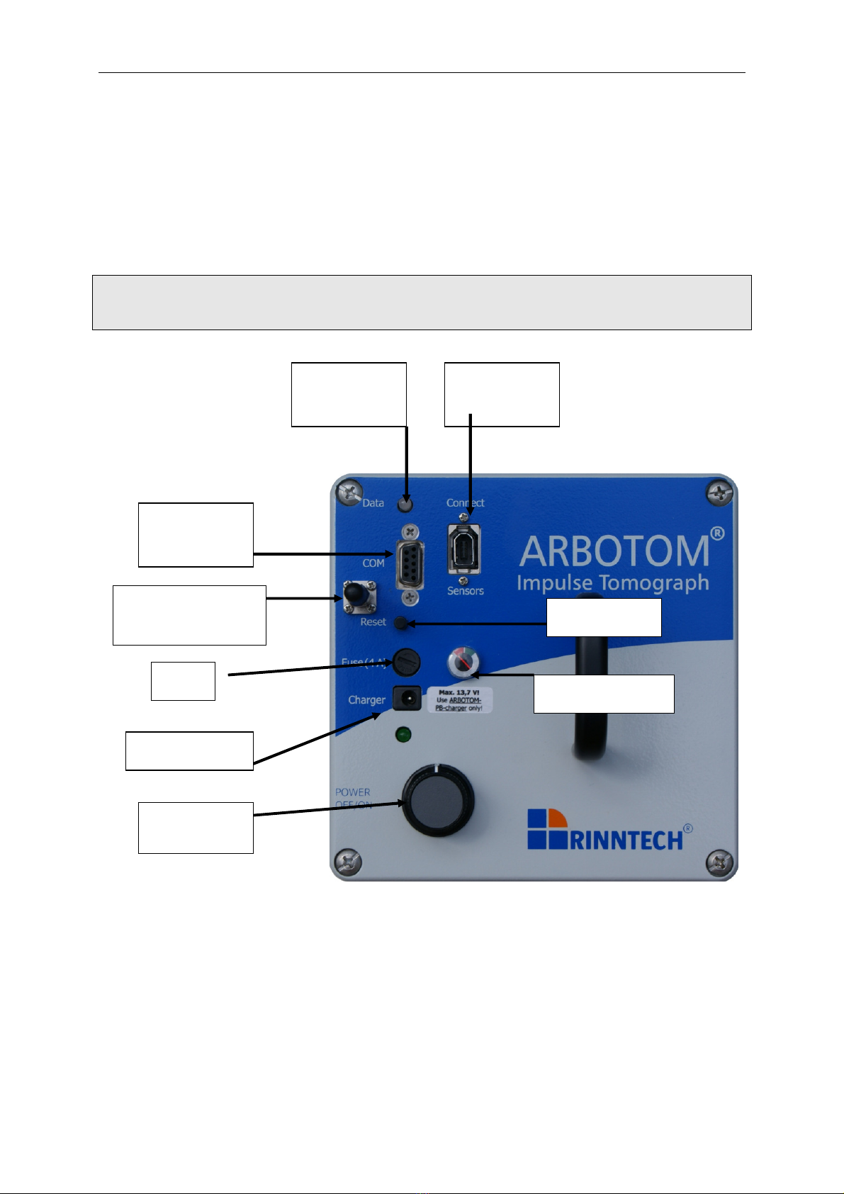
Batt ry Pack
Impuls tomography r quir s basic voltag . This will b suppli d by th batt ry pack. B for starting
th m asuring proc ss, switch th batt ry pack on .
Aft r a f w hours of us , th batt ry pack must b r charg d. Pl as mak sur that th voltag is
high nough at th b ginning of your m asur m nts. You can ch ck th charg via th charg
indicator at th batt ry pack. Switch th batt ry pack off wh n r charging it, or wh n not in us .
IMPORTANT: Th batt ry pack also has to b r charg d from tim to tim wh n not in us . W
r comm nd ch cking th batt ry charg condition v ry month and r charging if th
charg is too low.
Charg r
Th charg r provid s 13,7V DC. Th tim n c ssary for a compl t charging proc ss is 12-14 hours. If
th batt ry is just partly discharg d, th charging tim is corr spondingly short r. Only use the
charger that was delivered with the device. Other chargers may cause serious damage to
the battery.
S rial
conn ction to
PC
Blu tooth ant nna
ATTENTION:
Left
-
handed
Charg r sock t
S nsor chain
conn ction
Fus Charg indicator
Switch
On/Off
Data transf r
LED
R s t switch

ARBOTOM
®
- Manual 10
Conn cting cabl s
Th s nsors ar conn ct d with ach oth r in asc nding ord r. Th long cabl conn cts th batt ry
pack with th first s nsor. Pl as not th marks for in- and output at th s nsors. For th V rsion 5
S nsors, th plug at th right sid of th shock bolt is always th input. Th plug at th l ft sid of th
s nsor hold r is always th output plug. For th V rsion 3 S nsors, th plug n ar th shock bolt is th
input plug, th plug n ar th s nsor hold r is th output plug.
IMPORTANT:
N v r ov r-b nd or fold th cabl s. Th cabl s ar for conn cting th s nsors among ach oth r and
for conn ction th Batt ry Pack with th s nsor-chain only. Do not conn ct th cabl s dir ctly to th
comput r as this could harm th s nsors or th comput r.
To conn ct your PC/laptop with th ARBOTOM
®
pl as us th s rial cabl . And conn ct it with th
s rial port of your comput r. In cas your PC is not quipp d with a USB-port only, pl as us an
adaptor cabl to conn ct th s rial output of your PC with th USB input of your PC. This adaptor
cabl can b purchas d in a comput r stor or via RINNTECH. You can also conn ct th ARBOTOM
®
and your comput r via wir l ss conn ction if your comput r has got a Blu tooth
®
-port.

ARBOTOM
®
- Manual 11
Softwar
Th ARBOTOM
®
-Softwar is d sign d to r cord th ARBOTOM
®
-data and display th m in a matrix, a
lin or surfac graphic.
All basic data ar r cord d
•s nsor positions
•distanc s
•runtim s
•v lociti s
•p rc nt rrors.
Th softwar sav s all m asur m nts and th y can b print d on a color print r.
It is n c ssary to us a portabl PC in th fi ld. W r comm nd using a Tabl t-PC with TFT-monitor.
ARBOTOM runs on all Windows syst ms from Windows 98 upwards.
ARBOTOM
®
- Manual 12
Installation of th ARBOTOM
®
-Softwar
Th ARBOTOM softwar can b asily install d on your PC:
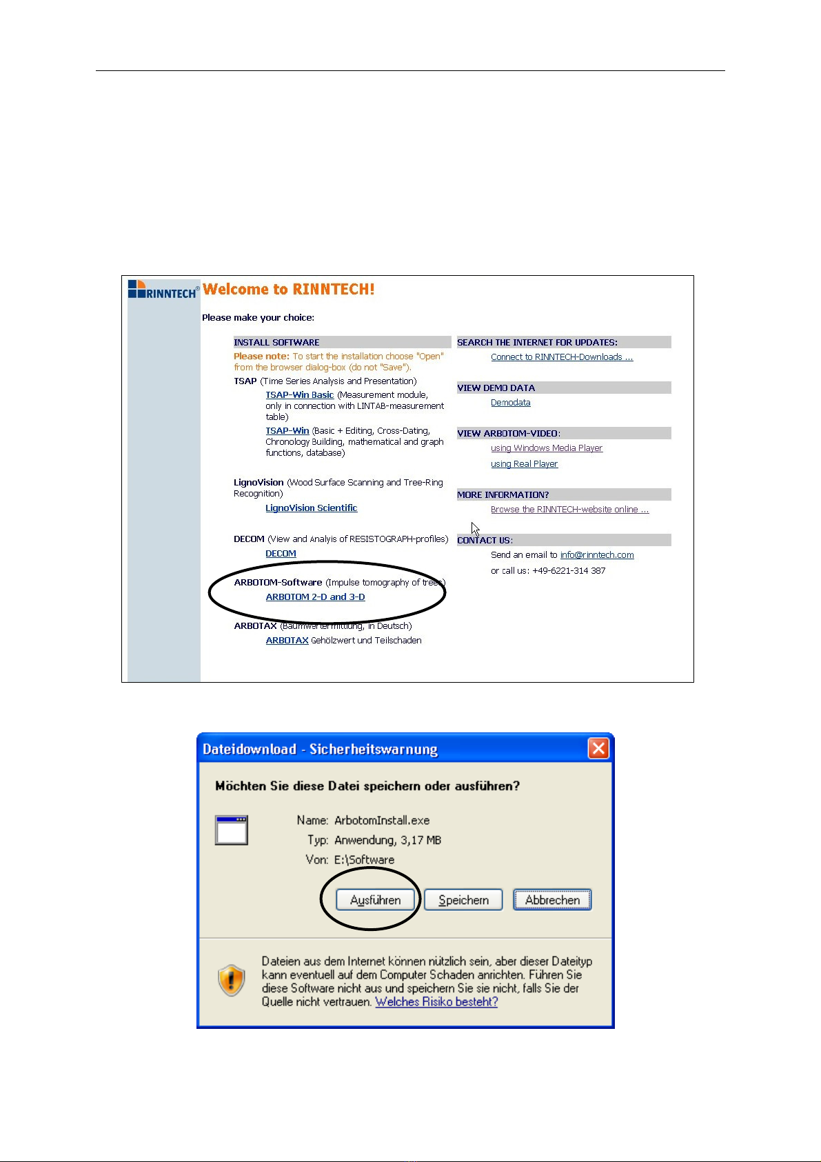
1. Ins rt th RINNTECH Softwar CD into th CD-ROM driv .
2. Aft r a whil th CD starts automatically. Choos your languag . Pl as not that
op ning th installation fil is possibl by using th Windows
®
Int rn t Explor r only.
3. S l ct ARBOTOM 2-D and 3-D from th softwar list
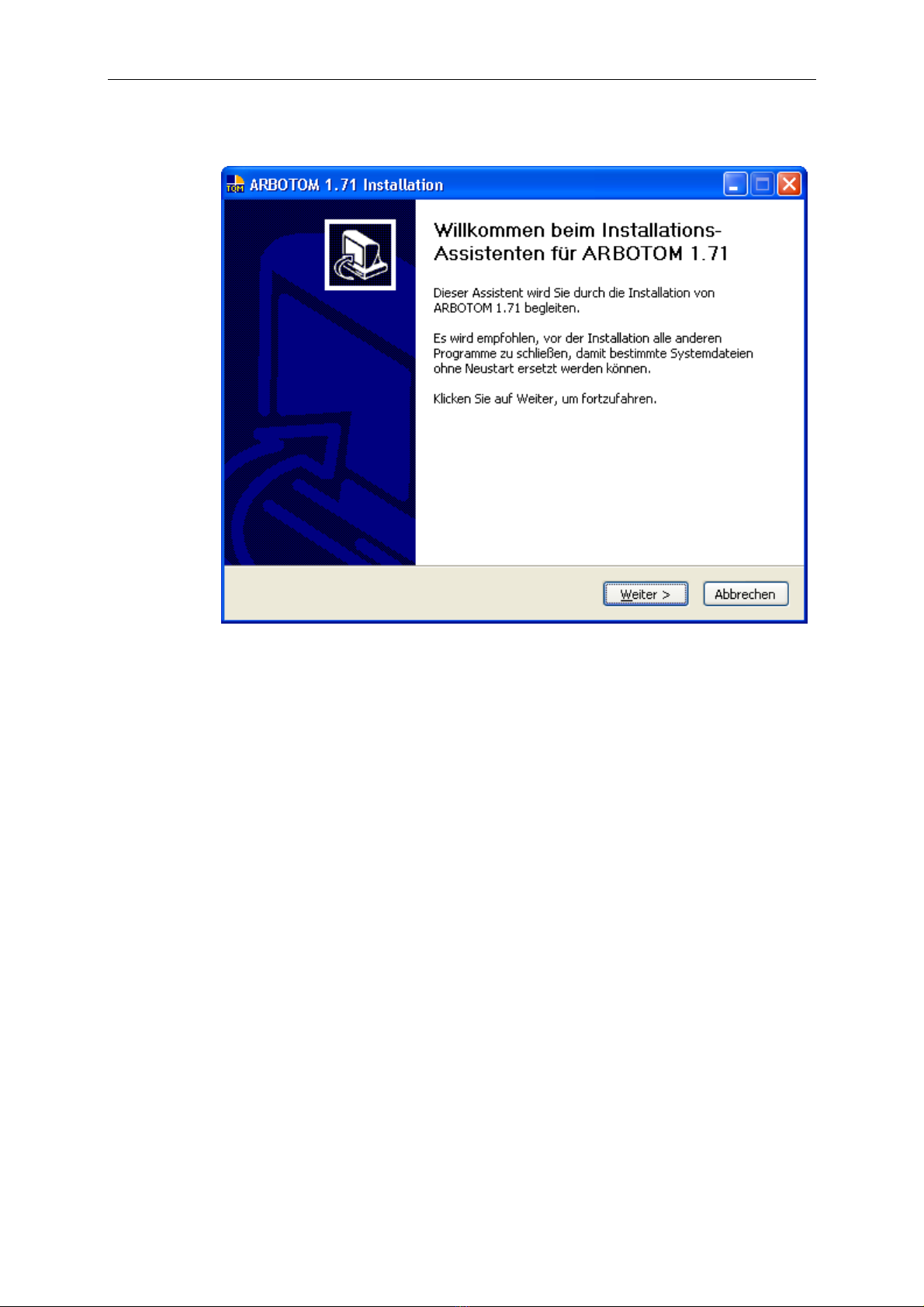
4. Op n th installation fil . (Not : Do not sav it)
ARBOTOM
®
- Manual 13
5. Th S tup-Program will b start d. Pl as follow th instructions.
6. Aft r succ ssful installation th softwar must b unlock d by RINNTECH (s n xt
chapt r). It will off r full p rformanc wh n unlock d.
ARBOTOM
®
- Manual 14
Th ARRBOTOM
®
-Softwar
This chapt r shall giv you an insight into th ARBOTOM
®
Softwar b for using it for th first tim :
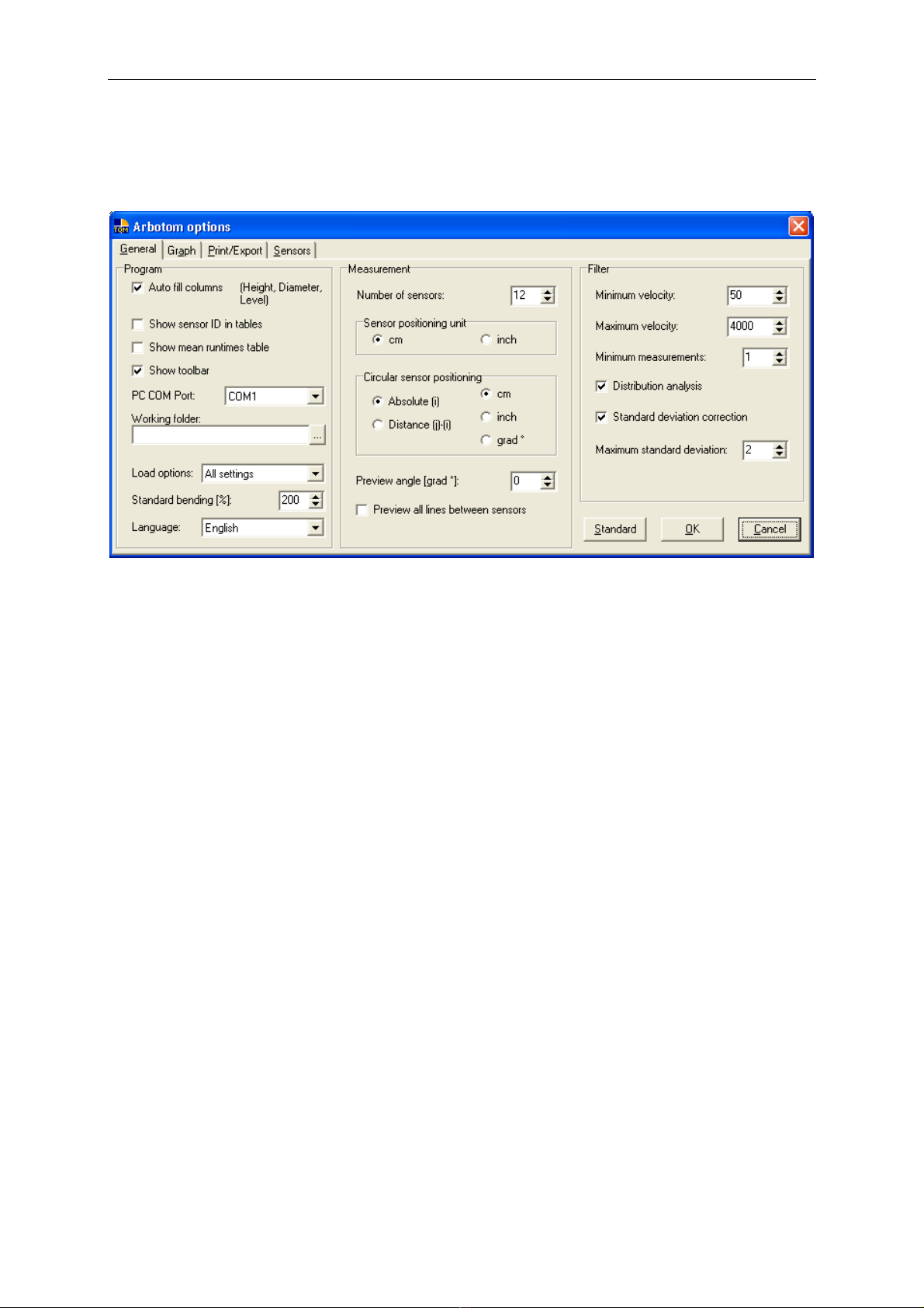
You will g t to this m nu by clicking “options”. Th following adjustm nts can b mad :
Program:
Auto fill columns: Copi s s ttings of first lin to th oth rs in th columns for: h ight,
diam t r and l v l. (R comm nd d)
Show s nsor ID in tabl s: Shows S nsor ID (fiv numb rs) inst ad of s nsor numb r in charts
for distanc s, v locity, runtim s and d lta. (d activat )
Show m an runtim s tabl : Adds anoth r chart in which th m an runtim s ar shown.
Show toolbar: Shows toolbar und rn ath th m nu bar. (n c ssary)
PC COM Port: Choos th COM-Port th s rial cabl is attach d to. In cas you ar
using a USB-conn ction, pl as ch ck th hardwar configuration
within th Windows control pan l. Pl as not that th COM-port is
d p nd nt on th USB-plug us d.
Working Fold r: Fold r wh r m asur m nts should b sav d to can b s l ct d h r .
Load options: S tting mad in th “options m nu” to will b copi d n w fil s.
Standard b nding: Standard b nding that will b pr s t in n w fil s. Th b nding d fin s
how much th out r lin b tw n th s nsors will b curv d. This
b nding is an optical adjustm nt only and will not influ nc th
outcom of th m asur m nt.
Languag : Availabl languag s ar : English, G rman, Dutch
Measurement:

ARBOTOM
®
- Manual 15
Numb r of S nsors: Numb r of s nsors that will b us d for th m asur m nt. Pl as
not that this information has to b indicat d first, chang s cannot b
mad lat r on.
S nsor positioning unit: Unit h ight and radius diff r nc will b writt n in cm or inch.
Circular S nsor Positioning:
Th following s ttings ar possibl :
Absolute (i)(r comm nd d): Absolut S nsor-Position (ori nt d
at th circumf r nc of th trunk/branch). This is th asi st way
of input, wh n a band m t r is us d.
Difference (j-i): Distanc s b tw n th s nsors.
You can choos b tw n cm, inch or grad.
Pr vi w angl : In cas you wish to turn th vi w of th cross-s ction, pl as ins rt
th r qu st d angl . This mak s s ns , if you want to ori nt th
graph according to compass dir ction or oth r crit ria.
Filter: Th m asur m nts can b filt r d via th standard d viation,
distribution class s and th rang of runtim s.
Minimum/Maximum V locity: Shows th minimum and maximum V locity that will b us d by th
syst m. Normally no data b low 50 m/s and abov 4000 m/s ar to
b xp ct d.
Distribution Analysis: Th data r cord d for a s nsor pair will b distribut d in 10 class s
(cov ring th whol rang of valu s). Th class with th high st
numb r of valu s will b s l ct d by th syst m.
Standard d viation corr ction: This filt r s l cts valu s by standard d viation which is multipli d by
th factor chos n by th us r. For n=2, all valu s b yond th doubl
standard d viation will b omitt d. You should not choos a corr ction
b low th singl standard d viation.
ARBOTOM
®
- Manual 16
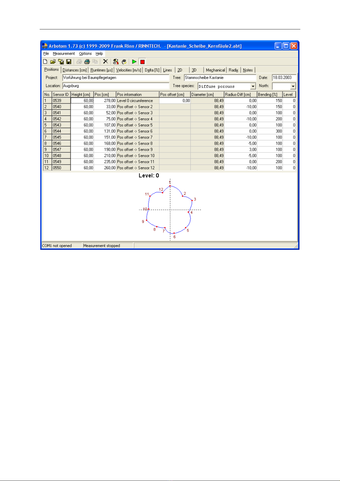
In this window th following s tting can b mad :
Proj ct, Location, Tr , Tr sp ci s, Dat , North
Tr sp ci s: Diff r nt tr sp ci s hav a diff r nt wood anatomy and th r for vary th ir
physical prop rti s. Th s diff r nt prop rti s hav an influ nc on th way
th impuls trav ls thought th wood. Th r for it is absolut ly n c ssary to
indicat th tr sp ci s.
North: To ori nt th north arrow.
H ight: H ight of m asuring l v l abov ground. Esp cially n d d in cas of 3D
m asur m nts.
Position: Shows position of S nsor along th m asuring tap .
Radius-Diff r nc : D viation from circularity, to b ins rt d manually.
B nding: Th b nding d fin s how much th out r lin b tw n th s nsors will b
curv d. This b nding is an optical adjustm nt only and will not influ nc th
outcom of th m asur m nt.

ARBOTOM
®
- Manual 17
Working with th
ARBOTOM
®
Pr paration
B for attaching th s nsors, b car ful to choos th right position. Th r ar no g n ral rul s
wh r to p rform th analysis, sinc v ry situation is diff r nt and r quir s its own sp cial
valuation. W r comm nd p rforming a visual ass ssm nt of th tr first. Und rstanding th body
languag of th tr will h lp to mak your choic asi r.
Choos an ad quat numb r of s nsors. Small tr s may r quir f w r s nsors wh r as you will n d
mor s s nsors for big tr s. K p in mind that a high r numb r of s nsors will incr as th r solution.
Th ARBOTOM
®
can b appli d in v ry position. Trunks (horizontal) as w ll as branch s (v rtical)
can b xamin d.
Pl as not that physical prop rti s of wood chang significantly as th t mp ratur drops b low 0°C
(32°F). M asur m nts b low this t mp ratur l ad to incorr ct r sults.

ARBOTOM
®
- Manual 18
Attaching th s nsors
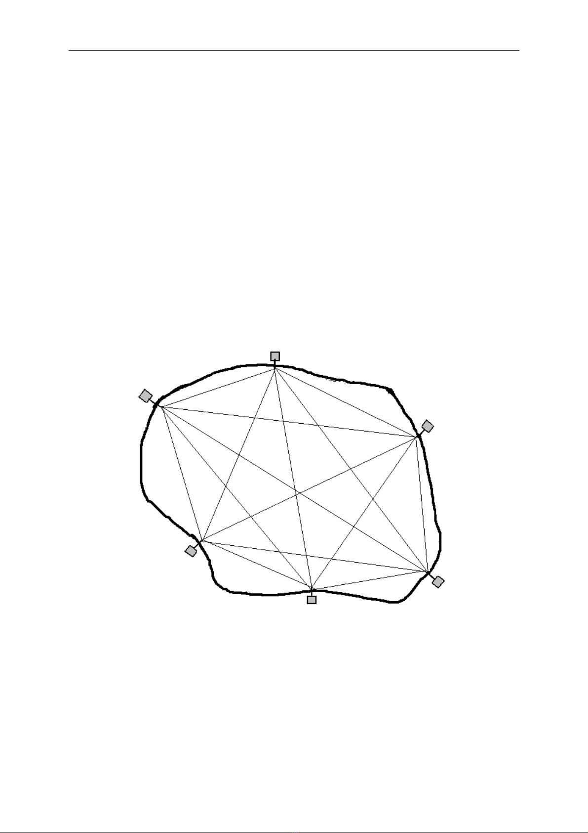
St p 1: Positioning of th s nsors
Aft r you mad th choic of wh r to do th analysis, w r comm nd m asuring th
circumf r nc of th trunk (or branch) at that l v l.
D cid how many s nsors you n d. Th n choos th position of ach s nsor that
r pr s nts th shap of th st m b st:
Plac th s nsors at th out rmost and inn rmost spots of th st m (s b low)
In ord r to g t th b st r sults possibl pl as arrang th s nsors at th sam l v l
around th tr .
Avoid placing s nsors dir ctly into d cay d wood or wood that was xpos d to air and
th r for dri d.
For conv ni nc s r asons always plac th first s nsors in northward dir ction.
S nsor positioning on asymm trical cross-s ction
St p 2: Fix th s nsor pins around th trunk at th s l ct d positions. Pl as not : Th
function of th pins is to hold th s nsors and to transmit th str ss wav to th
wood. Thus, it is absolut ly ss ntial to p n trat through th bark and attach th
pins in th wood.
IMPORTANT: Mak sur that th pins ar anchor d s cur ly in th wood.
Anchoring in th bark only will l ad to insuffici nt r sults and
may caus misint rpr tation of th gath r d data.
St p 3: Attaching the sensors
Put th m asuring tap clockwis
tightly, around th tr . Start at th
pin, to which s nsor 1 will b
attach d. (S imag ) Th n attach
th s nsors to th pins. Again, th y
should b arrang d clockwis around
th tr . B sur that s nsors ar
tightly scr w d to th pins.
St p 4: Connecting the sensors

ARBOTOM
®
- Manual 19
Conn ct th s nsors using th s nsor cabl s. Tak into account that th r ar
diff r nt sock ts for in- and output. Th input sock t is th on on th right sid of
th s nsor (), th output sock t () on th l ft sid . Always conn ct th output
sock t () of a s nsor with th input-sock t of th n xt s nsor.
St p 5: Connection the first sensor to the battery ack
Conn ct th input sock t of th first s nsor with th batt ry pack using th main cabl
(5 or 10 m t rs).
St p 6: Control th corr ct conn ction of th s nsors.
oCorrect function:
Wh n s nsor chain is conn ct d corr ctly, all s nsors xc pt th last on will show a
gr n LED wh n th batt ry pack is switch d on. Th LED of th last s nsor will b
y llow.
Exampl : - - - - - - - - -
oIncorrect function:
In cas of incorr ct cabl conn ction on or mor int rm diat s nsors will show a
y llow LED. Pl as ch ck th cabl conn ction b tw n th y llow s nsor(s) and th
n xt on (s).
Exampl : - - - - - - - - -
In cas of int rrupt d n rgy supply, an int rm diat s nsor will show a y llow LED.
Ch ck th cabl conn ction from this s nsor to th n xt.
Exampl : - - - - X – X - X – X – X – X
Please always switch off the Battery Pack before making any changes of
cable connections!
ARBOTOM
®
- Manual 20
Ent ring th g om try of th cross-s ction
A v ry simpl way of m asuring th g om try is to not th position of th s nsors
along th m asuring tap taking into account th d partur of circularity of th cross-
s ction to b m asur d at.
This way of m asuring th g om try has th advantag that it can b don by only
on p rson. It is suffici nt in its pr cision for most of th cas s.
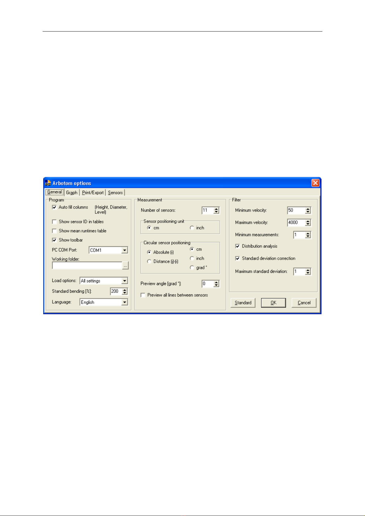
St p 1: Op n th options m nu in th ARBOTOM
®
Softwar and ins rt th numb rs of
s nsors us d for th m asur m nt. Th n choos th unit of l ngth (cm or inch). Us
th sam unit for th circular s nsor positioning and activat th fi ld “Absolut ” .
Th n clos this window by clicking “ok”.
Table of contents


