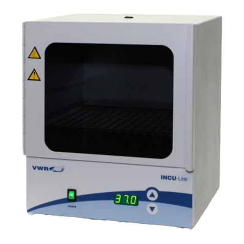
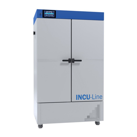
VWR INCU-Line Tower User manual

EN 1
Cooled Incubator
VWR INCU-Line Tower
INSTRUCTION MANUAL
European Catalogue Number:
390-0963 INCU-Line Tower
Version: 2
Issued: 14.08.2017

EN 2
Legal Address of Manufacturer
Europe
VWR International bvba
Researchpark Haasrode 2020
Geldenaaksebaan 464
B-3001 Leuven
+ 32 16 385011
http://be.vwr.com
Country of origin: SLOVENIA

EN 3
Table of Contents
Warning ...........................................................................................................................4
Safety information............................................................................................................4
Package Contents ...........................................................................................................4
Unpacking........................................................................................................................4
Installation........................................................................................................................5
Intended Use ...................................................................................................................5
Symbols and conventions................................................................................................5
Product specifications......................................................................................................5
Overview..........................................................................................................................6
Description of front panel.................................................................................................6
Instructions for use ..........................................................................................................7
Getting started ...........................................................................................................................7
Operation ...................................................................................................................................7
Temperature re-adjustment .......................................................................................................7
Troubleshooting ...............................................................................................................8
Cleaning and maintenance ..............................................................................................8
Accessories .....................................................................................................................8
Technical Service ............................................................................................................9
Warranty ..........................................................................................................................9
Compliance with local laws and regulations.....................................................................9
Equipment disposal .........................................................................................................9
Appendix........................................................................................................................10
Your Distributor..............................................................................................................12

EN 4
Warning
Configuring and operating this equipment requires precise knowledge and observance of the instructions
in this user manual. The equipment is designed only for its intended application.
Important safety symbols used in this manual:
Warning!
This is a warning of risk situations and dangers. Failure to observe this warning could be
life-threatening. These warnings must be heeded.
This equipment is designed for 230V (50/60Hz).
Make sure it is connected to the correct power supply.
Disconnect the power cord before carrying out maintenance or cleaning work.
Safety Information
The responsibility for operating the equipment lies exclusively with the owner or user if said equipment is
incorrectly serviced, maintained or altered by persons not employed by an authorized dealer, or if the
equipment is used in a manner contrary to its specified purpose.
The equipment must be maintained and operated in accordance with this user manual.
Ensure that this user manual is accessible at all times and has been read and understood.
To avoid electric shock do not spill any liquids on the equipment.
Package Contents
Description Quantity
Cooled Incubator INCU-Line Tower 1
Stainless steel shelf 4
Power cord 1
Test certificate 1
Unpacking
Carefully inspect the unit and accessories thoroughly upon receipt for any damage that may have occurred
during shipping. Severe damage to the packaging container may indicate damage to the unit. If you suspect
damage to the unit, immediately file a claim with the carrier in accordance with their instructions before
contacting VWR. Also verify that all accessories are included and that the unit is in good working order
before discarding the shipping packaging.

EN 5
Installation
Your satisfaction and safety require a complete understanding of this unit. Read the
instructions thoroughly and be sure all operators are given adequate training before
attempting to put the unit in use.
NOTE: This equipment must be used only for its intended application; any alterations or
modifications will void your warranty and may cause injury.
Intended use
VWR INCU-Line Tower is a general purpose convection incubator with two separate chambers, capable of
uniformly cooling and heating samples from 10 ºC below ambient up to a maximum of 50 ºC. The unit has
two transparent doors, so samples can be observed without opening the doors, thus preventing temperature
changes in the chambers.
For research use only. Not intended for any animal or human therapeutic or diagnostic use.
Symbols and conventions
The following chart is an illustrated glossary of the symbols that are used in this manual.
CAUTION
This symbol indicates a potential risk and alerts you to proceed with caution.
Product Specifications
Specifications INCU-Line Tower
Electrical 230 V, 50/60 Hz, 0.7 A
Maximum total power consumption 160 W
Power consumption per chamber at 15 ºC 65 W
Power consumption per chamber at 37 ºC 35 W
Power consumption per chamber at 50 ºC 60 W
Fuses 2 x 2 AT 250 V
Controls PID control
Temperature range Ambient -10 ºC to +50 ºC
Temperature resolution (display) 0.1 ºC
Temperature accuracy at 37 ºC ± 0.5 ºC
Temperature fluctuation (time) at 37 ºC ± 0.2 ºC
Temperature variation (spatial) at 37 ºC ± 1.0 ºC
Environment temperature +15 ºC to +40 ºC
Interior volume 2 x 23 l
Maximum load per shelf 3 kg
Maximum load per chamber 9 kg
Exterior dimensions W x D x H 380 x 470 x 790 mm
Interior dimensions W x D x H 294 x 300 x 270 mm (each chamber)
Weight 34 kg

EN 6
Overview
The INCU-Line Tower cooled incubator has two chambers - upper and lower. Temperature is individually
controlled.
Access port (Ø 7 mm) for external temperature probe
Description of front panel
The front panel is divided in two parts by a wave line. Display and keys on the left side (above the wave line)
are used to control the upper chamber. Display and keys on the right side (below the wave line) are used to
control the lower chamber.
Power switch turns the power ON and OFF for both chambers. If you use only one chamber, you can turn
the other chamber OFF by simultaneously pressing the corresponding UP and DOWN keys.
POWER - power switch: For turning the incubator ON and OFF. It lights when the incubator is switched ON.
▲- UP key: For increasing the set-temperature.
▼- DOWN key: For decreasing the set-temperature.
Display: For displaying the actual temperature (dot blinks when you change the set temperature).

EN 7
Instructions for use
Getting Started
Check the data plate for voltage, cycle, wattage and ampere requirements. If matched to your power source,
plug the power cord into a grounded outlet. Voltage should not vary more than 10 % from the data plate
rating.
In selecting a location, consider all conditions which might affect performance, such as heat from radiators,
autoclaves, etc. Avoid direct sun, fast-moving air currents, heating/cooling ducts and high traffic areas. Allow
a minimum of 50 mm between the unit and walls or partitions which might obstruct free airflow.
Operation
Do not use this incubator in explosive or flammable environments. Do not heat or incubate
flammable, explosive or highly reactive materials in this incubator as serious injury may
result.
Place the unit on a level surface and plug the unit into a properly grounded outlet of appropriate voltage.
Install the shelves into both chambers, at the desired height, with the shelf edges up. If you intend to place
the samples on the bottom of the chamber, install the shelf so that it sits with the edges down on the
chamber bottom, thus creating an air gap between the chamber bottom and your samples.
Place the samples in one or both chambers and close the doors. Make sure that both doors are securely
closed.
Turn the power switch to the ON position. The switch should illuminate. On both displays all "888" are
displayed at first, then software version "VX.X", and then the current temperatures for both chambers.
Incubator starts to cool or to heat individual chambers independently, regarding to the set temperature for
each chamber.
Display and keys on the left side (above the wave line) are used to control the upper chamber. Display and
keys on the right side (below the wave line) are used to control the lower chamber.
Set desired temperature for each chamber with the corresponding UP or DOWN key. You must press and
hold the UP or DOWN key for more than 2 seconds, until the DOT on the DISPLAY starts to blink. When the
DOT starts to blink (it blinks for 3 seconds), set the temperature to the desired value, between 10 ºC below
ambient and up to a maximum of 50 ºC. When the desired temperature is set, the display will automatically
show the current temperature after 3 seconds (DOT stops to blink).
You can always display the SET temperature by pressing and holding the relevant UP or DOWN key for
more than 2 seconds.
If you want to use only one chamber, you can turn the other chamber OFF by simultaneously pressing (short
press) the corresponding UP and DOWN keys. Message "OFF" appears on the display to indicate that the
chamber is turned OFF. When you want to use the chamber again, turn it ON by simultaneously pressing
(short press) the corresponding UP and DOWN keys. Current temperature appears on display and cooling or
heating of the chamber starts.
Temperature readjustment
Perform the following procedure individually for each chamber.

EN 8
The incubator has software for temperature readjustment. You must first measure the temperature in the
middle of the chamber or in the sample for a minimum of 2 hours. You must measure the temperature with a
certificated reference temperature measuring instrument with 0.1 ºC precision or better. After 2 hours or
more read the temperature on a thermometer and compare it with the temperature on the LED display.
Difference between thermometer and display is the value that you will enter in the software.
You can insert the thermometer into the upper chamber through the opening on the top of the incubator, and
into the lower chamber through the opening on the left side of the incubator.
Example 1: Reference temperature is 37.9 ºC, temperature on display is 37 ºC. Difference is 37.9 - 37 = 0.9
Value is 0.9 (value which you enter in the software).
Example 2: Reference temperature is 36.2 ºC, temperature on display is 37 ºC. Difference is 36.2 - 37 = -0.8
Value is - 0.8 (value which you enter in the software).
Procedure for temperature readjustment:
Press the UP and DOWN keys simultaneously for more than 5 seconds (while current temperature is
displayed on display) - message "COr" (correction) appears on display and the DOT starts to blink.
With the relevant UP or DOWN key set the value (while DOT is blinking). Pay attention to the sign of the value
(plus or minus). After 3 seconds, when you have set the temperature, display will automatically show the
current temperature.
Troubleshooting
Review the information in the table below to troubleshoot operating problems.
Display Cause Solution
Er1 Temperature probe fault, electronic board
fault or incorrect setting of parameters.
Contact your distributor.
Er4 Overheating of the electronics. Turn the main switch off and wait for the
device to cool down. Then you can use the
incubator again.
Cleaning and maintenance
Prior to any cleaning or maintenance of the unit, disconnect the power cord from the wall
outlet.
When you are using the unit for cooling, some drops of water could condense on the inside of the chambers.
Use a soft cloth to wipe the inside of the chambers, if necessary.
Clean the unit internally and externally with a damp cloth and mild soap. Do not immerse the unit or spill
liquids into or on the unit. Use of alcohol or ammonia-based cleaners on the door may cause it to crack.
Allow the incubator to dry completely inside and outside, before reconnecting the power and using it again.
Accessories
Description Quantity Cat. No.
Extra shelf, 286 x 285 mm, stainless steel 1 390-0483
Tube rack, 2 x 6 positions, Ø 32 mm 1 390-0386

EN 9
Technical service
Web Resources
Visit the VWR's website at www.vwr.com for:
• Complete technical service contact information.
• Access to VWR's Online Catalogue, and information about accessories and related products.
• Additional product information and special offers.
Contact us
For information or technical assistance contact your local VWR representative or visit www.vwr.com.
Warranty
VWR International warrants that this product will be free from defects in material and workmanship for a
period of two (2) years from date of delivery. If a defect is present, VWR will, at its option and cost, repair,
replace, or refund the purchase price of this product to the customer, provided it is returned during the
warranty period. This warranty does not apply if the product has been damaged by accident, abuse, misuse,
or misapplication, or from ordinary wear and tear. If the required maintenance and inspection services are
not performed according to the manuals and any local regulations, such warranty turns invalid, except to the
extent, the defect of the product is not due to such non-performance.
Items being returned must be insured by the customer against possible damage or loss. This warranty shall
be limited to the aforementioned remedies. IT IS EXPRESSLY AGREED THAT THIS WARRANTY WILL BE
IN LIEU OF ALL WARRANTIES OF FITNESS AND IN LIEU OF THE WARRANTY OF MERCHANTABILITY.
Compliance with local laws and regulations
The customer is responsible for applying for and obtaining the necessary regulatory approvals or other
authorizations necessary to run or use the Product in its local environment. VWR will not be held liable for
any related omission or for not obtaining the required approval or authorization, unless any refusal is due to
a defect of the product.
Equipment disposal
This equipment is marked with the crossed out wheeled bin symbol to indicate that this equipment must not
be disposed of with unsorted waste.
Instead it's your responsibility to correctly dispose of your equipment at lifecycle-end by handling it over to an
authorized facility for separate collection and recycling. It's also your responsibility to decontaminate the
equipment in case of biological, chemical and/or radiological contamination, so as to protect from health
hazards the persons involved in the disposal and recycling of the equipment.
For more information about where you can drop off your waste of equipment, please contact your local
dealer from whom you originally purchased this equipment.
By doing so, you will help to conserve natural and environmental resources and you will ensure that your
equipment is recycled in a manner that protects human health.
Thank you

EN 10
Appendix

EN 11

EN 12
Your Distributor
Austria
VWR International GmbH
Graumanngasse 7
1150 Vienna
Tel.: +43 01 97 002 0
Email: info[email protected]
Belgium
VWR International bvba
Researchpark Haasrode 2020
Geldenaaksebaan 464
3001 Leuven
Tel.: +32 016 385 011
China
VWR International China Co., Ltd
Shanghai Branch
Room 256, No. 3058 Pusan Road
Pudong New District
Shanghai 200123
Tel.:+86-21-5898 6888
Fax:+86-21-5855 8801
Czech Republic
VWR International s. r. o.
Veetee Business Park
Pražská 442
CZ - 281 67 Stříbrná Skalice
Tel.: +420 321 570 321
Denmark
VWR International A/S
Tobaksvejen 21
2860 Søborg
Tel.: +45 43 86 87 88
Finland
VWR International Oy
Valimotie 9
00380 Helsinki
Tel.:+358 09 80 45 51
France
VWR International S.A.S.
Le Périgares – Bâtiment B
201, rue Carnot
94126 Fontenay-sous-Bois cedex
Tel.: 0 825 02 30 30* (national)
Tel.: +33 (0) 1 45 14 85 00
(international)
* 0,18 € TTC/min
Germany
VWR International GmbH
Hilpertstraße 20a
D - 64295 Darmstadt
Freecall: 0800 702 00 07
Tel.: +49 (0) 6151 3972 0
(international)
Hungary
VWR International Kft.
Simon László u. 4.
4034 Debrecen
Tel.: +36 (52) 521-130
India
VWR Lab Products Private Limited
No.139. BDA Industrial Suburb,
6th Main, Tumkur Road, Peenya Post,
Bangalore, India – 560058
Tel.: +91-80-28078400
Email: vwr_india@vwr.com
Ireland / Northern Ireland
VWR International Ltd / VWR
International (Northern Ireland) Ltd
Orion Business Campus
Northwest Business Park
Ballycoolin
Dublin 15
Tel.: +353 01 88 22 222
Italy
VWR International S.r.l.
Via San Giusto 85
20153 Milano (MI)
Tel.: +39 02-3320311
The Netherlands
VWR International B.V.
Postbus 8198
1005 AD Amsterdam
Tel.: +31 020 4808 400
Norway
VWR International AS
Haavard Martinsens vei 30
0978 Oslo
Tel.: +47 22 90 00 00
Poland
VWR International Sp. z o.o.
Limbowa 5
80-175 Gdansk
Tel.: +48 058 32 38 200
Portugal
VWR International –
Material de Laboratório, Lda
Centro Empresarial de Alfragide
Rua da Indústria, nº 6
2610-088 Alfragide
Tel.: +351 21 3600 770
Email: info[email protected]
Singapore
VWR Singapore Pte Ltd
18 Gul Drive
Singapore 629468
Tel: +65 6505 0760
Spain
VWR International Eurolab S.L.
C/ Tecnología 5-17
A-7 Llinars Park
08450 - Llinars del Vallès
Barcelona
Tel.: +34 902 222 897
Sweden
VWR International AB
Fagerstagatan 18a
163 94 Stockholm
Tel.: +46 08 621 34 00
Switzerland
VWR International AG
Lerzenstrasse 16/18
8953 Dietikon
Tel.: +41 044 745 13 13
UK
VWR International Ltd
Customer Service Centre
Hunter Boulevard
Magna Park
Lutterworth
Leicestershire
LE17 4XN
Tel.: +44 (0) 800 22 33 44

FR 1
Incubateur réfrigéré
VWR INCU-Line Tower
MANUEL D'INSTRUCTION
Numéro de catalogue Européen:
390-0963 INCU-Line Tower
Version: 2
Fait le: 14.08.2017

FR 2
Adresse du fabricant
Europe
VWR International bvba
Researchpark Haasrode 2020
Geldenaaksebaan 464
B-3001 Leuven
+ 32 16 385011
http://be.vwr.com
Pays d'origine: SLOVENIE

FR 3
Table des matières
Avertissement ..................................................................................................................4
Informations de sécurité...................................................................................................4
Contenu de l'emballage ...................................................................................................4
Déballage.........................................................................................................................4
Installation........................................................................................................................5
Utilisation prévue .............................................................................................................5
Symboles et normes ........................................................................................................5
Spécifications du produit..................................................................................................5
Vue d'ensemble ...............................................................................................................6
Description du panneau avant .........................................................................................6
Instructions pour l'utilisation.............................................................................................7
Mise en marche .........................................................................................................................7
Utilisation ...................................................................................................................................7
Re-calibrage de la température .................................................................................................7
Disfonctionnements .........................................................................................................8
Nettoyage et maintenance...............................................................................................8
Accessoires .....................................................................................................................8
Service technique ............................................................................................................9
Garantie...........................................................................................................................9
Conformité à la législation et aux réglementations locales ..............................................9
Élimination de l'équipement .............................................................................................9
Annexe...........................................................................................................................10
Votre distributeur ...........................................................................................................12

FR 4
Avertissement
L'utilisation et le réglage de cet appareil nécessite des connaissances particulières et l'observation des
instructions de ce manuel. L'appareil est conçu uniquement pour l'usage prévu.
Symboles de sécurités importants utilisés dans ce manuel:
Attention!
Ceci est un avertissement de situation à risque et de danger. Ne pas respecter cet
avertissement peut mettre votre vie en danger. Cet avertissement doit être pris en compte.
Cet appareil est conçu pour le 230V (50/60Hz).
Assurez vous de le brancher à la bonne prise d'alimentation 230V (50/60Hz).
Débrancher le câble secteur avant toute opération de nettoyage ou de maintenance.
Informations de sécurité
La responsabilité de l'utilisation de l'appareil incombe exclusivement à l'utilisateur ou au propriétaire, si
l'appareil est mal utilisé, entretenu par des personnes non qualifiées et non agrées par un distributeur officiel
ou si l'appareil est utilisé dans d'autres buts que celui prévu par le constructeur.
Cet appareil doit être entretenu et utilisé suivant les instructions du présent manuel.
Assurez vous que ce manuel soit accessible à tout moment et ait été lu et compris.
Pour éviter les chocs électriques, ne pas renverser de liquides sur l'équipement.
Contenu de l’emballage
Description Quantité
Incubateur réfrigéré INCU-Line Tower 1
Etagère en acier inoxydable 4
Cordon secteur 1
Certificat d'essai 1
Déballage
Contrôler l'appareil et les accessoires minutieusement après réception à la recherche d'éventuels
dommages qui auraient pu subvenir pendant le transport. Des dommages graves de l'emballage peuvent
indiquer des dommages à l'appareil. Si vous suspectez des dommages à l'appareil, faites une réclamation
auprès du transporteur suivant leur procédure avant de contacter VWR. Vérifier aussi que tous les
accessoires soient présent et que la machine soit en bon état de marche avant de jeter l'emballage.

FR 5
Installation
Il est requis une parfaite compréhension de l'utilisation de la machine pour votre sécurité
et votre satisfaction. Lisez les instructions avec attention et assurez vous que chaque
utilisateur ait reçu une formation adéquate au préalable avant toute utilisation de la
machine.
NOTE: Cet appareil doit être utilisé seulement dans le but prévu, toute modification ou mauvaise
utilisation supprimera la garantie et peut causer des blessures.
Utilisation prévue
VWR INCU-Line Tower est un incubateur réfrigéré à convection avec deux chambres séparées, permettant
le refroidissement ou le chauffage uniforme des échantillons de 10 ºC sous la température ambiante jusqu'à
un maximum de 50 ºC. L'unité dispose de deux portes transparentes, donc les échantillons peuvent être
observés sans ouvrir les portes, empêchant ainsi les changements de température dans les chambres.
Appareil conçu uniquement pour la recherche. Non conçu pour une thérapie ou un diagnostic sur des
humains ou des animaux.
Symboles et normes
Le tableau suivant illustre et explique les symboles utilisés dans ce manuel.
ATTENTION
Ce symbole indique un risque potentiel et vous engage à procéder avec précautions.
Spécifications du produit
Spécifications INCU-Line Tower
Alimentation 230 V, 50/60 Hz, 0.7 A
Consommation électrique maximale totale 160 W
Consommation électrique par chambre à 15 ºC 65 W
Consommation électrique par chambre à 37 ºC 35 W
Consommation électrique par chambre à 50 ºC 60 W
Fusibles 2 x 2 AT 250 V
Contrôle Régulation PID
Gamme de température Ambiante -10 ºC à +50 ºC
Résolution de la température (d'affichage) 0.1 ºC
Précision de la température à 37 ºC ± 0.5 ºC
Stabilité de la température (temps) à 37 ºC ± 0.2 ºC
Uniformité de la température (spatial) à 37 ºC ± 1.0 ºC
Température de l'environnement +15 ºC à +40 ºC
Volume intérieur 2 x 23 l
Charge maximale par étagère 3 kg
Charge maximale par chambre 9 kg
Dimensions extérieures L x P x H 380 x 470 x 790 mm
Dimensions intérieures L x P x H 294 x 300 x 270 mm (chaque chambre)
Poids 34 kg

FR 6
Vue d'ensemble
Incubateur réfrigéré INCU-Line Tower dispose de deux chambres - supérieures et inférieures. Ils sont
contrôlés individuellement.
Port d'accès (Ø 7 mm) pour sonde de température externe
Description du panneau avant
La face avant est divisé en deux parties par une ligne d'onde. Affichage et touches sur le côté gauche (au-
dessus de la ligne d'onde) sont utilisés pour contrôler la chambre haute. Affichage et touches sur le côté
droit (en dessous de la ligne d'onde) sont utilisés pour contrôler la chambre basse.
L'interrupteur d'alimentation met l'incubateur sous tension et hors tension pour les deux chambres. Si vous
utilisez une seule chambre, vous pouvez mettre hors tension l'autre chambre en appuyant simultanément
sur les touches correspondantes HAUT et BAS.
POWER - interrupteur d'alimentation: Pour mise sous tension de l'incubateur ON et OFF. Le voyant Power
s'allume lorsque l’équipement est sous tension.
▲- Touche HAUT: Pour augmenter la température.
▼- Touche BAS: Pour diminuer la température.
Afficheur: Pour afficher la température (le point clignote lorsque vous réglez la température).

FR 7
Instructions pour l'utilisation
Mise en marche
Contrôler sur la plaque signalétique les voltage, fréquence et intensité requises. Si ils correspondent à votre
installation, brancher le cordon secteur à une prise avec terre. La tension secteur ne doit pas varier de plus
de 10 % de celle indiquée sur la plaque signalétique.
Dans le choix de l'emplacement tenez compte de l'influence de l'environnement tel que les sources de
chaleurs dues aux radiateurs et autres. Eviter l'exposition directe au soleil, aux courants d'air violents, la
proximité de canalisations froides ou chaudes et les zones de circulation intenses. Laisser un minimum de
50 mm entre l'appareil et le mur pour la circulation de l'air.
Utilisation
Ne pas utiliser cet incubateur dans un environnement ou il y a des risques d'explosion ou
d'incendie. Ne pas chauffer ou incuber du matériel inflammable, explosif ou réactif, de
graves blessures peuvent en résulter.
Placez l’incubateur sur une surface plane et branchez-le à une prise secteur appropriée.
Installez les étagères dans les deux chambres, à la hauteur désirée, avec son coté supérieur vers le haut. Si
vous désirez mettre les échantillons en bas du compartiment, placez la tablette au dernier niveau de
manière à ce qu'il y ait un espace d'air entre le fond et vos échantillons.
Placer les échantillons dans l'une ou les deux chambres et fermer les portes. Assurez-vous que les deux
portes sont bien fermées.
Positionnez l'interrupteur en position marche. L'interrupteur doit s'allumer. Sur les deux affichages tous "888"
sont affichés au début, puis la version du logiciel "VX.X", puis les températures actuelles pour les deux
chambres. L'incubateur commence à refroidir ou chauffer chaque chambre individuelle de façon
indépendante, jusqu'à la température de consigne pour chaqu'une d'elles.
Affichage et touches sur le côté gauche (au-dessus de la ligne d'onde) sont utilisés pour contrôler la
chambre haute. Affichage et touches sur le côté droit (en dessous de la ligne d'onde) sont utilisés pour
contrôler la chambre basse.
Sélectionnez la température désirée pour chaque chambre avec la touche HAUT ou BAS correspondante.
Vous devez maintenir les touches haut et bas enfoncées plus de 2 secondes; jusqu’à ce que le point de
l'afficheur clignote. Quand il commence à clignoter (il clignote 3 secondes), régler la température à la valeur
désirée, entre 10 ºC au dessous de la température ambiante et jusqu'à un maximum de 50 ºC. Quand la
température désirée est programmée l'afficheur indiquera après 3 secondes la température réelle de
l'incubateur (le point s’arrête de clignoter).
Vous pouvez regarder à tout moment la température programmée en appuyant sur la touche haut ou bas
plus de 2 secondes.
Si vous souhaitez utiliser une seule chambre, vous pouvez désactiver l'autre chambre OFF en appuyant
simultanément sur (appui court) les touches correspondantes HAUT et BAS. Message "OFF" apparaît sur
l'écran pour indiquer que la chambre est éteinte. Lorsque vous souhaitez utiliser la chambre à nouveau,
allumez-la en appuyant simultanément sur (appui court) les touches HAUT et BAS correspondantes. La
température actuelle apparaît sur l'affichage et le refroidissement ou le chauffage de la chambre commence.
Re-calibrage de la température
Effectuez la procédure suivante individuellement pour chaque chambre.

FR 8
L'incubateur possède un programme pour le re-calibrage de la température. Vous devez d'abord mesurer la
température au milieu de la chambre ou sur un échantillon pendant 2 heures minimum. Vous devez prendre
cette mesure à l'aide d’un appareil certifié avec une précision de 0,1 ºC ou plus élevée. Apres 2 heures ou
plus, relever la température sur le thermomètre et comparez-la avec la température indiquée sur l'afficheur,
la différence entre les 2 températures est la valeur que vous allez entrer dans le programme.
Vous pouvez insérer le thermomètre dans la chambre supérieure à travers l'ouverture sur le dessus de
l'incubateur, et dans la chambre inférieure à travers l'ouverture sur le côté gauche de l'incubateur.
Exemple 1: La température de référence est 37,9 ºC, la température sur l'afficheur est 37 ºC, donc la
différence est 37,9 - 37 = 0,9 donc la valeur à entrer dans le programme sera de 0,9.
Exemple 2: La température de référence est 36,2 ºC, la température sur l'afficheur est 37 ºC, donc la
différence est 36,2 - 37 = -0,8 donc la valeur à entrer dans le programme sera de -0,8.
Procédure pour le re-calibrage de la température:
Appuyer sur les touches Haut et Bas simultanément et maintenez-les appuyées plus de 5 secondes (alors
que la température actuelle est affichée sur l'afficheur) - l'afficheur va indiquer "COr" (correction) et le point
va clignoter.
Pendant qu’il clignote, entrer la valeur à l'aide des touches Haut et Bas. Faites attention au signe de la
valeur (plus ou moins). 3 secondes après le réglage, l'afficheur va automatiquement montrer la température
actuelle.
Dysfonctionnements
Consultez les informations sur le tableau ci-dessous pour résoudre les problèmes de disfonctionnement.
Afficheur Cause Solution
Er1 Défaut sonde de température, défaut carte
électronique ou un réglage incorrect des
paramètres.
Contactez votre distributeur.
Er4 Surchauffe de l'électronique. Éteignez l'interrupteur principal et attendre
que l'appareil refroidisse. Ensuite, vous
pouvez utiliser à nouveau l'incubateur.
Nettoyage et maintenance
Avant toute intervention de nettoyage ou de maintenance de l'appareil, débrancher le
câble secteur de la prise secteur murale.
Lorsque vous utilisez l'appareil pour le refroidissement, quelques gouttes d'eau peuvent se condenser à
l'intérieur des chambres. Utilisez un chiffon doux pour essuyer l'intérieur des chambres, si nécessaire.
Nettoyez l'extérieur et l'intérieur de l'appareil avec un chiffon humide et du savon. Ne pas immerger l'appareil
ou verser un liquide à l'intérieur ou sur lui. Utiliser un produit à base d'alcool ou d'ammoniaque sur la porte
peut détériorer celle-ci. Laisser l'incubateur sécher complètement à l'intérieur et à l'extérieur, avant de
rebrancher l’alimentation et l'utiliser à nouveau.
Accessoires
Description Quantité Num. Cat.
Etagère supplémentaire, 286 x 285 mm, acier inoxydable 1 390-0483
Portoirs pour tubes à essais, 2 x 6 positions, Ø 32 mm 1 390-0386
Table of contents
Languages:
Other VWR Accessories manuals

VWR
VWR 89511-416 User manual

VWR
VWR avantor INCU-Line Premium Series User manual

VWR
VWR Avantor OXY 11 User manual

VWR
VWR INCU-Line Premium User manual

VWR
VWR INCU-Line 390-1346 User manual

VWR
VWR VWR51014991 User manual

VWR
VWR avantor IL 56PR Premium User manual

VWR
VWR CO2 Incubator Basic User manual

VWR
VWR Avantor VWR OPOX 11-3 User manual

VWR
VWR Thermal Shake lite User manual

VWR
VWR pHenomenal IDP 761-C User manual

VWR
VWR Flow Through User manual

VWR
VWR 2005 User manual

VWR
VWR INCU-Line IL 23R Cool User manual

VWR
VWR Incubating Mini Shaker User manual

VWR
VWR symphony 5.3 A User manual

VWR
VWR INCU-Line User manual

VWR
VWR VWR INCU-Line IL 10 User manual

VWR
VWR INCU-Line Series User manual