Rioworks SDRCB User manual

Overview
Hard ware
Installation
BIOS
Setup
BIOS Flash
Utility
Troubleshooting
SDRCB
User’s Guide

The information in this document is subject to change without notice
Arima Computer Corp. makes no warranty of any kind with regard to this
material, including, but not limited to, the implied warranties of
merchantability and fitness for a particular purpose.
Arima Computer Corp. shall not be liable for errors contained herein or for
incidental or consequential damages in connection with the furnishing,
performance, or use of this material.
Arima Computer Corp. assumes no responsibility for the use or reliability of
its software on equipment that is not furnished by Arima Computer Corp.
This document contains proprietary information that is protected by
copyright. All rights are reserved. No part of this publication may be
reproduced, transcribed, stored in a retrieval system, translated into any
language or computer language, or transmitted in any form whatsoever
without the prior written consent of Arima Computer Corp.
Copyright2000by Arima Computer Corp.All rights reserved.
RIOWORKSTM is the trademark of Arima Computer Corp.
Other products and companies referred to herein the trademarks or
registered trademarks of their respective companies or mark holders.
Printed in Taiwan
Revision Version: 1.00
Release Date: September 2000

Contents
OVERVIEW:............................................................................. I
UNPACKING..................................................................................I
FEATURES HIGHLIGHT...................................................................II
ABOUT THIS USER GUIDE.............................................................VI
GETTING HELP........................................................................... VII
SDRCB MOTHERBOARD (PICTURE)..............................................VIII
SDRCB MOTHERBOARD (LAYOUT)................................................IX
CHAPTER 1:HARDWARE INSTALLATION....................1-1
Step 1:Jumper Setting ..........................................................1-2
Step 2:Install Memory...........................................................1-5
Step 3:Install CPU................................................................1-9
Step 4:Attach Cable to Connectors......................................1-11
Step 5:Install Expansion Cards............................................1-28
Step 6:Powering on Your Computer.....................................1-29
CHAPTER 2:BIOS SETUP.................................................2-1
Section 1:Setup Categories...................................................2-5
Section 2:Main Menu............................................................2-9
Section 3:Advanced Menu..................................................2-11
3-1:SUPER IO CONFIGURATION............................................2-11
3-2:IDE CONFIGURATION....................................................2-15
3-3:FLOPPY CONFIGURATION ...............................................2-19
3-4:BOOT CONFIGURATION..................................................2-20
3-5:EVENT LOG CONFIGURATION...........................................2-23
3-6:SYSTEM HEALTH MONITORING HARDWARE.......................2-24
Section 4:Chipset Menu......................................................2-30
Section 5:PCI PnP..............................................................2-35
Section 6:Power.................................................................2-38

Section 7:Boot....................................................................2-42
Section 8:Security..............................................................2-46
Section 9:Exit.....................................................................2-49
CHAPTER 3:BIOS FLASH UPGRADE UTILITY............3-1
APPENDIX A:TROUBLESHOOTING.............................. A-1
APPENDIX B:SYMPTOM REPORT FORM................... A-5

i
Overview
Overview
Overview
Thank you for choosingthe RIOWORKSTM SDRCB high performance Server
motherboard. TheSDRCB is adual Socket-370motherboard (M/B) based on
the ATX form factor. As the latest ServerWorks LE chipset is built in the M/B,
SDRCB fully supportsIntel®500MHz-1GMHz+PIII/Coppermine FC-PGA
processor at 100/133 MHz FSB (Front Side Bus) frequency.In memory
support, SDRCB provides four sockets for the system memory.Usersjust
simply choose PC100/133,registered with ECC DIMMs as the system
memory and the total maximum memory size can be up to 4GB.Flexibility
and expandability are always concerned by RIOWORKSTM, SDRCB contains
three 32bit/33Mhz and three 64bit/66MHz PCI slots for numerous add-on
cards and provides Peer PCI transaction support to increasesystem
performance.
Other features such as onboard SCSI interface (Optional), onboard Intel®
82559 10/100 MbpsLAN port (Optional)and onboard VGAwill provide high
system capabilities thatmeet a wide range of demanding Sever applications.
Unpacking
Remove all items from the box and make sure you have these following
items:
rOne RIOWORKS SDRCB motherboard
rOne ATA /33 IDE ribbon cable
rOne 68-pin(female) SCSI cable (Optional)
rOne 50-pin SCSI cable (female) (Optional)
rOne Floppy ribbon cable
rOne bag of spare jumpers
rOne SDRCB User’s Guide
rOne CD containing drivers and utilities
rOne Onboard SCSIand LAN User’s Guide (Optional)
rDriver Disk(s) for onboard SCSI (Optional)
If you discover damaged or missing items, please contact your retailer.

ii
Overview
Overview
Features Highlight
CPU Support dual Intel
®
500MHz~1GHz+PIII/Coppermine
FC-PGA CPUs at 100/133 MHz Front Side Bus (FSB)
frequency and designed for Socket-370 technology.
Chipset Use the latest ServerWorks LE chipset in the SDRCB
M/B. As known, the LE chipset architecture is
consisted of two main components: The Champ North
Bridge (CNB30LE) and Open South Bridge
TM
(OSB4).
Because the powerful features of its components, it
can fully support the newest technologies:
64bit/66MHz PCI bus, 100/133 FSB frequency, USB
interface, Peer PCI Transaction and I
2
C Bus support
andsoon.
System
Memory
Support
SDRCB provides four DIMM sockets and supported
total systemmemory size can be from 128MB to 4GB.
A user just chooses specific PC133/100, registered
with ECC DIMMs and DIMMs support
64Mbit/128Mbit/256Mbit technology that will allow up
to 128/256/512Mbyte per two row (Double sided
DIMM) as the system memory. Please also refer to the
install memory section (Page 1-3) for further detailed
information. Also please refer to the RIOWORKS
Website for the latest memory AVL.
Expansion
Slots Contain three 32-bit PCI, three 64-bit PCI expansion
slots for 64-bit/32-bit 66MHz/33MHz add-on card. The
advantage from 64-bit/66MHz PCI technology is the
theoretical bandwidth can be up to 528MB/s. Besides
this, SDRCB also supportsPeer PCI transaction. A
PCI device on the 32bit/33MHz PCI bus can do
Memory and I/O cycles to a PCI device on the
64bit/66MHz PCI bus

iii
Overview
Overview
Onboard
VGA Chip Use ATI RAGE
TM
as the onboard VGA chip to deliver
superior 3D acceleration and comprehensive 3D
support. The features of VGA chip include a 1.2 million
triangle/S Setup engine, single-pass trilinear filtering,
six perspectively correct texturing modes, video
texturing, Gouraud and specular shading and a host of
3D special effects. As it also incorporates all the
required logic to interface gluelessly with Digital Flat
Panel monitor, it provide the lowest cost DFT ready
implementation while maintaining support for existing
VGA connector for legacy monitor support.
Onboard
SCSI
(Optional)
Use SYMBIOS 1010-66 Ultra160 chip as the onboard
SCSI controller of SDRCB. As known, SYMBIOS
1010-66 is a high performance, dual-channel,
64bit/66MHz and Ultra160 SCSI controller. It is able to
provide theoretical 160MB/s data transfer rate per
channel (320MB/s total). It is fully backward
compatible with all of the SCSI standards such as
Ultra, Ultra Wide, and Ultra2. In order to provide
flexibility and expandability, SDRCB provides three
common SCSI internal connectors for the SCSI
devices: one is “SCSI Ultra3-50 for ultra SCSI devices;
two connectors are “ULTRA3 SCSI” for Ultra160 SCSI
devices.
Onboard LAN
(Optional) Use Intel® 82559 Fast Ethernet Multifunction controller
as onboard network interface controller. Intel
®
82559
fast Ethernet Controller can provide IEEE
802.3/802.3u 10 Base-T and 100 Base-TX compatible
network environment. A user can achieve advanced
manageability of the Alert on LAN II Specification by
using thisIntel® 82559 chip.

iv
Overview
Overview
Super Multi-
I/O Provides ports and one parallel port with EPP and
ECP capabilities. UART2 two high-speed UART
compatible serial can also be directed from COM2 to
the Infrared Module for wireless connections.
Ultra DMA 33
Bus Master
IDE
Comes with an onboard PCI Bus Master IDE
controller with one connector that support two IDE
devices inone channels, supports Ultra DMA 33, PIO
Mode 3 and 4 and Bus Master IDE DMA Mode 4, and
supports Enhanced IDE devices.
Intelligent
Platform
Manage
Interface
SDRCB provides one IPMI feature connector for the
system management add-on card that is able to
provide some system important information such as
system inventory, hardware health monitoring, and so
on in the in-band/out-of-band and cross–platform
environment.
Floppy Drive Supports 3.5” (1.44MB or 2.88MB) floppy drive and
Japanese standard “Floppy 3 mode”(3.5”disk drive:
1.44MB, 1.2MB, 720KB) and LS-120 floppy disk
drives (3.5”disk drive: 120 MB). BIOS supports IDE
CD-ROM boot-up.
Enhanced
ACPI Fully implements the ACPI standard for Windows
98/NT5.0/2000 compatibility, and supports soft off.
System
Management Supports Fan Status Monitoring and Alert,
Temperature Monitoring and Alert, Voltage Monitoring
and Alert, through the onboard Hardware Monitor, and
RIOWORKSTM’“SmartWatchTM” software.

v
Overview
Overview
Desktop
Management
Interface
(DMI)
Supports DMI through BIOS, which allows hardware to
communicate within a standard protocol creating a
higher level of compatibility.
PC99
Compliant The SDRCB is fully compliant with the Microsoft PC99
specification at both the hardware and BIOS levels.
VRM Support Support VRM 8.4 specification.
Dimension Extended ATX form factor-12’x13”

vi
Overview
Overview
About This User Guide
This manual explains how to build your system withSDRCB in detail. Please
follow the proceduresof this User Manualcarefully and pay special attention
to theseicons.
IMPORTANT This icon informs you for particularly important
details regarding the setup or maintenance of
your system. While we point out the most vital
paragraphs in a chapter, you should always
read every word carefully. Failing to do so can
cause exasperation.
WARNING This icon alerted you for potential dangers
during setting up your system with SDRCB.
These warnings should not be regarded as the
whole of your safety regimen. Never forget that
computer are electronic devices and are
capable of delivering a shock. Prevent damage
to yourself and to your board: always ensure
that your system is turned off and unplugged
the power cords whenever you are working
with it ,and that you are equipped
NOTE This icon alerted you for notice during setting
up your system. It provides you can usefulalert
during setting up a new system.
TIP This icon will show you how to configure your
system with SDRCB in aneasy and simple
ways. This icon always provides some useful
description to help you configure your system.

vii
Overview
Overview
Getting Help
If a problem arises with yours system during installation or OS operating, you
should ask your dealer for help first as your system has most likely be
configured by them. They always have the best idea and quick response for
your symptoms. If your dealer is near to your locations, you should bring your
system to them to have it quickly serviced instead of attempting to solve the
problem by yourself. Besides these, RIOWORKS also providessome helpful
resources to help you.
1. Select RIOWORKS TM '’s website at www.rioworks.com and navigate to
this product page which contain links to product updates such as
Jumper settings or BIOS updates.
2. FAQ sections on RIOWORKS Website are often helpful since other
user’s questions are often your own.
3. Email us at: [email protected] and we will try to answer your questions
please fill in the symptom report form (page A-5) in order to let our
engineerssolve your problemquickly.
viii
Overview
Overview
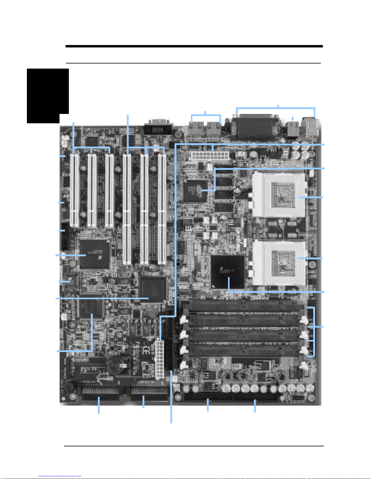
SDRCBMotherboard (Picture)
Integrated I/OConnectors
ServerWorks
CNB30LE North
Bridge
Two On-Board LAN Ports
Two USB Ports
LPT Port (Reserved)
Three 64Bit/66Mhz PCI Slots
Three 32Bit/33Mhz PCI Slots
Intel PIII
(Coppermine)
FC-PGA CPU1
Socket
Intel PIII
Coppermine)
FC-PGA CPU2
Socket
Four 25-degree
DIMM Sockets
Floppy Drive ConnectorPrimary IDE Connector
Internal 68-Pin Ultra 160
SCSI Connector (CH1)
Internal 50-Pin UltraSCSI
Connector (CH1)
Internal 68-Pin Ultra 160
SCSI Connector (CH0)
Two
ATX Power
Connectors
Onboard ATI
VGA Chip
Super I/O
Controller
SYMBIOS
Dual-Channel
Ultra160 SCSI
Controller
ServerWorks
OSB4
South Bridge
BIOS
IPMI Feature
Connector
IR Header
COM2 Header
ix
Overview
Overview
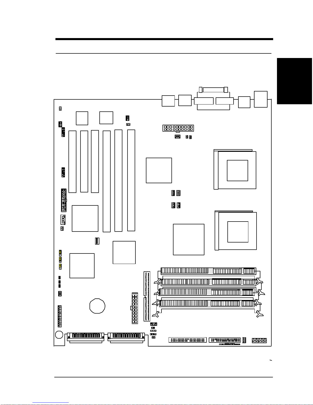
SDRCBMotherboard (Layout)
PCI 1
PCI64-1
CNB30LE
LPT
PCI 2
PCI 3
370 Socket for Intel PIII/
Coppermine FCPGA CPU
USB
Ports PS KB/
Mouse
ULTRA3-50
AUX FAN
ATX Power Connector
IDE 0
Battery
Front Panel
Connectors
IPMI Connectors
IR Connector
COM 1VGA
PGA370 PGA370
FDC
370 Socket for Intel PIII/
Coppermine FCPGA CPU
PCI64-2
PCI64-3
LAN 1
LAN 2
ATI
Rage XL
OSB4
THM 4
THM 3
BACK FAN CPU_FAN 1CPU_FAN 2
AUX FANAUX FAN
CPU 1 CPU 2
SMBUS
ULTRA3 SCSI CH0ULTRA3 SCSI CH1
AUX FAN
Buzzer
WOL WOM
COM 2
AUX FAN
THM 1
THM 2CLR_NVRAM
ACPI BUTTON CHA INTRA
SYMBIOS
1010-66
Super I/O
82559
LAN chip
(Optional)
82559
LAN chip
(Optional)
(Optional) (Optional)
(Optional)
(Optional)
(Optional)
(Optional)
Onboard VGA
DIMM1
DIMM2
DIMM3
DIMM4
FRON
T FAN
ON
CHA INTRA
USB
Slim FDC
ALARM RST
TERMO LED
FAN_LED
LAN_LED
RST_FREQ
CLR_CMOS

x
Overview
Overview
This page left intentionally blank for notes

1
Hardware
Installation
1 -
Hardware Installation
Chapter 1
Hardware Installation
In this chapter,the installation of the SDRCB with the processor and other
hardware connected to your system will be explainedin detail.
Installation Procedures
Installation procedures will be broken up into six major parts.
Step 1:Jumpersetting
Step 2: Install memory (SDRAMmemory modules)
Step 3: Install CPU
Step 4: Attach cables to connectors
Step 5: Install expansion cards
Step 6: Power connection
Warning
This motherboard contains sensitive electronic components that can
be easily damaged by static electricity. Follow the instructions carefully
to ensure correct installation and to avoid static damage.

2
1 -
Hardware Installation
Hardware
Installation
Step 1. Jumper Setting
There are three jumpersyou can use to change the setting on the
motherboard.
Item Connectors Page
1Clear Real Time Clock (RTC) RAM 1-2
2Reset Frequency 1-3
3Clear NVRAM (3-pin jumper) 1-4
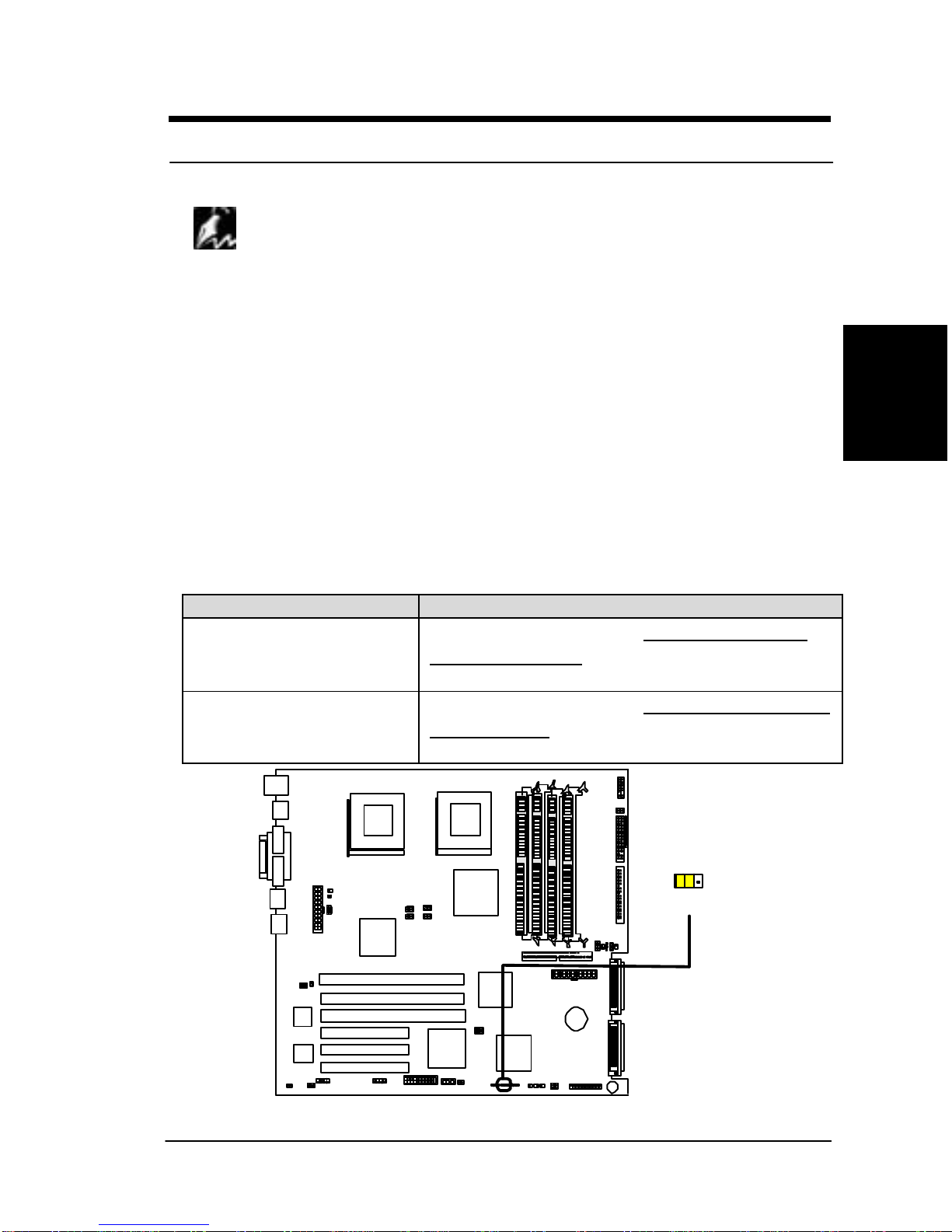
1. Clear Real Time Clock (RTC) RAM
The onboard button cell battery powers the CMOS RAM. It contains all the
BIOS setup information. Normally, it is necessary to keep the jumper
connected to pin1and pin2(Default) to retain the RTC data as shown below.
O
N
1-2:NORMAL(DEFAULT)
2-3:CLEAR
(Reserved)
1 2 3
ON
1 2 3 4 5
SDRCB CLEAR CMOS Header
3
Hardware
Installation
1 -
Hardware Installation
Note
Should you want to clear the RTC data:
(1) Soft off your computer
(2) Short pin2and pin3with jumper for few seconds
(3) Connect pin1and pin2with jumper
(4) Turn on your computer by pressing the power-on button from front-panel.
(5) Hold down <Delete> during bootup and select <Load Optimal Defaults>
or <Load Failsafe Defaults> option in the selection “Exit”. Then re-enter
BIOS setup to re-enter user preferences.
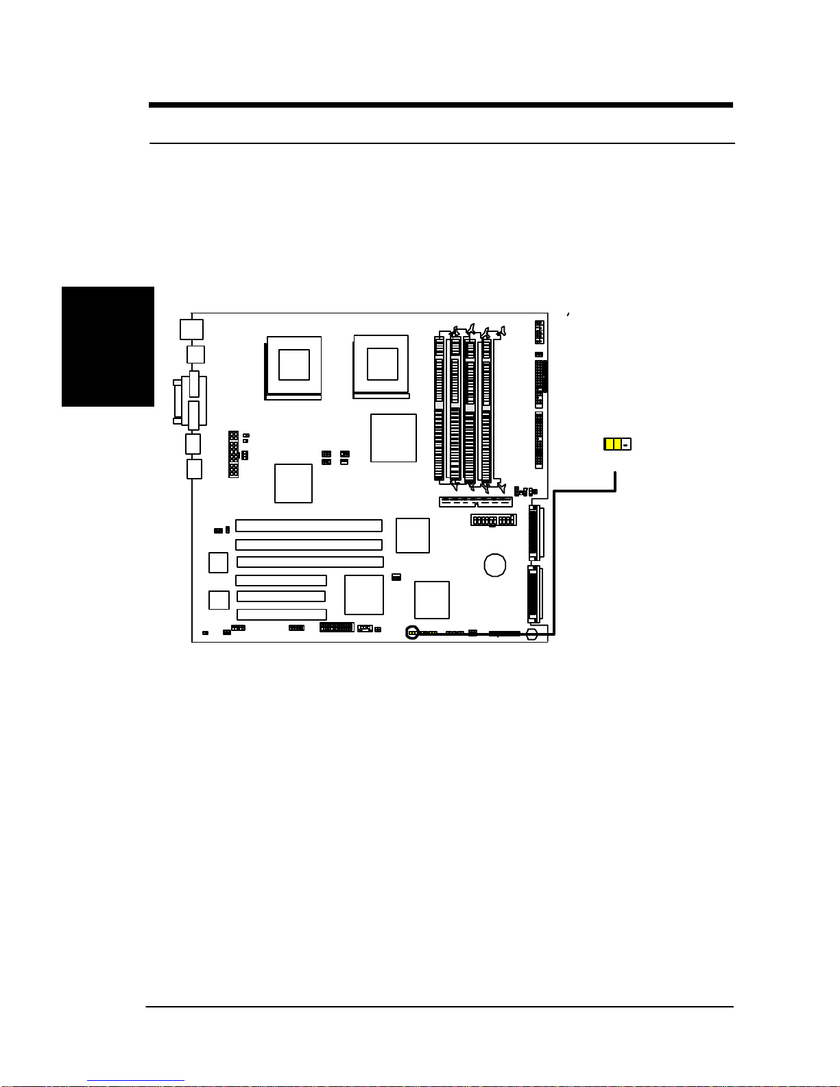
2. Reset Frequency (3-pin jumper)
This jumper allows auser to set if force the CPU ratio to fixed value (x4),
especially the system can not boot up because of Overclocking. User just
needs to short this jumper (Pin 1 and pin2) to enablethis function, then reset
the system.
CN54 Description
1-2:NORMAL (DEFAULT) The internal CPU speed =CPU FSB frequency *
ratio of BIOS Setup
2-3: SAFE MODE The internal CPU speed =CPU FSB frequency *
fixed ratio (X4).
O
N
1 2 3
1-2: NORMAL(DEFAULT)
2-3: Ratio (x4)
`
SDRCB Reset_Frequency Header
4
1 -
Hardware Installation
Hardware
Installation
3. Clear NVRAM (3-pin jumper)
When system booting up, PCI device information will be stored into the
NVRAM. When this jumper is set to “Clear” and booting up the system,
system will clear all present data stored in the NVRAM,re-scan all devices in
the PCI bus and save all new data into NVRAM.
1 2 3
1-2: NORMAL(DEFAULT)
2-3: CLEAR
O
N
SDRCB CLEAR NVRAM Header

5
Hardware
Installation
1 -
Hardware Installation
Step 2 Install Memory
SDRCB uses Dual Inline Memory Modules (DIMM).Four DIMM sockets are
available for 3.3Volts (power level),PC100/PC133,Registered and ECC
Synchronous Dynamic Random Access Memory (SDRAM) with 128MB,
256MB,512MB or 1GBcombinations. And the total memory size is between
128MB and 4GB.
IMPORTANT
qAs SDRCB has strict memory type and timing requirements. Hence,
before you attend to buy the Registered with ECC DIMM and use in
the SDRCB, please consult your local reseller for memory
suggestion first.
qUse only Intel PC133/PC100-compliant Registered with ECC
DIMMs and this motherboard operates at 133/100MHz.It will not
boot if non-compliant modules are used because of the strict
timing issues involved under this speed.
qTo utilize the chipset’s Error Checking and Correction (ECC)
features, you have to choose the DIMM module with 9 chips
(devices) per side (standard 8 chips (devices)/side plus 1 ECC chip)
and check if the setting is proper in the selection ”DRAM Integrity
Mode” in the selection “Advanced Chipset Setup” in the BIOS
Utility.
qSDRCB only support PC133/100, Registered with ECC SDRAM.
Unbuffered SDRAM and Non-ECC memory can not be used in the
SDRCB.
qSince the SDRCB memory bus is synchronized to front side bus
(FSB) speed, it is not allows a user to use PC100 DIMM with
133MHz FSBCPUin the SDRCB.Otherwise system may not able to
bootup. When a user use PC133 DIMM with 100FSB CPU, it will
result in 100MHz memory speed operation.
6
1 -
Hardware Installation
Hardware
Installation
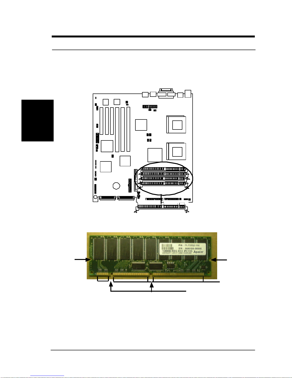
Memory Installation Procedures
1. Locate theDIMM modules on theSDRCB.
O
N
60 Pins
68 Pins 20 Pins
Tab Tab
DIMM 0
DIMM 1
DIMM 2
DIMM 3
2. Make sure the DIMM module’s pins face down and match the socket’s
size as depicted below.
Lock
Lock
DIMM Key
20 pins
60 pins
88 pins
Table of contents
Other Rioworks Motherboard manuals


 manual ")


