Rioworks SDVIA User manual

5,81)
7IAH\I/KE@A
All manuals and user guides at all-guides.com
all-guides.com

The information in this document is subject to change without notice
Arima Computer Corp. makes no warranty of any kind with regard to this material, including, but not
limited to, the implied warranties of merchantability and fitness for a particular purpose.
Arima Computer Corp. shall not be liable for errors contained herein or for incidental or consequen-
tial damages in connection with the furnishing, performance, or use of this material.
Arima Computer Corp. assumes no responsibility for the use or reliability of its software on equip-
ment that is not furnished by Arima Computer Corp.
This document contains proprietary information that is protected by copyright. All rights are reserved.
o part of this publication may be reproduced, transcribed, stored in a retrieval system, translated
into any language or computer language, or transmitted in any form whatsoever without the prior
written consent of Arima Computer Corp.
Printed in Taiwan
RIOWORKSTM is the trademark of Arima Computer Corp., 2000 All rights reserved.
All other brand and product names are trademarks or registered trademarks of their respective
companies.
Release Date: June 2000
Version: 1.0
All manuals and user guides at all-guides.com
Contents
OVERVIEW ................................................................................................................1
UNPACK YOUR SDVIA ...........................................................................................1
ABOUT THIS USER GUIDE
......................................................................................1
FEATURES HIGHLIGHT
............................................................................................2
GETTING HELP .......................................................................................................5
SDVI A MOTHERBOARD ( ICTURE) .......................................................................6
SDVI A MOTHERBOARD (LAY O U T).........................................................................7
CHAPTER 1 : HARDWARE INSTALLATION ...................................................1-1
STEP 1:JUMPER SETTINGS ..................................................................................1-2
STEP 2: INS TA LL MEMORY....................................................................................1-4
STEP 3: INS TA LL C U..........................................................................................1-7
STEP 4: ATTACH CABLE TO CONNECTORS .........................................................1-10
STEP 5: INS TA LL EXPANSION CARDS .................................................................1-21
STPE 5: OWERING ON YOUR COMPU TER ........................................................1-22
CHAPTER 2 : BIOS SETUP ................................................................................2-1
SECTION 1: SETUP ITE MS ....................................................................................2-4
SECTION 2: MAIN SETUP ......................................................................................2-6
SECTION 3: AD VANCED SETUP ..........................................................................2-10
SECTION 4: AD VANCED CHIPSET FEATURES SETUP..........................................2-15
SECTION 5: INTEGRATED ERIPHERALS.............................................................2-19
SECTION 6: OWER MANAG EMENT SETUP ........................................................2-21
SECTION 7: N / CI CONFIGURATION ..........................................................2-28
SECTION 8: LOAD FAIL SAFE / OPTI MAL SETTING .............................................2-31
SECTION 9: SECURITY........................................................................................2-33
SECTION 10: C HEALTH ..................................................................................2-34
SECTION 11: EXI T ..............................................................................................2-36
CHAPTER 3 :FLASH BIOS ................................................................................3-1
BIOS FLASH UPGRADE UTI LI TY ..........................................................................3-1
RUNNING THE ROGRAM......................................................................................3-2
COMMAND LINE ARAMETERS ..............................................................................3-3
SAV E /UPD ATE .......................................................................................................3-5
CLEAR DATA .........................................................................................................3-6
All manuals and user guides at all-guides.com

Overview
Overview
Overview
Thank you for choosing RIOWORKSTM SDVIA . The SDVIA is a dual FC- GA Socke
t
370 motherboard (M/B) based on the ATX form factor featuring the VIA apollo R
O
133A chips ets. As high performance chipsets built in the M/B, the SDVIA can supports
dual Intel® FC- GA entium III 533~1G+ MHz processor and 100/133MHz C U
Front Side Bus (FSB). In the AG bus performance, it supports AG RO/4X/2X mod
e
and pipelined spilt-transaction long-burst transfers up to 1066 MB/sec. According to
different customers requirements, SDRAM and VCM DRAM can be applied to th
e
SDVIA and the maximum memory size can be up to 2.0GB (1.5GB when FSB=133).
The on-board AMI IDE RAID controller provides the transfer rate up to 100MB/s pe
r
channel and RAID level 0 (Striping), 1 (Mirroring) and 0+1 (Striping+Mirroring)
.
Therefore, with SDVIA, people can gain higher system performance than before. Now
,
Enjoy every feature of SDVIA.
Unpack Your SDVIA
Remove all items from the box and make sure you have these items:
!" One SDVIA motherboard
!" One ATA/66 IDE ribbon cable
!" One Floppy ribbon cable
!" One bag of spare jumpers
!" One Users Guide
!" One CD containing drivers and utilities
If you discover any damaged or missing items, contact your retailer.
A
bout This User Guide
This manual explains how to build your system with SDVIA in detail. lease follow th
e
procedures carefully and pay special attention to the IMPORTANT, WARNING and
NOTE sym bols.
1
All manuals and user guides at all-guides.com
Overview
Overview
Features Highlight
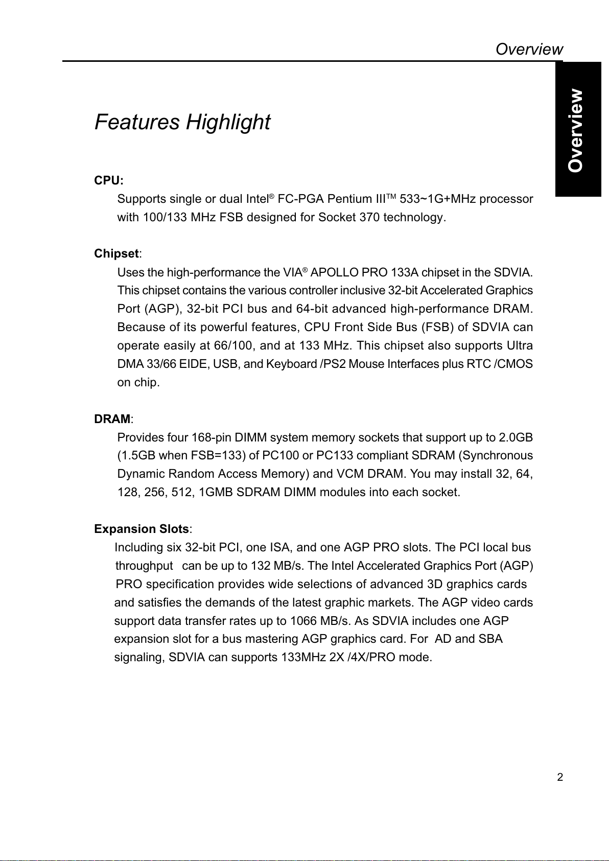
CPU:
Supports single or dual Intel® FC- GA entium IIITM 533~1G+MHz processor
with 100/133 MHz FSB designed for Socket 370 technology.
Chips t:
Uses the high-performance the VIA® A OLLO RO 133A chipset in the SDVIA.
This chipset contains the various controller inclusive 32-bit Accelerated Graphics
ort (AG ), 32-bit CI bus and 64-bit advanced high-performance DRAM.
Because of its powerful features, C U Front Side Bus (FSB) of SDVIA can
operate easily at 66/100, and at 133 MHz. This chipset also supports Ultra
DMA 33/66 EIDE, USB, and Keyboard / S2 Mouse Interfaces plus RTC /CMOS
on chip.
DRAM:
rovides four 168-pin DIMM system memory sockets that support up to 2.0GB
(1.5GB when FSB=133) of C100 or C133 compliant SDRAM (Synchronous
Dynamic Random Access Memory) and VCM DRAM. You may install 32, 64,
128, 256, 512, 1GMB SDRAM DIMM modules into each socket.
Expansion Slots:
Including six 32-bit CI, one ISA, and one AG RO slots. The CI local bus
throughput can be up to 132 MB/s. The Intel Accelerated Graphics ort (AG )
RO specification provides wide selections of advanced 3D graphics cards
and satisfies the demands of the latest graphic markets. The AG video cards
support data transfer rates up to 1066 MB/s. As SDVIA includes one AG
expansion slot for a bus mastering AG graphics card. For AD and SBA
signaling, SDVIA can supports 133MHz 2X /4X/ RO mode.
2
All manuals and user guides at all-guides.com

Overview
Overview
IDE RAID Onboard (Optional):
The AMIs IDE RAID controller supports IDE transfer rate up to 100MB/s per
channel and RAID level 0 (Striping), 1(Mirroring), 0+1(Striping+Mirroring). The
hardware RAID controller will perform the RAID functions at minimum cost of
sharing the C U bandwidth, comparing to the software RAID, and be ca-
pable of booting from RAID configured Array. It has two channels and can
connect up to four drives.
Enhanc d ACPI:
Fully implements the AC I standard for Windows 98/NT/2000TM Series
compatibility, and supports soft-off, Wake-On-Ring, Wake-On-LAN features.
Wak -On-Mod m:
Supports Wake-On-Modem activity with internal modem CI cards that con-
tain WOM connector when enable function Modem Ring Resume in the
ower Management of BIOS setup.
Wak -On-LAN:
Supports Wake-On-LAN activity with network cards that contain WOL con-
nector when enable function Modem Ring Resume in the ower Manage-
ment of BIOS setup.
Wak -On-Ring:
Supports Wake-On-Ring activity with external Modem connected with COM
port when enable function Modem Ring Resume in the ower Manage-
ment of BIOS setup.
Hardwar Monitor:
Supports Fan Status Monitoring and Alarm, Temperature Monitoring and
Alert, Voltage Monitoring and Alert, through the onboard Hardware Monitor,
and RIOWORKSTM SmartWatchTM software.
3
All manuals and user guides at all-guides.com
all-guides.com
Overview
Overview
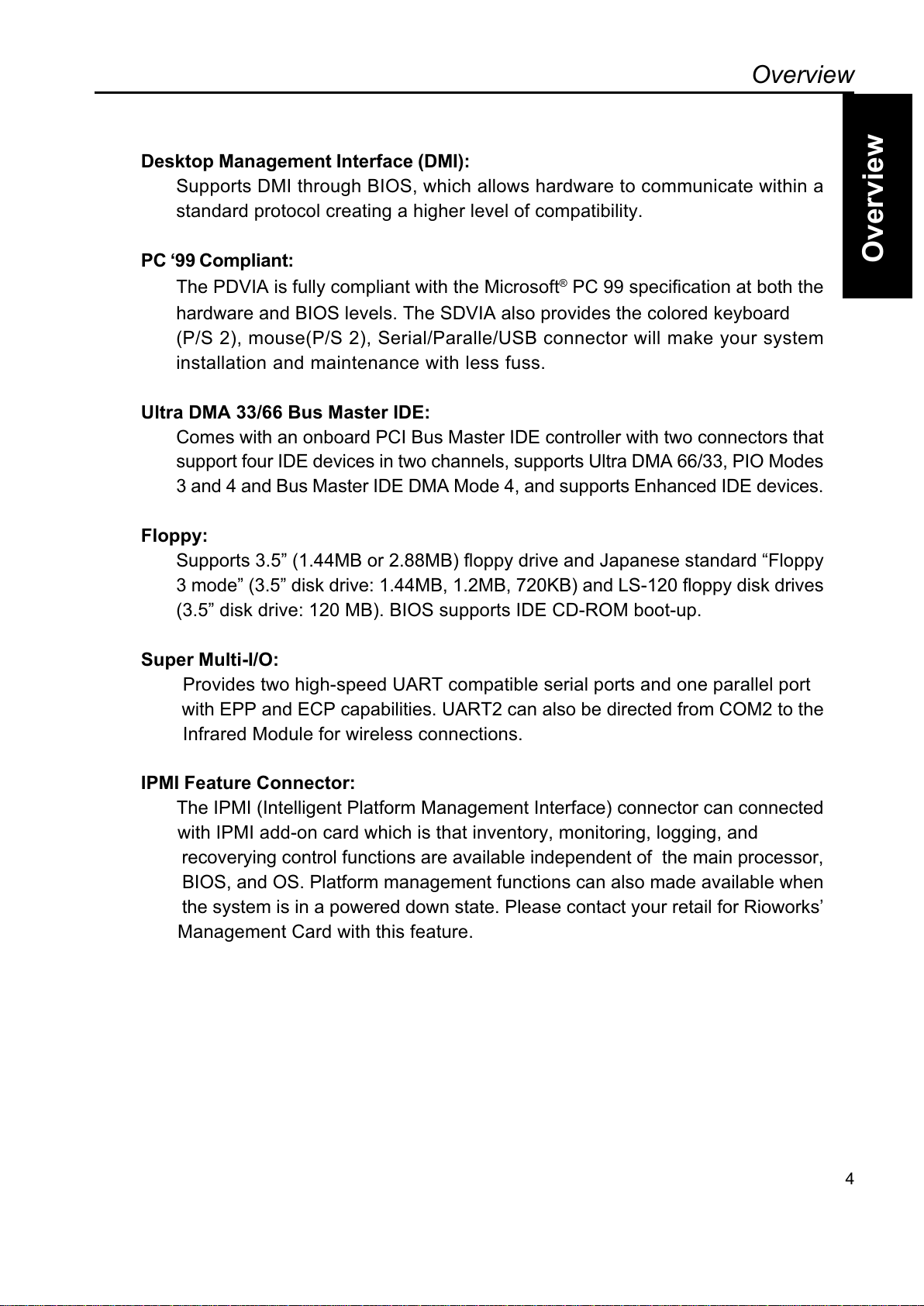
D sktop Manag m nt Int rfac (DMI):
Supports DMI through BIOS, which allows hardware to communicate within a
standard protocol creating a higher level of compatibility.
PC 99 Compliant:
The DVIA is fully compliant with the Microsoft® C 99 specification at both the
hardware and BIOS levels. The SDVIA also provides the colored keyboard
( /S 2), mouse( /S 2), Serial/ aralle/USB connector will make your system
installation and maintenance with less fuss.
Ultra DMA 33/66 Bus Mast r IDE:
Comes with an onboard CI Bus Master IDE controller with two connectors that
support four IDE devices in two channels, supports Ultra DMA 66/33, IO Modes
3 and 4 and Bus Master IDE DMA Mode 4, and supports Enhanced IDE devices.
Floppy:
Supports 3.5 (1.44MB or 2.88MB) floppy drive and Japanese standard Floppy
3 mode (3.5 disk drive: 1.44MB, 1.2MB, 720KB) and LS-120 floppy disk drives
(3.5 disk drive: 120 MB). BIOS supports IDE CD-ROM boot-up.
Sup r Multi-I/O:
rovides two high-speed UART compatible serial ports and one parallel port
with E and EC capabilities. UART2 can also be directed from COM2 to the
Infrared Module for wireless connections.
IPMI F atur Conn ctor:
The I MI (Intelligent latform Management Interface) connector can connected
with I MI add-on card which is that inventory, monitoring, logging, and
recoverying control functions are available independent of the main processor,
BIOS, and OS. latform management functions can also made available when
the system is in a powered down state. lease contact your retail for Rioworks
Management Card with this feature.
4
All manuals and user guides at all-guides.com
Overview
Overview
Getting Help
If a problem arises with yours system during installation or OS operating, you should
Ask your dealer for help first as your system has most likely configured by them. They
always have the best idea and quick response for your symptoms. If your dealer is
near to your locations, you should bring your system to them to have it quickly serviced
instead of attempting to solve the problem by yourself. Beside these, RIOWORKS
also provide some helpful resource to help you.
1. Select RIOWORKSTM website at www.rioworks.com and navigate to the SDVIA
product page that contains links to product updates such as Jumper settings,
BIOS updates, or Manual releases.
2. FAQ sections are often helpful since other users questions are often your own.
3. lease filling the system configuration form which in the RIOWORKS SETU
KIT CD-ROM and e-mail us at: [email protected] and we will try to answer
your questions within 24 hours.
5
All manuals and user guides at all-guides.com
Overview
Overview
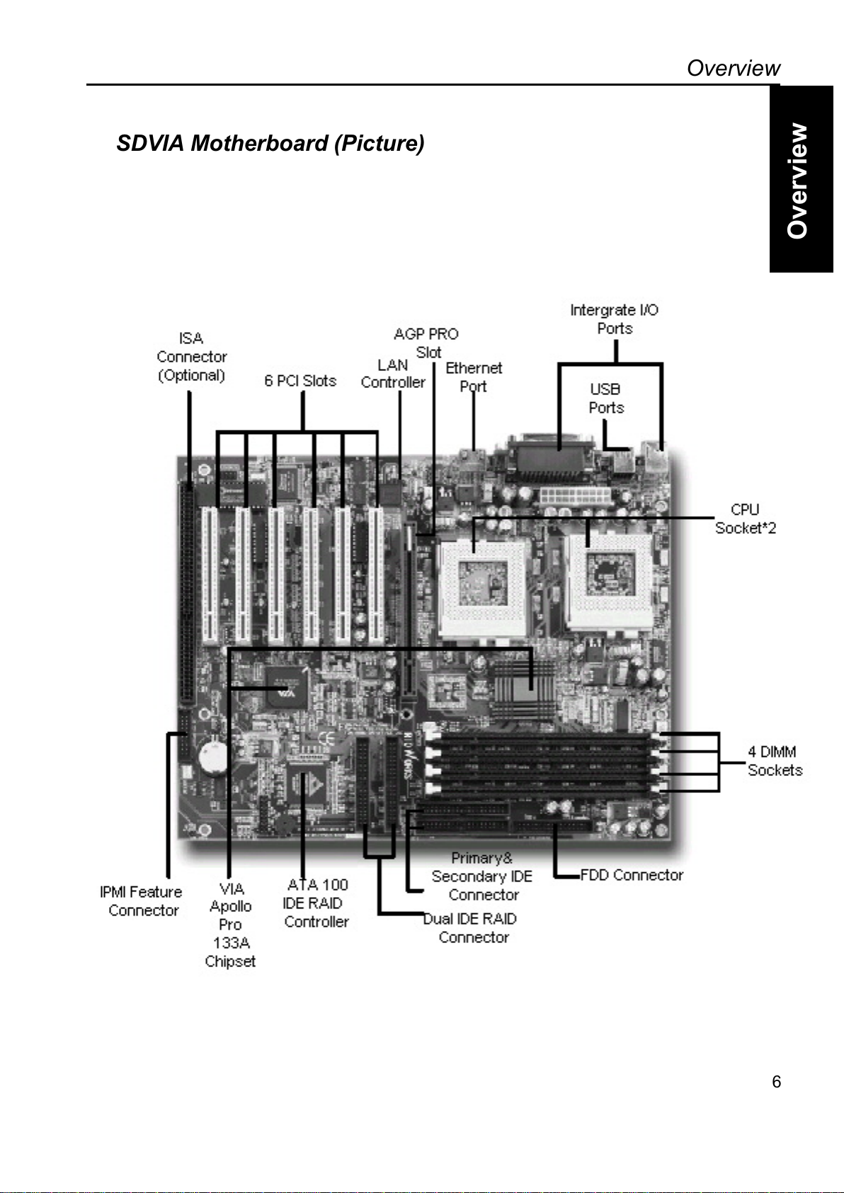
SDVIA Motherboard (Picture)
6
All manuals and user guides at all-guides.com
Overview
Overview
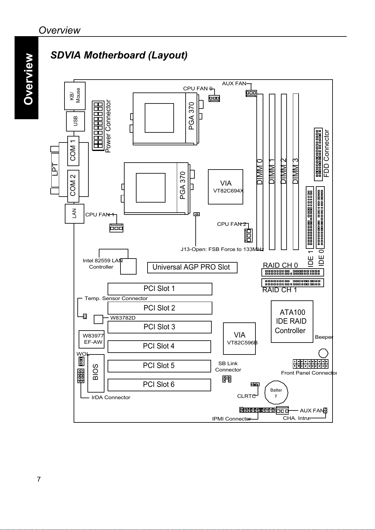
SDVIA Motherboard (Layout)
7
PCI Slot 2
PCI Slot 3
PCI Slot 1
DIMM 1
DIMM 2
VIA
VT82C694X
KB/
Mouse
BIOS
Universal AGP PRO Slot
COM 2 COM 1
LPT
USB
PCI Slot 4
DIMM 3
VIA
VT82C596B
W83977
EF-AW
DIMM 0
ATA100
IDE RAID
Controller
PCI Slot 5
PCI Slot 6
LAN
Power Connector
J13-Open: FSB Force to 133 Hz
CPU FAN 1
CPU FAN 2
FDD Connector
IDE 0
IDE 1
Intel 82559 LAN
Controller
W83782D
IrDA Connector
WOL
Beeper
Front Panel Connecto
r
SB Link
Connector
AUX FAN
CHA. Intru.
Temp. Sensor Connector
IP I Connector
PGA 370
PGA 370
AUX FAN
CPU FAN 0
*=JJAH
O
CLRTC
RAID CH 0
RAID CH 1
All manuals and user guides at all-guides.com
Overview
Overview
8
Note
If you are using a single processor on the DVIA M/B, please insert the C U in the C U
slot #0.
All manuals and user guides at all-guides.com
all-guides.com
Hardware Installation
Overview
Hardwar Installation
1-1
+D=FJAH
Hardware Installation
This chapter explains in detail the installation of the DVIA with the processor and
other hardware connected to your system.
Installation Procedures
Installation is broken up into six major parts.
Step 1: Jumper setting
Step 2: Install memory (DIMM modules)
Step 3: Install C U
Step 4: Attach cables to connectors
Step 5: Install expansion cards
Step 6: ower your computer
Warning
This motherboard contains sensitive electronic components that can be easil
y
damaged by static electricity. Follow the instructions carefully to ensure correc
t
installation and to avoid static damage.
All manuals and user guides at all-guides.com
Hardware Installation
Overview
Hardwar Installation
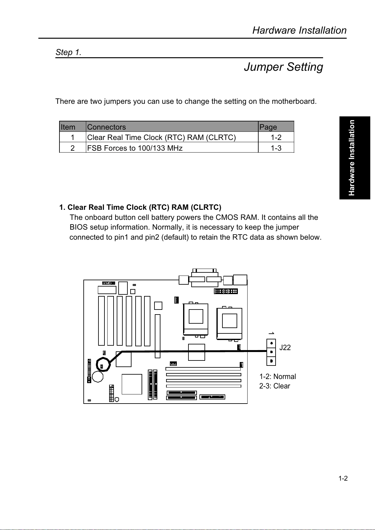
Step 1.
Jumper Setting
There are two jumpers you can use to change the setting on the motherboard.
Item Connectors age
1 Clear Real Time Clock (RTC) RAM (CLRTC) 1-2
2 FSB Forces to 100/133 MHz 1-3
1. Cl ar R al Tim Clock (RTC) RAM (CLRTC)
The onboard button cell battery powers the CMOS RAM. It contains all the
BIOS setup information. Normally, it is necessary to keep the jumper
connected to pin1 and pin2 (default) to retain the RTC data as shown below.
1-2
1
1 2: Normal
2 3: Clear
J22
All manuals and user guides at all-guides.com

Hardware Installation
Overview
Hardwar Installation
Note
Should you want to clear the RTC data:
(1) Turn off your computer
(2) Short pin2 and pin3 with jumper for two seconds
(3) Connect pin1 and pin2 with jumper
(4) Turn on your computer
(5) Hold down <Delete> during bootup and enter BIOS setup to re-enter user
preferences.
2. FSB Forc to 133 MHz (Jump r CN6)
This jumpers allow the user to force the FSB frequency of the C U to a specify
value. According to this value, a user can set a range of values in the selection
C U speed setting in the BIOS utility. ( lease also refer to
age 2-34). This is only for Overclocking purpose
CN6 D scription
Close System will detect the FSB frequency of the C U
automatically. (Default)
Open Force the 100MHz FSB frequency of the C U to
133MHz
1-3
CN6
Open: FSB force to 133 Hz
All manuals and user guides at all-guides.com
Hardware Installation
Overview
Hardwar Installation
1-4
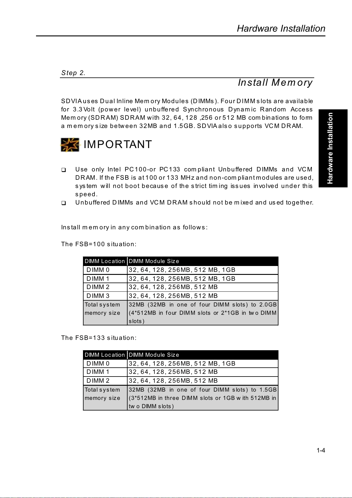
Step 2.
Install Mem ory
SDVIA uses Dual Inline Memory Modules (DIMMs). Four DIMM slots are available
for 3.3Volt (power level) unbuffered Sync ronous Dynamic Random Access
Mem ory (SDRAM) SDRAM wit 32, 64, 128 ,256 or 512 MB com binations to form
a m em ory s ize be tw ee n 32 MB a nd 1 .5GB. SD VIA als o s u pports VCM DR AM.
IMPORTANT
!" Use only Intel PC100-or PC133 compliant Unbuffered DIMMs and VCM
D R AM. If t e FSB is at 1 00 o r 133 MH z and n on -com pliant m odules are u sed,
system will not boot because of t e strict tim ing issues involved under t is
speed.
!" Unbuffered DIMMs and VCM DRAM s ould not be mixed and used toget er.
Install memory in any combination as follows:
T e FSB=100 situation:
DIMM Location DIMM Module Siz e
DIMM 0 32, 64, 128, 256MB, 512 MB, 1GB
DIMM 1 32, 64, 128, 256MB, 512 MB, 1GB
DIMM 2 32, 64, 128, 256MB, 512 MB
DIMM 3 32, 64, 128, 256MB, 512 MB
Total system
memory size
32MB (32MB in one of four DIMM slots) to 2.0GB
( *512MB in four DIMM slots or 2*1GB in two DIMM
slots)
T e FSB=133 situation:
DIMM Location DIMM Module Siz e
DIMM 0 32, 64, 128, 256MB, 512 MB, 1GB
DIMM 1 32, 64, 128, 256MB, 512 MB
DIMM 2 32, 64, 128, 256MB, 512 MB
Total system
memory size
32MB (32MB in one of four DIMM slots) to 1.5GB
(3*512MB in three DIMM slots or 1GB w ith 512MB in
tw o DIMM slots)
All manuals and user guides at all-guides.com
Hardware Installation
Overview
Hardwar Installation
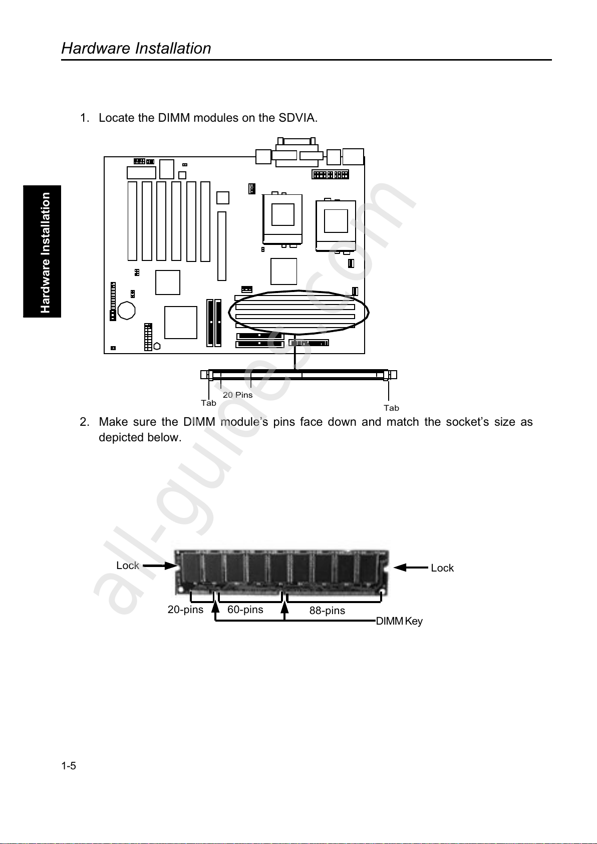
1. Locate the DIMM modules on the SDVIA.
2. Make sure the DIMM modules pins face down and match the sockets size as
depicted below.
1-5
Lock Lock
20-pins 60-pins 88-pins
DIMM Key
20 Pins
Tab
Tab
All manuals and user guides at all-guides.com
all-guides.com

Hardware Installation
Overview
Hardwar Installation
5. Insert the module straight down to the DIMM slot with both hands and press down
firm ly until the DIMM m odule is securely in place. (The tabs of the slot will close-up
to hold the DIMM in place when the DIMM touches the slots bottom .)
. Repeat step1 to step 3 to add additional DIMM m odules.
1-6
All manuals and user guides at all-guides.com

Hardware Installation
Overview
Hardwar Installation
Step 3
Install CPU
PDVIA provides one slot and one retention mechanism for Intel® 533~1G+ MHz
Pe nti m III pro ce s s or.
1. Lift th e le ver of C PU s ocket b efore ins tallin g th e C PU as de p icted in the fig re
below.
2. Loca te th e C PU in th e s ocket.
1-7
in One
All manuals and user guides at all-guides.com
Hardware Installation
Overview
Hardwar Installation
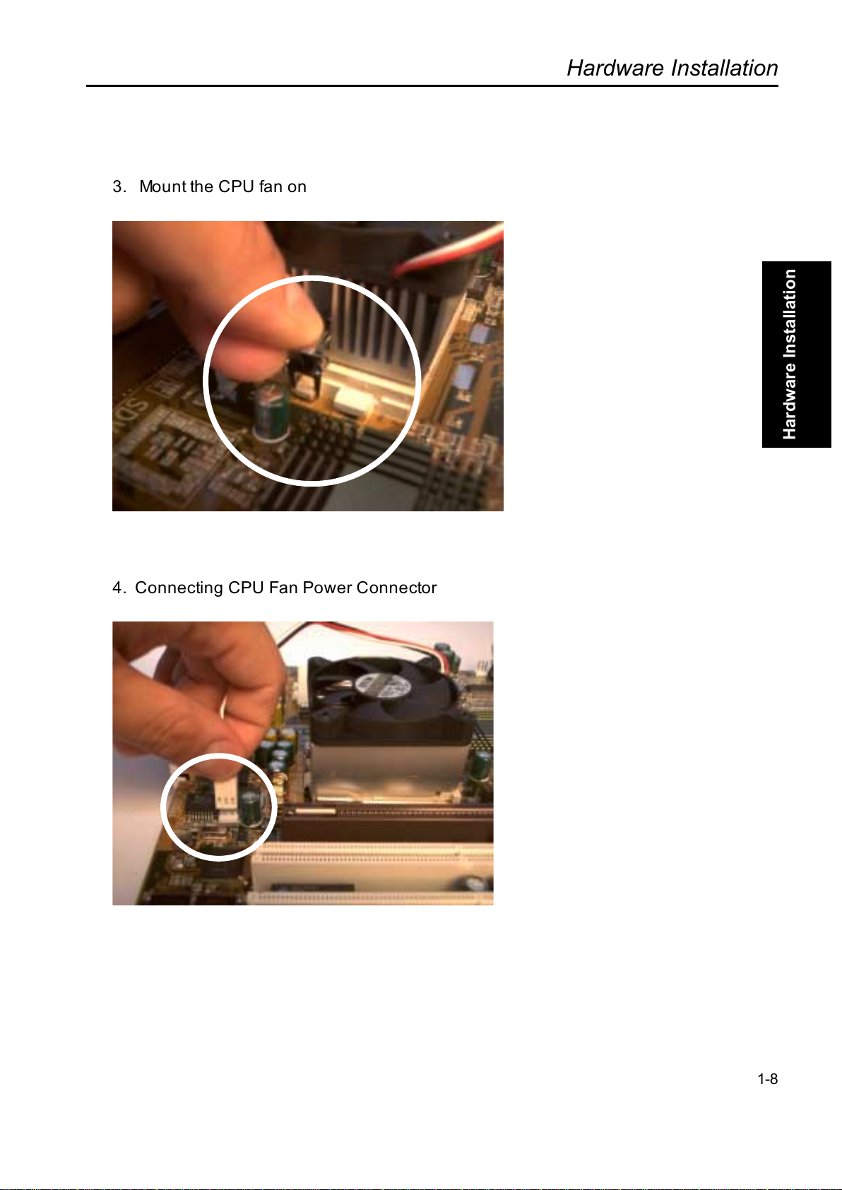
3. Mount the CPU fan on
4. Connecting CPU Fan Power Connector
1-8
All manuals and user guides at all-guides.com
Hardware Installation
Overview
Hardwar Installation
1-9
(This age Intentionally Left Blank for Notes)
All manuals and user guides at all-guides.com
Other manuals for SDVIA
2
Other Rioworks Motherboard manuals


