Rioworks PURCA User manual

PURCA
User’s Guide

The information in this document is subject to change without notice
Arima Computer Corp. makes no warranty of any kind with regard to this
material, including, but not limited to, the implied warranties of merchantability
and fitness for a particular purpose.
Arima Computer Corp. shall not be liable for errors contained herein or for
incidental or consequential damages in connection with the furnishing,
performance, or use of this material.
ArimaComputerCorp.assumesnoresponsibilityfortheuseorreliabilityofits
software on equipment that is not furnished by Arima Computer Corp.
This document contains proprietary information that is protected by copyright.
All rights are reserved. No part of this publication may be reproduced,
transcribed, stored in a retrieval system, translated into any language or
computer language, or transmitted in any form whatsoever without the prior
written consent of Arima Computer Corp.
Copyright?2002by Arima Computer Corp.All rights reserved.
RIOWORKSTM is the trademark of Arima Computer Corp.
Other products and companiesreferred toherein the trademarks or registered
trademarks of their respective companies or mark holders.
Printed in Taiwan
Revision Version: 1.00
Release Date: July2002

Contents
Overview……………………….…………………………………………..iv
Unpacking……………………………………………………………..…..iv
Features Highlight…………………………………………………….…..v
About This User Guide…………………………………………………..viii
Getting Help…………………………………………………………...…..ix
PURCA Motherboard (Picture) ……………………………………..…...x
PURCA Motherboard (Layout) ……………………………………..…...xi
CHAPTER 1:Hardware Installation…………………..………….1
Step 1:Jumper Setting………………………………………………....1-1
Step 2:Install memory…………………………………………….…..1-3
Step 3:Install CPU………………………………………………….....1-6
Step 4:Attach Cable to Connectors …………………………….......1-8
1.ATX Power Supply…………………………….………….1-10
2.Floppy Disk Drive Connector………………………….....1-10
3.Primary / Secondary IDE Connectors…………………...1-11
4.Primary / Secondary IDE RAID Connectors…………....1-12
5.Reset Switch Header……………………………………..1-13
6.SCSI Hard disk Activity LED Header…………………...1-13
7.Hard Disk Activity LED Header………………….……....1-13
8.SPEAKER Header…………………………….…………. 1-14
9.ATX power switch/Soft Power Header…………………..1-14
10.System Power LED Header…………………….…….... 1-14
11.CPU and Aux Fan connectors………………….….…... 1-14
12.Wake-On-LAN Port…………………………………....... 1-15
13.PS/2 Mouse Port…………………………….…………...1-16
14.PS/2 Keyboard Port………………………….………......1-16
15.USB (Universal Serial Bus) Ports………….…………...1-16
16.Parallel Port………………………………….……….......1-17
17.Onboard LAN Connectors……………………………... 1-17

18.USB Header………………………………………..….... 1-17
19.Serial Port COM1 Port…………………………….….…1-18
20.Chassis Intrusion Sensor Connector…………………..1-18
21.Thermal Header…………………………….…………... 1-18
22.BMC COM Port……………………………….…………..1-18
Step 5:Install Expansion Cards……………………………………..1-19
Step 6:Powering on Your Computer………………….………..…..1-20
CHAPTER 2:BIOS SETUP…………………….………………....2-1
Starting BIOS Setup………………………………………………….…2-1
Using Setup……………………………………………………….…..…2-2
In Case of Problems……………………………………………….……2-4
Section 1:Main Menu………………………….………………………2-5
The Menu Bar………………………………………………2-6
The Legend Bar……………………...……………….……2-7
The Field Help Window……………………………………2-8
Main Menu Selections…………………………………..…2-9
Master and Slave Sub-Menus…………………………….2-9
Section 2:Advanced Menu…………………………………………..2-13
Advanced Chipset Control…………………………....…2-14
Advanced Processor Options……………………..….…2-15
Cache Memory…………...…………………………....…2-15
I/O Device Configuration Menu……………………....…2-16
Section 3:Security Menu………………………………………….…2-19
Section 4:Power Menu………………………………………………2-21
Section 5:Boot Menu…………………………………………………2-23
Section 6:Exit Menu……………………………………………….…2-26
Saving Values………………………….…..……….……..2-26
Exit Discarding Changes……………………………...….2-27
Load Setup Defaults……………………………..…….…2-27
Discard Changes……………………………………….…2-27
Save Changes………………………………………….....2-28

CHAPTER 3.1:BIOS BOOT UTILITY………………….…...3-1
Phoenix QuietBoot……………………………………………….……..3-1
Phoenix MultiBoot…………………………….……………………......3-2
CHAPTER 3.2:BIOS FLASH UPGRADE UTILITY………...3-4
Installation……………………………………………………………....3-4
Executing Phoenix Phlash16.exe program………………………….…....3-4
Appendix A: Troubleshooting……………………...…..4-1
Appendix B: Symptom Report Form……………..…...4-5

Overview
Thank you for choosing RIOWORKSTM PURCA high performance
motherboard. The PURCAsupport Single Intel Socket-604 Xeon (Prestonia)
at 400 MHz Front Side Bus (FSB) , based on Socket-604 motherboard (M/B)
and the ATX form factor featuring the ServerWorks chipset. As the latest
ServerWorks chipset is built in the M/B. In the memory support, PURCAfully
Four DIMMslots support up to4GB PC2100 memory with ECC function. One
more advantage is the PURCAprovides dualPromise (PDC20271) ATA-133
IDE RAID channels to increase I/O transformation to maximum 400MB/sec
(100MB/sec per IDE channel)
Flexibility and expandability are always concerned by RIOWORKSTM, PURCA
contains3PCI32slots?1PCI64and2PCI-Xslots fornumerousadd-oncards.
Otherfeatures such asDual Broadcom 5702 (32bit/ 66MHz) Gigabit Ethernet
controllerswill provide high system capabilities that meet a wide range of
demanding Sever applications.
Unpacking
Remove all items from the box and make sure you have thesefollowing items:
If you discover damaged or missing items, please contact your retailer.
?? One RIOWORKS PURCAmotherboard
?? One 80-wireATA-66 ribbon cable
?? One 40-pinATA-33 ribbon cable
?? One floppy ribbon cable
?? One bag of spare jumpers
?? One PURCAuser’s guide
?? One CD containing drivers and utilities
?? One OnboardRAID & LAN User’s Guide
?? IDE RAID driver disk(s)
Ove
rview
iv

Features Highlight
CPU
?? SingleIntelSocket-604Xeon(Prestonia)CPUat
400 MHz Front Side Bus (FSB)
?? Support 2.0+ GHz
?? Designed for Socket-604 technology.
Chipset
?? PURCA uses the latest ServerWorks Chipset
?? North Bridge:GC-SL
?? South Bridge:CSB5
?? I/O Bridge:CIOB-X2
?? Because the powerful features of its
components, it can fully support 2 PCI-X slots
and Four DIMM slots supports up to 4GB
PC2100 DDR DIMM Module with ECC function
support.
System
Memory
Support
?? Registered DDR DIMM Module Support Only
?? Four DIMM slots support up to 4GB PC1600
memory with ECC function
Onboard IDE
RAID
Controllers
?? Promise (PDC20271) ATA-133 IDE RAID
controller.
?? Support RAID level 0 / 1 /10
?? ATA/133 Compatible
Onboard LAN
Controllers
?? Dual Broadcom 5702 (32bit/ 66MHz) Gigabit
Ethernet controllers
Onboard VGA
Controller
?? ATI RageXL video controller with 8MB memory.
Overview
v

Onboard IDE
RAID
Controllers
?? Use Promise (PDC20271) ATA-133 IDE RAID
controller, and up to four drivers.
?? Support RAIDlevel 0 /1/10
?? ATA/133 Compatible
IDE Controllers
?? Onboard PCI Bus Master IDE controller provides
two IDE connectors. And each connector
supportstwo IDE devices.
?? Support UltraDMAmode 5 (ATA-100), Ultra DMA
mode 4 (ATA-66) Ultra DMA33, PIO Mode 3 and
4 and Bus Master IDE DMA Mode 4, and
supports Enhanced IDE devices.
Expansion
Slots
?? Contain 3PCI-32 slots ?1 PCI-64 slot and 2
PCI-X slots.
Super Multi-I/O
?? NS super I/O
?? 1 Floppy Connector
?? 1+1 serial ports with UART 16550
?? One Parallel port with ECP/EPP support
?? Dual ICMB Connectors
?? Dual Onboard USB Connectors 2 USB headers
?? PS/2 mouse and keyboard connectors with
Wake-Up function.
Dimension
?? Extended ATX form factor-12"x10.5"
Wake-On-LAN
?? Support Wake-On-LAN activity with onboard
NIC /internal network card that contain WOL
connector when enable the function” Wake Up
on LAN” in the power management of BIOS
Setup Utility.
Overview
vi

BIOS Support
?? PhoenixBIOS on 4MB flash
?? Supports IDE CD-ROM boot-up.
?? Legacy USB support
?? Jumper-less setting for Vcore and CPU host bus
frequency setting table
?? MO, DVD, CD-ROM support
Enhanced
ACPI
?? Fully implements the ACPI standard for
Windows 98/NT4.0/2000 compatibility.
Desktop
Management
Interface (DMI)
?? Support DMI through BIOS, which allows
hardware to communicate within a standard
protocol creating a higher level of compatibility.
Hardware
Monitoring
?? Winbond 83910F BMC (Base-board
Management Controller) onboard
?? IPMI compliance feature connector
?? RIOWORKS SmartWatch™ Software.
PC99
Compliant
?? PURCA is fully compliant with the Microsoft
PC99 specification at both the hardware and
BIOS levels.
VRM Support
?? Support VRM 9.1 specification.
OS Support
?? Windows 2000
?? Linux Red Hat7.x
vii
Overview

About This User Guide
This manual explains how to build up your system with PURCAin detail.
Please follow the procedures of this User Manual carefully and pay special
attention totheseicons.
IMPORTANT
This icon informs you for particularly important
details regarding the setup or maintenance of
your system. While we point out the most vital
paragraphs in a chapter, you should always
read every word carefully. Failing to do so can
cause exasperation.
WARNING
This icon alerted you for potential dangers
during setting up your system with PURCA.
These warnings should not be regarded as the
whole of your safety regimen. Never forget that
computer are electronic devices and are
capable of delivering a shock. Prevent damage
to yourself and to your board: always ensure
thatyoursystemisturnedoffandunpluggedthe
power cords whenever you are working with
it ,and that you are equipped
NOTE
This icon alerted you for noticeduringsettingup
your system. It provides you can useful alert
during setting up a new system.
TIP
This icon will show you how to configure your
system with PURCA in aneasy and simple
ways. This icon always provides some useful
description to help you configure your system.
Overview
viii

Getting Help
If a problem arises with your system during installation or OS operating, you
should ask your dealer for help first as your system has most likely be
configured by them. They always have the best idea and quick response for
your symptoms. If your dealer is near to your locations, you should bring your
system to them to have it quickly serviced instead of attempting to solve the
problem by yourself. Besides these, RIOWORKS also providessome helpful
resources to help you.
1. Select RIOWORKS TM ‘s website at www.rioworks.com and navigate to
this product page which contain links to product updates such as Jumper
settings or BIOS updates.
2. FAQsectionsonRIOWORKSWebsiteareoftenhelpfulsinceotheruser’s
questions are often your own.
3. Emailusat:[email protected] andwewilltrytoansweryourquestions
ease fill in the symptom report form in order to let our engineers solve
your problemquickly.
Overview
ix
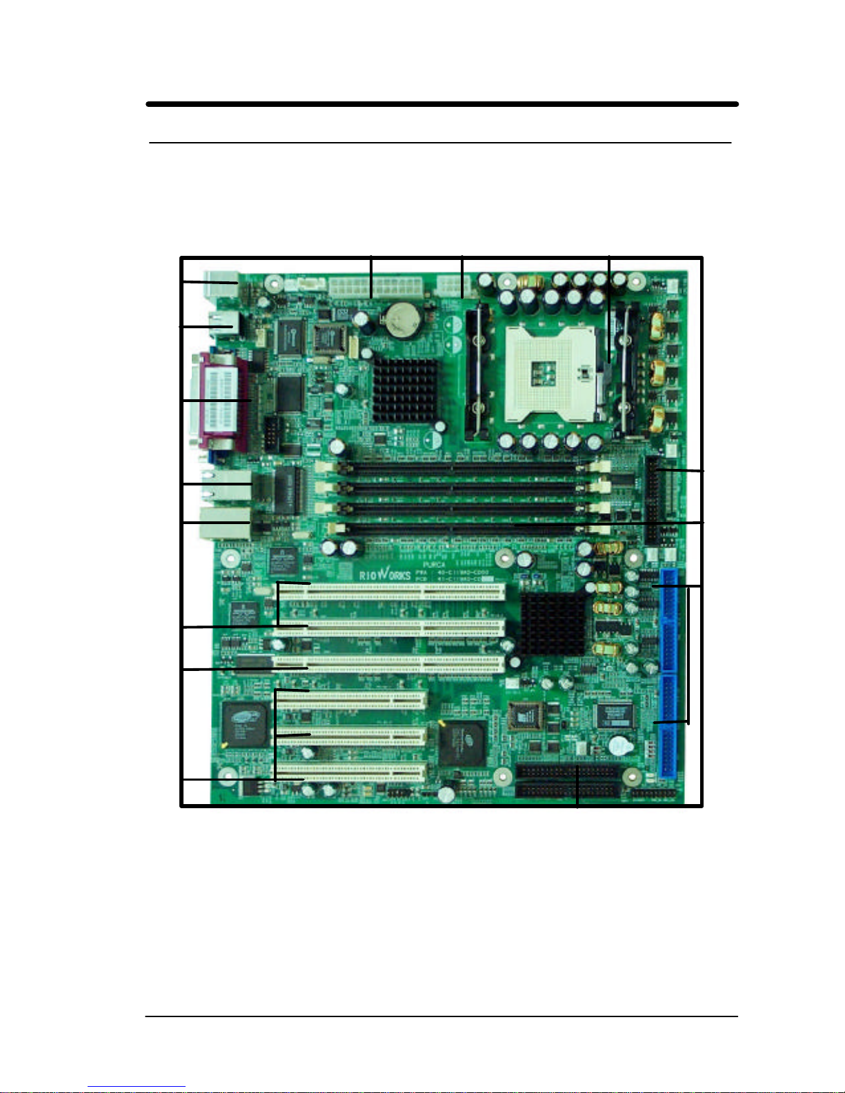
PURCA Motherboard (Picture)
ATX Power Connector CPU Heatsink Power ConnectorIntel Socket 604 CPU
4 DDR
DIMM
Sockets
Primary/
Secondary
IDE Connectors
IDE_RAID
C
o
nnectors
PS/2 ports
USB Ports
COM1 Port
VGA Port
Parallel Port
Dual LAN
Ports
Dual ICMB
Ports
3PCI-
32
Slot
Floppy
Device
1PCI-
64
Slots
2PCI-X
Slots
Overview
x

PURCA Motherboard (Layout)
xi
Overview

Chapter 1 Hardware Installation
In this chapter,the installation of the PURCA with the processor and other
hardware connected to your system will be explainedin detail.
Installation Procedures
Installation procedures will be brokendown to six major parts.
Step 1:Jumper setting
Step 2: Install memory (Registered DDR DIMM Module)
Step 3: Install Intel Socket-604 Xeon (Prestonia) CPU
Step 4: Attach cables to connectors
Step 5: Install expansion cards
Step 6: Power connection
Warning
This motherboardcontains sensitive electronic components that can be
easily damaged by static electricity. Follow the instructions carefully to
ensure correct installation and to avoid static damage.
Hardware Installation
1

Hardware Installation
Step 1. Jumper Setting
There are two jumpersyou can use to change the setting on themotherboard.
1. Clear Real Time Clock (RTC) RAM
The onboard button cell battery powers the CMOS RAM. It contains all the
BIOS setup information. Normally, it is necessary to keep the jumper
connected to pin1and pin2(Default) to retain the RTC data as shown below.
Note
Should you want to clear the RTC data:
(1) Soft off your computer
(2) Short pin2and pin3with jumper for few seconds
(3) Connect pin1and pin2with jumper again.
(4) Turn on your computer by pressing the power-on button from front-panel.
1
-
1
1
2
3
1?2 Normal
2?3 Clear CMOS
PURCA Clear CMOS Header

Hardware Installation
(5) Hold down <Delete> during bootup andselect <Load Optimal Defaults>or
<Load Failsafe Defaults> option in the selection <Exit>. Then re-enter
BIOS setup to re-enter user preferences.
1
-
2

Hardware Installation
Step 2 Install Memory
PURCA uses 184-pin Double Data Rate (DDR) Inline Memory Modules
(DIMM). Four DIMM slots are available for 2.5 Volts (power level),
PC2100,Registered DDR DRAM Module with 1MB, 2MB, 4MB, 8MB, 16MB,
32MB, 64MB, 128MB, 256MB, 512MB and 1GB combinations. Memory size
can support up to 4GB.
IMPORTANT
?? PC2100 RegisteredDDR DRAM Module Support Only.
?? Supports 4 banks up to 4GB DDR DIMM Modules for Registered
DDR modules.
1
-
3

Hardware Installation
Memory Installation Procedures
1. Locate theDIMM modules on thePURCA
2. Make sure theDIMM module’s pins facing down and match the slot’s size
as depicted below :
1
-
4
PURCA Memory Module
104 Pin80 Pin
DDR RAM
(Double Date Rate RAM)
104 pins 80 pins

Hardware Installation
3. Insert the module down to the DIMM slot in with both hands and press
down firmly until the DIMM module is securely in place.(The tabs of the
slot will close-up to hold the DIMM in place when the DIMM touches the
socket’s bottom.)
4. Repeat step1 to step 3 to add additional DIMM modules.
WARNING
PC2100 Registered DDR DRAM Module Support Only.
1
-
5
TAB
TAB

Hardware Installation
Step 3Install CPU
PURCA supportsSingle Socket604 Xeon (Prestonia) at 400 MHz Front Side
Bus (FSB)
CPU Installation Procedures
1. Liftupthesocketleverandcarefullyplacethesocket604 Xeon(Prestonia)
CPU with the correct orientation as the figures are shown below
2. Mount the CPU heatsink with proper exproxy as shown below.
1
2
3
4
1
-
6
Table of contents
Other Rioworks Motherboard manuals


