manuals.online logo
Brands
  1. Home
  2. •
  3. Brands
  4. •
  5. Ripmax
  6. •
  7. Toy
  8. •
  9. Ripmax Hellcat Slim User manual

Ripmax Hellcat Slim User manual

I
C’
2
cc
C—
S
HELLCAT
SLIM
INSTRUCTION
MANUAL
Introduction:
Thank
you
for
buying
the
Ripmax
Hellcat
Slim and
welcome
to
the
instruction
manual.
The
Hellcat
Slim
is
a
cartoon
profile
scale
model
of
the
world famous
Grumman
Hellcat
Second
World
War
naval
fighter.
The
profile
fuselage
and
intentional deviations
from
scale
result
in
a
model
which
is
capable
of
manoeuvres
even
the full
size
aeroplane
could
not perform.
With
the
right
pilot
the
model
is
capable
of
all
normal aerobatic
manoeuvres
such
as
rolls,
loops,
spins,
etc,
as
well
as
hovering
(I/C only),
prolonged
knife
edge
flight,
etc.
For
ultimate
performance
a
computer
radio
is
not
needed,
the
model’s
capabilities
are
still
astounding
with
a
standard
radio.
With
reduced
movement
and
the
C.G.
moved
forward,
the
Hellcat
Slim
becomes
an
ideal
second
or
third
model
with
stable
yet aerobatic characteristics.
The
light
weight
of
the
Hellcat
Slim
gives
it
the
ability
to
fly
in
very
small
areas
as
the
landing
speed
can
be
so
low
that
the
model
does not have
a
landing
roll
at
all.
The
Hellcat
Slim
is
designed
for
electric
motors
of
540/600
size
along
with
a
gearbox
or
alternatively
IC.
engines
from
.15
to
.19
Cu
in
and
needs
a
minimum
of
4
channel radio.
Although
not
a
complete
beginners
model
it
is
suitable
as
an
advanced
trainer with restricted
control surface
movements.
Glues
and
finishing
materials:
Grip
thin
and
thick Cyanoacrylate
adhesive
Grip
5
minute
epoxy
Grip
PVA
or
Aliphatic
glue
Covering
materials
Please
be
aware
of
the
hazards
involved
in
the
use
of
cyanoacrylate
and
epoxy glues
and only
work
in
an
area
that
is
well
ventilated
and
has
good
lighting.
Before
beginning
construction
it
is
useful
to
go
through
the
kit,
plan
and
instructions
to
understand
the
building
sequence.
Radio
used
in
the
prototypes
was Futaba,
both
with
and
without
mixing facilities.
We
recommend
the
use
of
mini
size
servos
for
the
flying surfaces,
Ripmax
SD200
servos
were
used
on
all
the
prototypes.
Page
2
The
recommended
power
combination
for
the
standard electric
version
is,
M-DYD22802
Speed
600
motor
8.4v
11”
x
8”-12”
x
8”
wood
Propellor
M-1784.25
Graupner
Power
Gear
2.5:1
Gearbox recommended
O-7NRCI
700LT
Sanyo
8.4v
1700
mAh
battery
pack
P-SUNG-GS3O
Sung
Ji
4-10
cell
Bec
speed
controller
or
P-PRO-035
Protech
7-10
cell
Bee speed
controller
For
increased
performance
the
following motor
is
recommended,
M-K70671
Kyosho Magnetic
Monster
27
turn motor
For
increased
flight
times the
following
battery
pack
is
recommended,
O-7NRC2000LT
Sanyo
8.4v
2000 mAh
battery
pack
You
will
also
need
a
suitable
charger
for
the battery
pack.
For
the
I/C
version
we
recommend,
L-MDS-01700
MDS
17
with
Quiet
silencer
8”
X
4”
Propellor
recommended
L-RGA2026
60cc
(2oz)
thel
tank
Wing
construction:
1/
To
start
wing
construction,
select
from
1/4”
square
strips
the
two
hardest
pieces
to
become
the
main
spars
(part
20).
2/
Cut
the
ends
of
the
1/4”
square
wing
joiners
(part
25
)
as
per
the
plan before gluing
to
the
main
spars.
Do
this operation
against
a
straight
edge
to
ensure
a
straight
spar assembly
3/
Select
the
three
wing ribs
for
the wing
root
area
(parts
16).
At
this
stage
it
is
wise
to
make
a
hole
in
the
three
ribs
which make
up
the
centre
triple
rib
assembly
for
servo
leads
etc.
If
making
the electric
version
check
that
the
battery
pack
to
be
used
fits
snugly in
the precut
battery
supports
(
part
27/28
)
before
laminating them together
as
shown
on the plan.
Using
the
laminated
battery
support
as
a
template mark
and
cut
an
identical
hole
in
the
centre
rib assembly.
4/
Take
the
1/4”
square
T/E
(
part
47
)
and
sand
a
slight
angle
on
one face,
the
aim
is
to
allow
this
strip
to
match
up
to
the
rear
of
the ribs
once
it
is
glued
to
the
TIE
sheet
(part
15),
see
wing
section
drawing.
Glue the
TIE
and
T/E sheet
together
and
mark
the
position
of
all
the
wing
ribs
on
the
LIE
strip
and T/E
assembly.
5/
Pin
the
main spar
to
the
board
and
dryfit
all
the
ribs.
Offer
up and
support
the T/E
assembly
with
suitable
packing
ensuring
that
the
assembly
is
supported
level
and
will not
allow
the
wing
to
twist.
Page
3
6/
Align
the
ribs
on
the
TIE
assembly
and
spar
using
a
square
to
check
ribs
are
vertical,
7/
Assemble
the
centre section
triple
rib
from
3
pcs
of
part
16
then
glue
all
ribs
to
the
spar
and
TIE
using
thin
cyanoacrylate
or aliphatic
glue.
8/
Add the
LIE
(part
14)
top
main
spar
and the
front spar (part
24)
using
thin
cyano.
97
Add
gussets
(cut
from
scrap
)
to
TIE
to
tip
rib
joints.
When
glue
is
thy,
sand
the
top
of
the
TIE
snip
flush
with
the ribs and add
top
TIE
sheet
(
part
15).
10/
Glue
the
centre
section
sheet
(part
23
)
from
the
TIE
sheet
forward
over
the
LIE.
The
easiest
way
to
do
this
is
to
rim
a
bead
of
thick
cyano
along
the
rib tops,
spars
and
L/E and
carefully roll
the
sheet
down
starting
at the
TIE
sheet.
Ill
Add
cap
strips
(part
22)
from
TIE
sheet
to
the
front
of
the
LIE.
12/
Remove
panel
from
board,
turnover
and
pin down
to
board.
Add
bottom
front
spar,
cap strips
(parts
21/22)
and
centre
section
sheeting,
leaving
hatch
apertures
open.
13/
Add the
precut
wingtips
along
with
the
1/8”
gussets
and the
1/4”
square
tip
covering
supports.
14/
At
this
point
you
need
to
decide
whether
you
will
be
using
the
GIF
pushrods
supplied
or
closed
loop
controls
for
the
elevator
and
rudder.
If
using
an
I/C
engine
we
recommend
the
0/F
pushrods, when using electric power
the
lighter
weight
of
closed
ioop
controls
(
not
supplied)
will
help
minimize overall
weight.
If
you
have decided
to
use
closed
loop
controls
you
will
need
to
fit
small
aluminium
or
plastic leadout
tubes
into
the
TIE
as
shown
on
the
plans,
alternatively,
if
you are using
pushrods
you
will
need
to
cut
slots
in
the
top
wing surface
to
allow
for
the
pushrod
clevis
connection
to
the
servo
horns. Add the
1/32”
ply
(pan
49
)
servo
supports
to
the
underside
of
the
top
wing sheeting
having cut
horn slots
as
required.
15/
Cut
the
aileron
servo
aperture
in
the
centre
rib
assembly
to
suit
the
servo
being
used,
then
glue
the
1/32”
ply
aileron
servo mount
(part
52
)
to
one
side
of
the
centre
rib
assembly.
The
aileron
servo
can
then
be
servo
taped
to
the
ply.
16/
Sand
entire
wing
ready
for
covering
Page
4
Fuselage
construction:
1/
Before commencing
fuselage
construction check
the
width
of
the
gearbox
(
electric)
or
crankcase
of
the
engine
(I/C)
to
be
used
and
compare
to
the
plan.
Adjust
the
position
of
the
upper
motor
mount/engine
bearer
to
suit
and
trim
or
pack
the
fuselage
top
core
(part
1)
to
fit.
2/
Cover
the
plan
with
clear
film
(
solarfllm
backing
is
perfect),
pin
down
the
fuselage
bottom
cores
(part
2)
and
glue
the
spruce
longeron
(part
4)
and
lower
motor
mount
(part
10)
or
engine bearer
(
part
3
)
into
place.
3/
Glue upper
motor
mount/engine
bearer
and
fuselage
top
core
(
part
2
)
into place.
4/
Add
the
lower
3/8”
square
front
stringer
before
laminating
together
the
3
pcs
U/C
insert
(
part
5)
and
gluing
into
place.
5/
Using
stringers
(parts
7,8 &
9
)
assemble
the
remainder
of
the
fuselage
over
the plan.
6/
Once
the
glue
has set
gently
sand
the
fuselage
smooth
before gluing
the
1/32”
ply
fus
doubler
(part
6
)
to
the
front
fuselage,
weight
down
while
glue
dries
to
avoid
warping.
7/
The
lower
rear
part
of
the fuselage
can
now
be
sheeted
with
1/16”
sheet
(part
11).
This
is
unnecessary
with
the
electric version
but
adds
useful
rigidity
to
the
I/C
version.
shape
from
1/16”
sheet
(part
II)
the
rear
fuselage
sides.
Where
fitted
the
sheet should
butt
up
to
the
back
of
the
1/32”
ply doubler.
Remove
from the
board,
turn
over
and add
the
other
side
ply
doubler
and
balsa
rear
fuselage
side.
The
front
of
the 1/16”
sheeting
can
be
sanded down
to
blend
into
the
1/32”
ply
doubler.
8/
Carve
and sand
the
engine
failing
(part
50
)
to
shape
and glue
to
fuselage
side,
depending
on
the
gearbox/engine used
it
may
be
necessary
to
hollow
the
fairing
to
give
clearance
to
the
bottom
of
the
gearbox/crankcase.
9/
Bend tailskid
(
part
43
)
to
shape
and glue
and
bind
to
tailskid
mount
(part
13
)
which
should
be
trimmed
to
the
shape
shown
on
the
plan.
Glue
tailskid
assembly
into
place
10/
Sand the
fuselage
smooth
and
put
to
one
side
for
covering.
Page
5
Control
surface
construction:
1/
Build ailerons, tailpiane,
elevator,
fin
and
rudder
over
the
plan.
Ensure
a
good
fit
between
the
elevator
L/E and
the elevator
joiner
(part
42).
2/
Glue
the
fin
to
the
top
rear
fuselage
assy,
packing
the
fin
off
the
board
to
ensure
correct
positioning.
3/
Bevel
the
leading
edges
of
the
ailerons,
elevator
and
rudder
and
sand
ready
for
covering
Covering:
Recommended
covering
materials
are
Solarfilm,
Fibaflim
or
Litespan
which
are
light,
colourful,
flielproof,
easy
to
apply
and
resistant
to
puncturing.
For
competition
use
Fibafilm
or
Litespan
are
recommended
as
they
are
lighter
and add
stiffness
to
the structure.
It
is
recommended
that
Clearcoat
or
Balsaloc
is
used
on
all
ply
parts,
all
around
the
nose
and around the
wing/fuselage
and
tail/fuselage
joints.
Ensure
that
the
tailplane,
fins and
all
control
surfaces
do
not
warp
when shrinking
the
covering
material.
All
parts
can
be
covered
before
final
assembly.
If
using this
technique
ensure
that the
centre
of
the
wing
and
tailplane
where
they
are
glued
to
the
fuselage
are
left
uncovered.
The
cockpit
area
can
be
covered
in
a
contrasting
colour
or
can
be
painted.
Final
assembly:
1/
Slide
the
wing
into
position
in
the
fuselage
taking
every
effort
to
ensure
that
the wing
is
perfectly
centralised
and
that
it
is
fitted
at
90
degrees
to
the
fuselage
sides,
Also check
that
the
wing
is
not
tilted
in
relation
to
the
fuselage
sides.
A1/16”
thick
packer should
be
added
to
the area
of
the
centre
rib
assembly
whichhas
not yet
been sheeted.
Once
happy
glue the
wing
into
position
with
slow epoxy
or
PVA.
2/
Once
the
wing/fuselage
glue
joint
has
cured
repeat
the
assembly
procedure with
the
tailplane
3/
Drill
through
the
U/C insert
and
fuselage doublers
for
the
u’c
clamps.
Secure u/c
legs
with
screws
and
nuts
and
fit
wheels, securing
with collets supplied.
4/ Control
surfaces
should
be
attached with
the
hinges
supplied,
thin
cyano
should
be
used which
will
“wick”
in to
the
balsa
for
increased
strength.
5/
Add
control
horns
to
the
ailerons,
elevator
and
rudder.
Page
6
Electric
installation:
1/
Fit
the
elevator
and
rudder
servos
with
servo
tape
having
centralised
them
and fitted the
servo
horn
first,
it
is
helpful
to seal
the
surface
pf
the
ply
mounting
plates
with epoxy
or
cyano
before
attaching
the
tape.
If
using
closed
loop
controls
attach
the cables
before installing
the
servos,
both cables
exit
through
one
tube.
2/
Install the
receiver
and
speed
controller
to be
used
then
add
the
battery supports,
ensuring
that
you
leave
room
to
access
both units.
You
may
need
to
reposition
the
supports
compared
to
the
plan
position.
3/
Cut
away
the
bottom
of
the
fuselage
where
it
covers
the
battery
cutout
in
the centre
rib
assembly
and
check
that the battery
to
be
used
can
be
slid
into
position,
trim
rib
as
necessary.
The
battery
is
retained
by
two
elastic
bands.
4/
The
motor/gearbox
to
be
used
should
be
screwed
into
position.
If
using
the
recommended
Graupner
unit
add
1/8”
ply
or
liteply
spacers
between
the
fuselage
doubler
and
the
gearbox
to
space
the
gearbox
slightly
further
outboard.
Enaine
and
fuel
tank
installation:
1/
Fit
propellor
and
spinner
to
the
engine
and
position
the
engine
over the
bearers.
Mark
and
drill
bolt
holes
then
counter
drill the
balsa
engine fairing to
allow
the
engine
bolts,
fined
with washers,
to
sit
down
onto the
ply doublers.
2/
Ito
3
degrees
of
right sidethmst
can
be
used
depending
on
engine/propellor
combinations.
Use
plastic
moulded
thrust
plates
if
required
3/
Fit
fuel
tank
to
fuselage
side
behind
and
level
with
the
engine,
it
is
advisable
to
use
some foam
between
the
tank and
the
fuselage
side
to
avoid
foaming
of
the
fuel
due
to
vibration.
The
tank
is
retained
by
elastic bands
attached
to
cup
hooks
screwed
into
the
fuselage
side.
4/
For
the
I/C
version
the
rudder and
elevator pushrods
are
fibreglass rods
and
need
the
wire
pushrod
ends
binding
and
gluing
to
them
before
final
fitting.
N.B.
It
is
important
that the
plastic
pushrod
support brackets
are
drilled
and
fitted
onto the rods
before
both
wire
pushrod
ends
are
fitted
as
they
cannot
be
fitted
later.
5/
The
plastic
pushrod
support brackets
are
screwed
to
the
fuselage
sides
approximately
halfway
along the
length
of
the pushrod.
Make
sure
that
the
screws
are
located
so
they
screw
into
part
of
the
1/8”
x
3/8”
structure
and
put
a
drop
of
epoxy
or
slow
cyano
in
the
hole before
finally
tightening
the
screws.
6/
The
battery and
receiver
are
installed
in
the
left
wing
to
balance
the
lateral
weight
of
the
engine.
As
the
model
is
one
piece
it
is
sensible
to
fit
a
remote
charging
facility,
the
ones used
on the
prototypes
were
the
P-R4-ECH
remote
charging
sockets.
Page
7
I
Flying
instructions:
Before
flying
the
Hellcat
Slim
for
the
first
time
check
both
longitudinal
and
lateral balance.
The
C/G
should
be
90
mm
(
3
Y2”)
from
the
LIE
of
the wing.
Use
a
more
forward
position
for
first
flights
unless
you
are
an
experienced
pilot
of
this type
of
model.
For
the
ultimate
in
tight
loops
and
knife
edge
loops
the
C/G
can
be
moved back
ffirther
but
this
should
only
be
done
by
advanced
pilots.
Lateral balance
can
be
corrected
with
a
small
amount
of
lead on the
lefthand wingtip.
For
first
flights
set
control
movements
as
follows,
Ailerons
I”
each
way
at
root
TE
Elevator
1/2”
each
way
Rudder
I”
each
way
Please
note that
the
Hellcat
Slim
is
designed
to be
as
manoueverable
as
possible
and
is
not
designed
for
high
speed
diving
manoeuvres.
Full
power
can
used
during
aerobatics
and
in
level
flight
but
if
using
a
powerifil
engine
do
not
dive
the
model
steeply with
power
on.
Throttled
back
the
model
can
safely
be
dived
vertically.
All
normal
manoeuvres
can
be
performed with
the
Hellcat
Slim, loops,
rolls,
point
rolls,
slow
rolls,
spins
and
inverted
are
all
easy to
perform
without
taking
large
amounts
of
airspace.
Where the
model comes
into
its
own
is
the
more advanced
aerobatics
such
as
hovering,
fast
or
slow
knife
edge,
knife
edge
loops
etc.
Ensure
that
the
flight battery
pack
is
retained
securely
by
elastic bands
as
it
can
otherwise
break
free
through
the
hatches,
which
are
only
sprung
into
place
at
the
front.
PageS
RIPMAX
HELLzCAT
SLIM
Parts
list:
1/
Fuselage
top
core
3/8”
Precut
Balsa
1
21
Fuselage
bottom
core
3/8”
Precut
Balsa
2
3/
Engine
bearer
3/8
x
3/8”
x
6”
Hardwood
2
4/
Longeron
3/8
x
1/8”
x
30”
Spruce
1
5/
U/c
insert
1/8”
Precut Liteply
3
6/
Fuselage
doubler
1/32”
Precut
Ply
2
7/
Stringer
3/8”
x
1/4”
x
18”
Balsa
5
8/
Stringer
3/811
x
1/4”
x
24”
Balsa
1
9/
Stringer
3/8”
x
1/8”
x
18”
Balsa
4
10/
Stringer
3/8”
x
3/8”
x
18”
Balsa
2
11/
Fuselage
side
1/16”
x
3”
x
24”
Balsa
2
12/
cheek
cowl
1/2”
x2
3/4”
x
6”
Balsa
1
13/
Tafiskid
mount
1/8”
x
1
3/4”
x
1”
Ply
14/
Wing
LIE
1/4”
x
1/4”
x
36”
Balsa
I
15/
Wing
TIE
sheet
1/16”
x
1”
x
36”
Balsa
2
16/
Wing rib
(WI)
3/16”
Precut
Balsa
3
17/
Wing
rib
(W2)
1/16”
Precut
Balsa
2
18/
Wing
rib
(W3)
1/16”
Precut
Balsa
6
19/
Wing
rib
(W4)
3/16”
Precut
Balsa
2
20/
Main
spar
1/4”
x
1/4”
x
36”
Balsa
2
21/
Cap
strip
1/16”x
1/2”x
18”
Balsa
22/
Cap
strip
1/16” X
1/4”
X36”
Balsa
6
23/
Centre section
sheeting
1/16”
x
3”
x
18”
Balsa
3
24/
Front
spar
1/8”
x
1/4”
x
36”
Balsa
2
25/
Spar
doubler
1/4”
x
1/4”
x
18”
Balsa
2
26/
Hatch
1/64
x
6”
x
8”
Ply
27/
Battery
support
centre
1/8”
Liteply
2
28/
Battery
support
sides
1/64”
Precut
Ply
4
29/
Centre sheet support
1/8”
x
1/4”
x
18”
Balsa
30/
Wingtips
1/8”
Precut
Balsa
2
31/
Aileron
frame
1/4”
x
3/8”
x
24”
Balsa
2
32/
Aileron frame
3/16”
x
3/16”
x
18”
Balsa
2
33/
Aileron frame
1/4”
x
1/8”
x
24”
Balsa
3
34/
Fin/Rudder
frame
3/16”
x
3/16”
x
18”
Balsa
1
35/
Fin/Rudder
frame
3/16”
x
3/8”
x
24”
Balsa
1
36/
Fin/Rudder
frame
3/16
x
1/8”
x
18”
Balsa
3
37/
Tailpiane
centre
3/16”
x
1”
x
2
1/2”
Balsa
1
38/
Tailpiane
frame
3/16”
x
3/16”
x
18”
Balsa
2
Page
9
39/
Tailpiane
frame
3/16”
x
1/8”
x
18”
Balsa
3
40/
Tailplane
frame
3/16”
x
3/8”
x
18”
Balsa
2
41/
Tailplane
&
elevator
tips
3/16”
Precut
Balsa
4
42/
Elevator
joiner
3/16”
x
3/8”
x
6”
Spruce
43/
Tailskid
14g
piano
wire
1
44/
U/C
clamp
8
SWG
moulded
4
45/
U/C
leg
Prebent
8
SWO piano
wire
2
46/
U/C
screws/nuts
M3
x
25
4
47/
Wing T/E
1/4”
x
1/4”
x
36”
Balsa
1
48/
Rudder
tip
3/16”
Precut Balsa
1
49/
Servo
support
1/32”
x
4”
x
3”
Ply
50/
G/F
pushrods
4mm
x
700mm
1
51/
Tip
gusset material
1/8”
x
3”
x
4”
Balsa
52/
Aileron
servo
mount
1/32
x
3”
x
6”
Ply
1
Other
parts:
Wheels
2.5”
2
Collets
8g
2
Horns
Moulded
4
Hinges
13
Pushrod
guides
Moulded
2
devises
5
Swing
keepers
5
Pushrods 2mm
threaded
4
Decals
1
Throttle
pushrod
16g
Clevis
adapter
1
Page
10

Other Ripmax Toy manuals

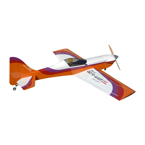
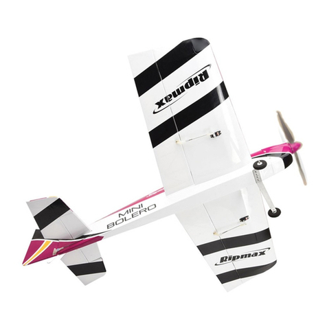
Ripmax MINI BOLERO User manual

Ripmax

Ripmax MINI BOLERO User manual

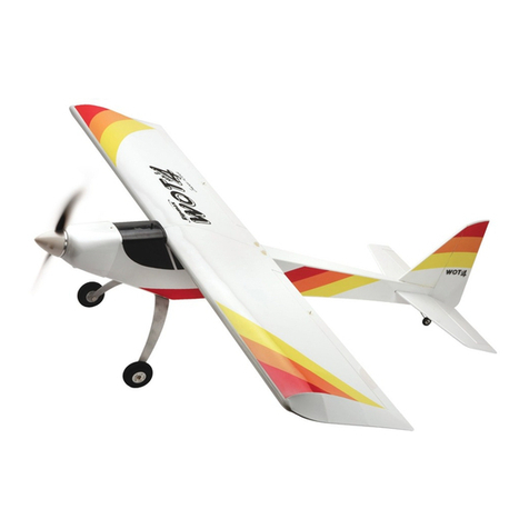
Ripmax Mini Wot4 User manual

Ripmax

Ripmax Mini Wot4 User manual

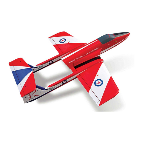
Ripmax Bullet User manual

Ripmax

Ripmax Bullet User manual

Ripmax BOLERO A-ARTF6720CS User manual

Ripmax

Ripmax BOLERO A-ARTF6720CS User manual

Ripmax Wots Wot FOAM-E User manual

Ripmax

Ripmax Wots Wot FOAM-E User manual

Ripmax Wot4 EP/GP User manual

Ripmax

Ripmax Wot4 EP/GP User manual

Ripmax Trainer 40 User manual

Ripmax

Ripmax Trainer 40 User manual

Ripmax Dagger User manual

Ripmax

Ripmax Dagger User manual

Ripmax J!VE Fun Fly User manual

Ripmax

Ripmax J!VE Fun Fly User manual

Ripmax SU KHOI31 Owner's manual

Ripmax

Ripmax SU KHOI31 Owner's manual

Ripmax Sky Spy A-ARTF68713 User manual

Ripmax

Ripmax Sky Spy A-ARTF68713 User manual

Ripmax Chris Foss WOT Trainer A-CF001A User manual

Ripmax

Ripmax Chris Foss WOT Trainer A-CF001A User manual

Ripmax WOT trainer User manual

Ripmax

Ripmax WOT trainer User manual
Ripmax Super X-Blaze RTR User manual

Ripmax

Ripmax Super X-Blaze RTR User manual

Ripmax Sky Spy A-ARTF68752 User manual

Ripmax

Ripmax Sky Spy A-ARTF68752 User manual

Ripmax Acro Wot MK2 XL User manual

Ripmax

Ripmax Acro Wot MK2 XL User manual

Ripmax Easy Street 2 User manual

Ripmax

Ripmax Easy Street 2 User manual

Ripmax EF - 2000 TYPHOON Owner's manual

Ripmax

Ripmax EF - 2000 TYPHOON Owner's manual

Ripmax Acro Wot Foam-E User manual

Ripmax

Ripmax Acro Wot Foam-E User manual

Ripmax WOT4-E User manual

Ripmax

Ripmax WOT4-E User manual

Ripmax mini Bossanova User manual

Ripmax

Ripmax mini Bossanova User manual

Ripmax WOT4-E User manual

Ripmax

Ripmax WOT4-E User manual

Ripmax Hawker Hunter User manual

Ripmax

Ripmax Hawker Hunter User manual

Ripmax Trainer 40 User manual

Ripmax

Ripmax Trainer 40 User manual

Popular Toy manuals by other brands

Black Horce Model LF-107 Lunak Instruction manual book

Black Horce Model

Black Horce Model LF-107 Lunak Instruction manual book

Badger Basket English Country 46001 Assembly and use instructions

Badger Basket

Badger Basket English Country 46001 Assembly and use instructions

GWS Tiger Moth 350 user guide

GWS

GWS Tiger Moth 350 user guide

Eduard Zoom UH-1B S.A. quick start guide

Eduard

Eduard Zoom UH-1B S.A. quick start guide

DELTA-SPORT Play tive JUNIOR GATEAU Instructions for use

DELTA-SPORT

DELTA-SPORT Play tive JUNIOR GATEAU Instructions for use

MTHTrains RAILKING 4-CAR SUBWAY SET operating instructions

MTHTrains

MTHTrains RAILKING 4-CAR SUBWAY SET operating instructions

Eduard J1N1-S Gekko type 11 quick start guide

Eduard

Eduard J1N1-S Gekko type 11 quick start guide

Hasbro Lost Kittens Mice Mania manual

Hasbro

Hasbro Lost Kittens Mice Mania manual

Lionel Pioneer Zephyr owner's manual

Lionel

Lionel Pioneer Zephyr owner's manual

Carl Goldberg Products Pitts Monster 12 manual

Carl Goldberg Products

Carl Goldberg Products Pitts Monster 12 manual

Zipp J.A.E. Racing JAE21G2 Building instructions

Zipp

Zipp J.A.E. Racing JAE21G2 Building instructions

Faller 190140/4 manual

Faller

Faller 190140/4 manual

Hexbug VEX ROBOTICS AMBUSH STRIKER manual

Hexbug

Hexbug VEX ROBOTICS AMBUSH STRIKER manual

Chicco RAINBOW SPINNER manual

Chicco

Chicco RAINBOW SPINNER manual

Carrera Digital 143 Nascar Assembly and operating instructions

Carrera

Carrera Digital 143 Nascar Assembly and operating instructions

Smoby AAP1180G manual

Smoby

Smoby AAP1180G manual

Multiplex 73 3063 Building instructions

Multiplex

Multiplex 73 3063 Building instructions

Faller 190070/4 manual

Faller

Faller 190070/4 manual

manuals.online logo
manuals.online logoBrands
  • About & Mission
  • Contact us
  • Privacy Policy
  • Terms and Conditions

Copyright 2025 Manuals.Online. All Rights Reserved.