Rishabh RADIUS AP V-S-50 k-AE -TL User manual

.... Installation & operation manual
RADIUS Industrial
String inverters
Mode ls: AP V-S-50 k-AE -TL
Manufactured & Supplied by

2
Information about this manual
Please read the safety instructions carefully before using the product. Keep the manual in a safe place and
make sure it is available to engineering and installation personnel throughout the product’s service life.
Rishabh Instruments Pvt Ltd has the right to modify products, data and dimensions without notice.
The data can only be used for the product description and they can not be understood as legally stated properties.
Thank you for choosing this Rishabh product.
Please send any information that could help us improve this manual to the following address:
inverters@rishabh.co.in
All rights reserved.

3
Contents
1. How to use this manual......................................................................................................................5
1.1 Validity............................................................................................................................................................5
1.2 Target Group..................................................................................................................................................5
1.3 SW version ....................................................................................................................................................5
1.4 Documentation and declaration of conformity ...............................................................................................5
2. Safety Precautions..............................................................................................................................7
2.1 Symbols used in the manual..........................................................................................................................7
2.2 Symbols used on outside labels ...................................................................................................................7
2.3 General warnings and safety information ......................................................................................................8
2.4 Intended or permitted purpose ......................................................................................................................9
2.5 Improper or prohibited use ............................................................................................................................9
3. Transportation – Handling - Storage...............................................................................................10
3.1 Handling packed equipment ........................................................................................................................10
3.2 Packaging and unpacking............................................................................................................................10
3.3 Storage ........................................................................................................................................................11
3.4 Handling the equipment after unpacking .....................................................................................................12
3.5 Disposal of the device..................................................................................................................................13
4. Description of the RADIUS APV-S inverter.....................................................................................14
4.1 Introduction ..................................................................................................................................................14
4.2 Block diagrams APV-S.................................................................................................................................15
4.3 Installation notes..........................................................................................................................................15
4.4 Deviceidentication.....................................................................................................................................16
4.4.1 Data plate..................................................................................................................................................................16
4.4.2 Modelidentication(Type) ........................................................................................................................................16
5. Installation .........................................................................................................................................17
5.1 Safety instructions .......................................................................................................................................17
5.2 Selecting the Installation site .......................................................................................................................17
5.3 Mounting ......................................................................................................................................................18
5.3.1 Mounting the device on a wall...................................................................................................................................18
5.3.2 Mounting the inverter on the bracket.........................................................................................................................19
6. Electrical Connection .......................................................................................................................20
6.1 System Diagram with Inverter and Electrical connection.............................................................................20
6.2 Safety...........................................................................................................................................................20
6.3 Removal of the lower panel .........................................................................................................................21
6.4 Connectingtothegrid(utilitygrid)andgroundcable(PE) ..........................................................................21
6.4.1 ConnectingtothePVpanel(DCinput) .....................................................................................................................23
6.4.2 Connection APV-S-AE-... models..............................................................................................................................24
6.5 Removing the backup battery protection .....................................................................................................27
6.6 Fixing of the lower panel..............................................................................................................................28
6.7 DC side fuses and string current monitoring................................................................................................29
6.7.1 DCsidefuses(integratedinside-Fmodels) .............................................................................................................29
6.7.2 String current monitoring...........................................................................................................................................30
6.8 GROUND KIT ..............................................................................................................................................31
6.9 AC side fuses...............................................................................................................................................32
6.10 Choice of leakage breaker on AC side .......................................................................................................32
6.11 DC circuit breaker ........................................................................................................................................33
6.12 Other connections........................................................................................................................................34
6.12.1 Inputs / Outputs regulation circuit..............................................................................................................................35
6.12.2 Communication .........................................................................................................................................................38
6.12.3 USB functions use.....................................................................................................................................................39
7. Display and Functionality ...............................................................................................................41
7.1 KA Display ...................................................................................................................................................41
7.3 Meaning of LEDs .........................................................................................................................................42
7.3.1 Inverter status: initialization procedure......................................................................................................................42
7.3.2 Inverter status: DC-Grid Connection phase ..............................................................................................................42
7.3.3 Inverter status: Grid Connected ................................................................................................................................42
7.3.4 Inverter status: Generation Ramp .............................................................................................................................42
7.3.5 Inverter status: Generation........................................................................................................................................42
7.3.6 Inverter status: Special Function / Power Limitation .................................................................................................43
7.3.7 Inverter status: Fault ................................................................................................................................................43
7.3.8 Inverter status: Warning ...........................................................................................................................................43
7.4 Meaning and function of keys ......................................................................................................................43
7.5 Commissioning ...........................................................................................................................................44

4
7.6 Display screens: Operating statuses, stand by, alarms and warnings.........................................................46
7.6.1 Operatingstatuses(advancedlevel).........................................................................................................................46
7.6.2 Stand-by....................................................................................................................................................................46
7.6.3 Alarms and warnings.................................................................................................................................................46
8. Menu and description of parameters ..............................................................................................48
8.1 Easy menu...................................................................................................................................................48
8.2 Expert menu ................................................................................................................................................49
8.3 Parameters description................................................................................................................................49
8.3.1 Legenda ....................................................................................................................................................................49
9. Communication.................................................................................................................................73
9.1 RS485 serial connection with MODBUS RTU protocol................................................................................73
9.2 Master/Slave alarm monitoring and remote control functions......................................................................75
9.2.1 M/S alarm monitoring function ..................................................................................................................................75
9.2.2 Control function from remote M/S .............................................................................................................................75
10. Troubleshooting................................................................................................................................78
10.1 Errormessagesclassication ......................................................................................................................78
10.2 Alarms and Warnings list .............................................................................................................................78
11. Specications....................................................................................................................................81
11.1 APV-S-..k-AE models...................................................................................................................................81
11.1.1 Efciencycurves .......................................................................................................................................................83
12. Dimensions and weight....................................................................................................................86
13. Maintenance and cleaning ...............................................................................................................87
13.1 Product label................................................................................................................................................87
13.2 Cleaning operations.....................................................................................................................................88
13.3 Routine maintenance procedures................................................................................................................88
13.4 Replacing the backup battery .....................................................................................................................88
14. Warranty conditions .........................................................................................................................90
15. Contact...............................................................................................................................................91

5
1. How to use this manual
1.1 Validity
This manual describes the assembly, installation, commissioning and maintenance of the following RADIUS
Industrial APV-S Inverters :
APV-S-50k-AE-TL-3...
1.2 Target Group
Qualiedpersonnelmeanspeoplewhohavereceivedtrainingandhaveprovenskillsandknowledgeofthe
construction and operation of this device.
Qualiedpersonnelaretrainedtodealwiththedangersandhazardsinvolvedininstallingelectricdevices.
Additional information
Furtherinformationonspecictopicscontact.
1.3 SW version
This manual applies to SW version V1.XX.
The sw uses FreeRTOS™ (www.freertos.org).
1.4 Documentation and declaration of conformity
This technical documentation describes the procedures that must be followed in order to ensure safety during
the transportation, installation, use and maintenance of the electrical equipment to which the manual refers.
Store this manual so that it can be referred to whenever necessary.
Rishabh declares that the equipment is designed to conform the current law in the country of installation
& that the declaration of conformity can be consulted or requested from Rishabh radius - solar service personnel.
Grid code CEI 0-16– CEI 0-21
VDE- AR – N 4105
RD1669 - RD661
VDE 0126-1-1: 2006-02
VDE 0126-1-1/A1: 2012-02
Photovoltaic (PV) systems.
Characteristics of the utility interface.
IEC 61727: 2004
Electromagnetic Compatibility (EMC) EN 61000-6-2/-3
Procedure for measuring efficiency. IEC 61683
Environmental testing IEC 60068-2-1, 60068-2-2, 60068-2-14, 60068-2-30
Anti islanding IEC 62116: 2008
Safety of power converters for use in photovoltaic power systems IEC 62109-1, 62109-2
(Inverter is designed to conform the below metioned applicable standards & meet the requiements of the given grid code)

6
Note! Available certifications can be availed at Rishabh Instruments Pvt Ltd Nashik.
In case of any problem, you can email us at: inverters@rishabh.co.in .

7
2. Safety Precautions
2.1 Symbols used in the manual
Indicates a procedure, condition, or statement that, if not strictly observed, could result in personal injury or
death.
Indicates a procedure, condition, or statement that, if not strictly observed, could result in damage to or
destruction of equipment.
Indicates that the presence of electrostatic discharge could damage the appliance. When handling the
boards, always wear a grounded bracelet.
Indicates a procedure, condition, or statement that should be strictly followed in order to optimize these ap-
plications.
Note ! Indicates an essential or important procedure, condition, or statement.
2.2 Symbols used on outside labels
Indicates that you must read the manual before doing any work.
Indicates absence of the isolation transformer.
Indicates risk of electrocution due to high voltage.
All work on the inverter must be done ONLY by trained technicians.
Warning
Multiple power supply
Indicates risk of electric shock.
Machineequippedwithmultiplepowersupply(DCandAC).
Before doing any work, check that both the DC and the AC power
supply have been disconnected.
Warning
Hot surface
Indicates risk of burning due to very hot surfaces.
Beforedoinganywork,lettheunitcoolsufciently;wearpersonal
protectiveequipment(forexample,gloves).
10 minutes
Indicates risk of electric shock.
Before doing any work, allow all stored energy to drain for at least
10 minutes.
Warning!
Caution
Attention

8
2.3 General warnings and safety information
Please read these instructions carefully in order to ensure your personal safety and that of others and to pro-
long the service life of this product and of the plant connected to it.
Operators must be instructed or skilled persons. They must have read and fully understood the operating
instructions contained in this manual and those relating to the machine before having access to equipment
controls. Persons who are not skilled or instructed must not be allowed to use the equipment.
The term “specially trained and competent” operator refers to the person responsible for installing and
transporting the electrical equipment.
According to standard CEI EN 60204-1:
A skilled person: isapersonwithtechnicalknowledgeorsufcientexperiencetobeabletoavoidthedangers
which electricity may create.
An instructed person: is a person adequately advised or supervised by skilled persons to be able to avoid the
dangerswhichelectricitymaycreate(e.g.maintenanceoperators).
Safety Instructions
All maintenance operations carried out on live equipment can involve serious risks. These operations must
be carried out by skilled persons who are fully aware of the risks and provided with all the appropriate per-
sonal protective equipment and suitable tools.
To remove all dangerous voltage from inside the panel, disconnect all the external power connections (AC
side, DC side and auxiliary voltage) and make sure these cannot be reconnected inadvertently (put up a work
in progress sign).
Energy stored in the equipment’s DC link capacitors can be an electric shock hazard. Even after the unit is
disconnected from the grid and photovoltaic panels, there may still be high voltages in the APV-S inverter.
Do not remove the casing (terminal side) until at least 10 minutes after disconnecting all power sources.
Follow all the safety instructions in this manual.
Make sure all power supplies have been disconnected before touching any parts.
Do not modify circuits or software programs or make adjustments without the manufacturer’s prior consent.
Anysuchmodicationscouldposeariskforpersonsorequipment.
Failure to comply with the manufacturerís instructions when using the inverter could undermine safety.
The installer is responsible for choosing the most appropriate residual current-operated circuit breaker ac-
cording to the characteristics of the PV plant.
Danger of burn injuries due to hot enclosure parts!
• Some parts of the equipment may become very hot during operation. DO NOT touch the heat sink while
the inverter is working.
Grounding the PV generator
• Comply with local requirements for grounding the PV modules and the PV generator.
• Rishabh recommends connecting the generator frame and other electrically conductive surfaces in a
manner which ensures continuous conduction and grounding these in order to achieve maximum protec-
tion of the system and personnel.
Caution
Warning!
Caution

9
2.4 Intended or permitted purpose
This device is a multistring inverter designed to:
convertdirectcurrent(DC)fromaPVgeneratorintoalternatingcurrent(AC)suitableforconnectiontoa
3-phase public grid.
Limits of use:
- The inverter can be used only with PV modules that do not require grounding of one of the poles.
- ForPVmodulesthatrequiregroundingofoneofthepoles,usethededicatedversionoftheproduct(-P/-N
dependingonthegroundedpole)andanexternaltransformer(asdescribedinthespecicaddendum).
- OnlyaPVgeneratorcanbeconnectedtotheinverterininput(DONOTconnectbatteriesorotherpower
sources).
- Theinvertercanbeconnectedtothegridonlyinqualiedcountries.
- The inverter can be used only by respecting all of the technical characteristics.
Use the equipment ONLY for its INTENDED OR PERMITTED PURPOSE. If you need any explanations, please
contact Rishabh Solar Service.
2.5 Improper or prohibited use
NEVER:
- Installtheequipmentinpotentiallyammable/explosiveenvironmentsorinenvironmentswithadverseor
prohibitedconditions(temperatureandhumidity).
- Use the equipment with defective or disabled safety devices.
- Usetheequipmentorpartsoftheequipmentbyconnectingittoothermachinesordevices(unlessspeci-
callypermitted).
- Modify work parameters not accessible to the operator and/or any parts of the equipment to change its
performance or insulations.
10
3. Transportation – Handling - Storage
All transportation, handling and storage operations must only be performed by specially trained and compe-
tent operators.
3.1 Handling packed equipment
The equipment can easily be transported using a lift truck, or fork crane with adequate load capacity,
Dimensions and weights are specified in chapter “12. Dimensions and weight” on page 82.
Correct methods of transportation, storage, installation and assembly, as well as appropriate use and mainte -
nance, are essential for ensuring the proper and safe operation of this equipment.
Protect the equipment against shocks and vibrations during transportation.
Make sure it is also protected against water (rain), humidity and extreme temperatures.
3.2 Packaging and unpacking
The packaging consists of a wooden crate and 2 expanded Polyethylene(EP) protectors. Wooden crate dimen -
sions: 800x600x505 mm.
Note ! These materials must be disposed of in accordance with local regulations.
As soon as the equipment is delivered check that:
- there is no visible damage to packaging,
- the details in the delivery note correspond to the order.
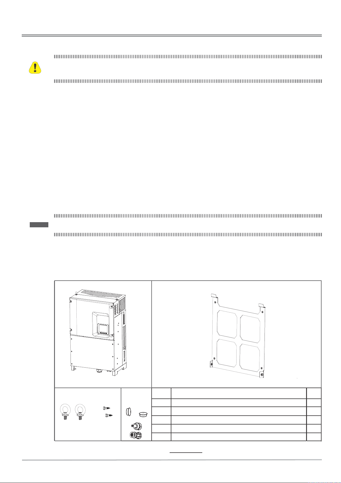
- after opening the package, please check the contents of the box. It should contain the following:
(B)
(C)
(D)
REF. Description Q.ty
A APV-S-.... Inverter 1
B Mounting bracket 1
C2 Lifting Bolts and 2 M8x25 hexagonal head screws 2+2
DPlastic caps 2
Figure 1 : Packaging contents
Caution
(E)
EMC 4 Connectors male and female 24

11
Open the packaging carefully and make sure that:
- no parts of the equipment have been damaged during transportation,
- the equipment is that actually ordered.
Please notify the local sales office if you notice any damage or if the equipment supplied is in complete or not
what was ordered.
Open the box and remove the accessories as well. And proceed as described below.
Removal of the inverter from the box can be carried out as shown in the figure. Using hands on the four slots
3.3 Storage
This equipment must be stored in a dry place within the specified temperature range, see chapter “11. Specifi-
cations” on page 79.
24 If the crate is stored correctly it can be stacked for a maximum of 4 crates. Do not stack other
products or materials on top of it.
Figure 2 : Packing Box and slots for extraction of the inverter from crate
given on right and left bracket and using bottom stand the inverter can be taken out of the box.
12
Changes in temperature may lead to the formation of condensation inside the equipment. This is acceptable
in certain conditions but not when the equipment is in use. Therefore it is always important to ensure that
there is no condensation in the equipment before connecting it to the power supply!
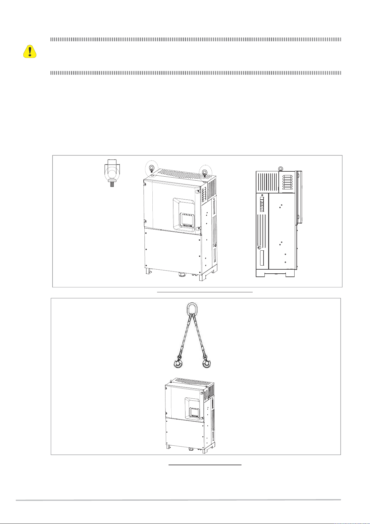
3.4 Handling the equipment after unpacking
The equipment can be handled with chain hoists or crane after installation of the two transport brackets .
The user need to screw the transport/lifting bolt as shown in the below figure. The tightening torque = 25 Nm.
See Figures 4 and 5. Alternatively, it can be handled by using the appropriate handles, see Figure 6.
Figure 3 : Mounting of transport brackets for handling with hoist
Figure 4 : Handling with hoist and two cable tie rod
Caution
20
36

13
Figure 5 : Manual handling
3.5 Disposal of the device
The APV-S inverter can be disposed of as electronic waste according to national regulations in force for the
disposal of electronic components.
14
4. Description of the RADIUS APV-S inverter
4.1 Introduction
The Radius model APV-S inverter is a multistring inverter designed to:
convert direct current (DC) from a PV generator into alternating current (AC) suitable for connection to a
3-phase public grid.
At the application level, the range of string inverters consists of main product line:
- Advanced Energy APV-S-AE
This is very extensive and flexible, intended mainly for photovoltaic roof arrays with complex tracking and ir-
radiation features.
For more information and advice on the ideal configuration for your PV plant, please contact Rishabh’s pre sales
service and see the latest updated SW version of the Radius Planner configurator, downloadable free of charge
from www.rishabh.co.in.
The main product line offers the following power levels:
AC Power Advanced Energy
ing on the model, the APV-S inverter can have 2 MPPTs.
Advanced Energy
3MPPT
• APV-S-AE is supplied with display KA (models APV-S-..k-AE-TL-.....-KA) for th e 34 kW models,
APV-S-50k-AE-TL-.....-KA models
50 kW APV-S-50k-AE-TL-...
APV-S-50k-AE-TL-3...
nDepend

15
4.2 Block diagrams APV-S
DC Fuse
(1)
DC Switch (2)
DC Fuse
(1)
DC Fuse
(1)
DC EMC
Filter
Varistor Varistor Varistor
DC EMC
Filter DC EMC
Filter
MPPT 1
MPPT 3
MPPT 2
Insulation
control
3 LEVEL INVERTER
1
3
2
DISPLAY AND HUMAN INTERFACE
REGULATION BOARD
Residual
current
monitor
LCL
Filters
2 Grid
Parallel
Relay
MAINS
READING
Varistor
AC EMC
Filter
APV-S-20k- -TL-3AE -SFCX-KA
AC Mains
PV PanelsPV PanelsPV Panels
(1) -F models only
(2) -S models only
Figure 6 : Block diagrams APV-S-AE
Note! The unit is equipped with an automatic circuit breaker conforming to the safety requirements specified in VDE0126-1-1.
The block diagrams are show for models AE. See section 11 for the number of strings for each MPPT channel and the number of
MPPTs for each model.
4.3 Installation notes
APV-Sisavailableinseveralcongurationsthatintegratethefollowingdevices.
Forfurtherinformationandconnectiondetails,refertothechapterspecied:
• S DCcircuitbreaker,seechapter“6.11DCcircuitbreaker”onpage31.
• F FusesontheDCside,seechapter“6.7DCsidefusesandstringcurrentmonitoring”onpage27.

16
4.4 Device identification
4.4.1 Data plate
The data plate with details of the specific model is attached to the left side of the inverter.
4.4.2 Model identification (Type)
APV-S -XXk- XX -TL -X X X X X -XX
Display KA = advanced keypad
Grounding kit X = not included
Interface protection system to CEI-021
standard and AC3 contactor
(not available)
X = not included
C = included
DC fuses and Broken string recognition F = included
DC circuit breaker under load S = included
MPPT numbers 2 = 2 MPPT
Transformer TL = not included
Model AE = Advanced Energy
Inverter power in kW 50k = 50 kW
PV inverter, APV-S series
Figure 7: Data Plate
RISHABH
RISHABH INSTRUMENTS PVT LTD
F-31, MIDC, SATPUR, NASHIK - 422007
Ph: +91 2532202019
Web: www.rishabh.co.in
D.C. INPUT
Max. Input Voltage .............................. 1000V
MPPT Voltage Range .......................... 520-800 V
Max. Input Current .............................. 2x33.7 A
A.C. INPUT
Nominal Power .................................... 34 kW
Nominal Voltage .................................. 3x400 V
Nominal Output Current ..................... 49.1 A
Nominal Frequency ............................ 50/60 Hz
Temperature Range ............................ -20°/60°C
Waterproof Class ................................ IP65
GRID TIE 3 PHASE SOLAR INVERTER
Model:
APV-S-50k-AE-TL-2SFXX-KA
Sr No: RI-2017075021

17
5. Installation
5.1 Safety instructions
A) Do not remove the upper casing. The inverter contains no user-service able parts. All servicing must be
performed by qualified service personnel. All wiring and electrical installation should be performed by
qualified service personnel and must meet national requirements.
B) Both AC and DC voltage sources are terminated inside the APV-S Inverter. Please disconnect these
circuits before servicing.
C) When a photovoltaic panel is exposed to light, it generates a DC voltage. When connected to this equip-
ment, a photovoltaic panel will charge the DC link capacitors.
D)
Energy stored in the equipment’s DC link capacitors can be an electric shock hazard. Even after the unit is
disconnected from the grid and photovoltaic panels, there may still be high voltages in the APV-S inverter.
Do not remove the casing (terminal side) until at least 10 minutes after disconnecting all power sources.
E) This unit is designed to feed power to the public power grid (utility) only. Do not connect this unit to an
AC source or generator. Connecting the inverter to external devices could result in serious damage to
your equipment.
F) Although designed to meet all safety requirements, some parts and surfaces of the inverter are still hot
during operation. To reduce the risk of injury, do not touch the heat sink at the back of the APV-S inverter
or nearby surfaces while the inverter is operating.
5.2 Selecting the Installation site
• D o not install the inverter on structures made of flammable or thermolabile materials.
• The mounting location and method must be suitable for the weight and dimensions of the inverter.
Choose a wall or solid vertical surface that can support the APV-S inverter.
• DO NOT install the inverter in locations at risk of explosion or near easily inflammable materials.
• Never install the inverter in an environment with little or no air flow or in a dusty environment. This could
under mine the efficiency of the inverter.
• Mount on a solid surface, the mounting location must be accessible at all times.
• Mount the inverter in a vertical position or with a maximum backward tilt of 15°. The connection area must
point downwards. Never install the device with a sideways tilt. Do not install horizontally. (See figure below).
15° MAX 15° MAX
Figure 7 : Installation warning
• The ambient temperature should be -20 ... +50 °C to ensure optimal operation.
• Do not expose the inverter to direct sunlight to avoid any reduction in power due to excessive heating.
• Do not install the inverter in living areas, the noise caused by the machine could affect daily life.
Warning!
Warning!
Caution

18
• Be careful not to obstruct the slits or the equipment cooling systems.
• DO NOT place anything on the inverter while it is working.
5.3 Mounting
The inverters must be positioned so as to ensure free movement of ventilation air around them and facilitate
wiring and maintenance operations.
• Maximum permissible inclination 15° with respect to the vertical
• Minimum upper and lower distance 400 mm and 620 mm
• Minimum distance between drives 250 mm
OK
OK
NO 250 mm
(9.84")
400 mm
(15.74")
620 mm
(24.41")
250 mm
(9.84")
Figure 8 : Free movement of ventilation air and Minimum distances
5.3.1 Mounting the device on a wall
10.6
15.5
28.2
Figure 9 : Wall-mounting bracket dimensions

Top@12
19
(1)U se the mounting bracket as a template, ensure it is positioned horizontally.
Drill 4 holes in the wall in correspondence with the holes on the bracket shown in the figure.
Attach the bracket to the wall with 4 M10 screws (not supplied).
The size of the holes depends on the wall material and the anchorage system used(e.g. expansion plugs).
(1)
(B) (B)
(1)
Figure 10 : Mounting bracket fixing
5.3.2 Mounting the inverter on the bracket
(2) L ift the inverter and hang it on the mounting bracket at the top, then rest it on the wall.
(3) T ighten the two fixing screws (B) (M8x25 , one on each side) with a 13 socket wrench. The screws (B) are
supplied in the packaging.
(4)F ix the 2 end caps (C).
Ensure that the installation of the inverter is stable by trying to lift it from the bottom. The inverter must
remain securely in place.
(2)
(C) x2
(B) x2
(3)
(B) x2
(4)
Figure 11 : Fixing the inverter on the bracket
Attention
Caution

20
6. Electrical Connection
6.1 System Diagram with Inverter and Electrical connection
• PV Panel: Supplies DC power to the inverter
• Inverter:ConvertsDC(DirectCurrent)powerfromthePVpanel(s)toAC(AlternatingCurrent)power.The
inverterwillalwaystrytoconvertthemaximumpowerfromyourPVpanel(s).
• Utility:Referredtoasthe“grid”inthismanual,thisisthewayyourelectricitycompanyprovidespowertoyour
place.
Figure 12 : Schematic diagram of the system
Note! The system configuration depends on many factors (module type, production target, AC connection, installation site, current
regulations, etc.) and must therefore be designed, built, and decided by a qualified technician.
The Radius Planner program, downloadable from www.rishabh.co.in, can help you correctly size the PV module strings.
6.2 Safety
Connect the ground connector to the terminal (PE) of the APV-S inverter.
Thegroundconductormustbethersttobeconnected.
If replacing the APV-S inverter, the ground connector must be the last to be disconnected.
High voltages exist when the PV panel is exposed to the sun. To reduce the risk of electric shock, avoid
touching live components and treat connection terminals carefully.
The DC cable must be disconnected before disconnecting the AC cable.
The DC circuit breaker (only on models APV-S-TL-..k-S..) can operate under load.
Operation to be performed by specially trained personnel.
Riskofelectricshock.IfthePVeldisilluminated,voltageispresentontheDCside.
There is voltage on the input terminals even if the DC circuit breaker (see Figure 26 on page 31) ) is
in position 0
.
Warning!
Table of contents
Popular Inverter manuals by other brands

Huawei
Huawei SUN2000P-450W-P quick guide

Veichi
Veichi SI30 series manual

Kaco
Kaco Powador 2500xi operating instructions

Sungrow
Sungrow SG1100UD Series Operation and maintenance guide

Somogyi Elektronic
Somogyi Elektronic Home MX 202 instruction manual

Ingeteam
Ingeteam Ingecon mWind Interface installation manual


Thermo King
Thermo King 1100 user manual

Trannergy
Trannergy PVI 5400TL user manual

EmergoPlus
EmergoPlus PowerXtreme XS20 user manual

Power Electronics
Power Electronics SD 500 Series Hardware and installation manual

Generac Power Systems
Generac Power Systems GUARDIAN SERIES overview

MPP Solar
MPP Solar PIP-HS Series installation guide