riva racing S3 300HP User manual
RS16141 Rev. 2/8/2016 BR
SEA-DOO WATER BOX S3/T3 300HP
PART#-RS16141
Applications: Sea•Doo 300 Models 2016
Approximate Installation Time: 1 hr.
Recommended Specialty Tools: Part #
None N/A
Required Materials: Part #
Red Loctite N/A
We strongly reco end the use of a service anual to fa iliarize yourself with the various co po-
nents and procedures involved with this installation. Please note that so e of the original hardware
re oved in the disasse bly process will be used in the installation process. These instructions
have been written in step-by-step for at and refer to illustrations. Read through instructions entirely
before perfor ing installation. Please follow these step-by-step instructions and illustrations careful-
ly.
*** ALLOW ENGINE TO COOL COMPLETELY BEFORE PERFORMING INSTALLATION ***
*** NO SMOKING *** NO SMOKING *** NO SMOKING ***

RS16141 Rev. 2/8/2016 BR
Sea-Doo Water Bo S3/T3 300 HP
COMPONENT IST
Your kit was inspected and verified before being carefully packaged by our staff. Please check package contents before
beginning asse bly. If you have a question about issing or da aged ite s please contact RIVA Technical Support
directly at (954) 247-0705 or by e-ail at tech_support@riva otorsports.co
Packed with pride by _______________________________________________
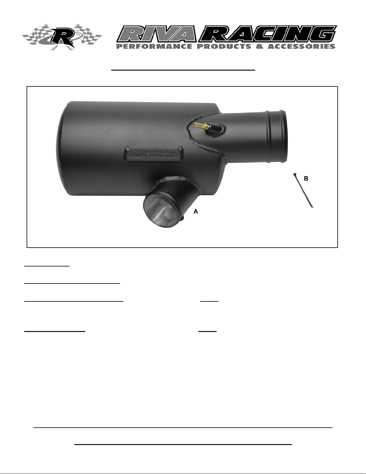
ITEM QUANTITY PART NUMBER DESCRIPTION
A 1 WATER BOX WITH BRASS FITTING INSTALLED
B 1 TY25MX ZIP TIE 7”
RS16141 Rev. 2/8/2016 BR
- INSTALLATION INSTRUCTIONS -
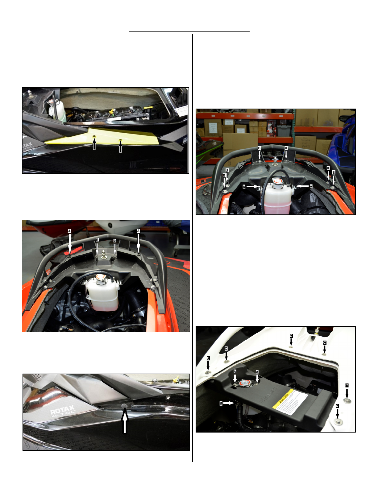
Press the (2) locking tabs (A) on the coolant reservoir to-
wards the reservoir body and lift the reservoir out of its
ounting location. Lay the reservoir to the starboard side
to provide better access to the exhaust.
Re ove (6) bolts (B), nuts and washers holding rear grab
rail in place and re ove grab rail. Caution: Do not drop
nuts and washers into hull. (Figure 4)
Figure 4
RXT-X/RXT/GTX-SC:
Re ove two bolts holding coolant reservoir to deck bea
(A). Pull out on retaining tabs (B) and lower the coolant
reservoir away fro its ounting location. Lay the reser-
voir to the starboard side to provide better access to the
exhaust.
Re ove 4 deck bea bolts and 2 grab rail bolts (C), nuts
and washers. Caution: Do not drop nuts and washers into
hull. Re ove deck bea and grab rail asse bly. (Figure
5)
Figure 5
Re ove or open seat.
RXP-X:
Re ove the two bolts on each side holding the side panels
in place and re ove the side panels. (Figure 1)
Figure 1
Re ove 2 screws (A) and 2 plastic rivets (B) holding vent
cover to rear grab handle and re ove vent cover (Figure
2).
Figure 2
Re ove 2 plastic rivets under side panels re oved previ-
ously (Figure 3)
Figure 3

RS16141 Rev. 2/8/2016 BR
All models:
Disconnect waterlines between exhaust anifold and stock
water box (A)
Disconnect water box overheat sensor (B).
Disconnect engine breather hose fro TOPS valve at rear
of cylinder head (C).
Disconnect exhaust outlet hose fro water box (D).
Re ove rubber strap around waterbox (E).(Figure 6)
Figure 6
At exhaust cla p loosen t-bolt nut enough to allow end (‘T’)
to be re oved fro band cla p. Re ove exhaust cla p.
(Figure 7)
Secure cooling line to hull with supplied zip tie.
Figure 7
Re ove water box asse bly fro hull.
Re ove overheat sensor (A) fro stock water box and in-
stall into RIVA Pro-Series Water Box. NOTE: Apply red Loc
-tite to threads. Do not over tighten.
On stock water box loosen one cla p (B) on exhaust pipe
coupler to allow coupler and exhaust pipe to be re oved
as one unit. (Figure 8)
Figure 8
Thoroughly clean inside of coupler with a non-residual
cleaner.
Liberally coat outside of inlet tube on RIVA Pro-Series
Water box with glass cleaner. Install exhaust pipe with
coupler into water box inlet tube until end of coupler
reaches second raised ring on water box. (Figure 9)
NOTE: Do not tighten hose clamp yet.
Figure 9
Insert water box asse bly into hull.
Align exhaust pipe with exhaust anifold. Note eas-
ure ents in instruction illustrations. Align ent is critical
to prevent exhaust leaks. (Figure 10)
Riva Racing Performance E haust Installation
If a RIVA Racing perfor ance exhaust is to be installed in
the craft this is the point to do so. Follow the installation
instructions for the appropriate RIVA Racing perfor ance
exhaust syste .
- INSTALLATION INSTRUCTIONS -

RS16141 Rev. 2/8/2016 BR
Remember, the water belongs to everyone.
Please ride responsibly and respect the environment!
Technical Support
For answers to questions regarding installation or trouble shooting RIVA Perfor ance Products contact:
RIVA Technical Support directly at (954) 247-0705 or by e-ail at tech_support@riva otorsports.co .
Limited Warranty
RIVA Pro-Series Water Boxes carry a 6-onth li ited warranty to the original purchaser. They are warranted to be free of defects in aterials and work anship under
nor al use and service. Custo er odified co ponents will be void of warranty. This warranty is li ited to defects in the pri ary co ponents only. Finish and/or wear
arks in or on pri ary co ponents are not covered under this warranty.
RIVA Racing’s liability is expressly li ited to the repair or replace ent of the co ponents contained within or associated with this kit. RIVA Racing agrees to repair or at
RIVA’s option, replace any defective unit without charge, if product is returned to RIVA Racing freight prepaid within the warranty period. Any equip ent returned which, in
RIVA’s opinion, has been subjected to isuse, abuse, overheating or accident shall not be covered by this warranty.
RIVA Racing shall have no liability for special, incidental or consequential da ages or injury to persons or property fro any cause arising fro the sale, installation or use
of this product.
No other warranty, express or i plied, including, but not li ited to the i plied warranties of erchantability and fitness for a particular purpose, applies. Various states do
not allow for the li itation of incidental or consequential da ages and therefore the above exclusion or li itation ay not apply to you.
Warranty does not include the expenses related to freight or transportation of parts or co pensation for any inconvenience or loss of use while being repaired. A copy of
the original invoice and a Return Authorization Nu ber (RA#) ust acco pany all warranty clai s.
Warranted replace ent parts will be returned freight collect.
This area intenonally le blank
Figure 10
Install exhaust cla p and t-bolt. NOTE: Check alignment
between e haust pipe and e haust manifold.
Align water box with coupler. Secure coupler. NOTE: Do
not tighten clamp.
Secure water box outlet coupler to water box. . NOTE: Do
not tighten clamps.
Install water box hold down strap. TIP: Spray underside
of water box strap with glass cleaner.
Once water box inlet and outlet couplers are in place and
water box is properly aligned tighten all of the inlet and
outlet cla ps. Note: Do not over tighten clamps.
Reconnect water box overheat sensor.
Replace cooling lines previously re oved. (See Figure 4).
Replace engine breather hose at TOPS valve hose. NOTE:
Do not over tighten clamps.
Replace parts applicable to your craft that were re oved to
access waterbox. NOTE: Apply blue Loc-tite to bolts. Do
not over tighten bolts.
Check bilge for tools, rags, etc. Start craft and run using
flush kit to check for exhaust leaks at connecting points of
exhaust syste . Do not run craft out of water for ore than
two inutes at a ti e
This manual suits for next models
1
Popular Automobile Part manuals by other brands

Generac Power Systems
Generac Power Systems FORD DURATEC 0F9765MNL Engine parts manual

LG
LG ARNU48GBRZ4 manual

Fisher
Fisher Minute Mount L-Series Service parts

Edelbrock
Edelbrock 9300 Installation supplement

SAF-HOLLAND
SAF-HOLLAND SK RB 9022 H Maintenance and Repair Manual

Edelbrock
Edelbrock Victor X 4760 installation instructions

rough country
rough country JEEP 2018 JLU 4-Door Step manual

DAB
DAB BMH - BPH Series Instruction for installation and maintenance

PREVOST
PREVOST H3-41 Maintenance information

Edelbrock
Edelbrock 9629 instructions

Axxess
Axxess OESWC-1761-RF installation instructions

Skyjacker
Skyjacker FJ730ST installation guide


