Riverside FFA-14003 User manual
MODEL NUMBER
FF
A -
14003
RWiiside
I
OWNER'S
GUIDE
ASSEMBLY
AND
ADJUSTMENT
carefully
and
com:Jactly
crated
Your
Sport
Bike
has
been
condition
.
Carefui
assembly
familiar
with
the
workings
assembly
and
adjustment
are
assembly
.
of
your
Riverside
will give
you
and
minor
adjustments
packed
with
your
mach
ine.
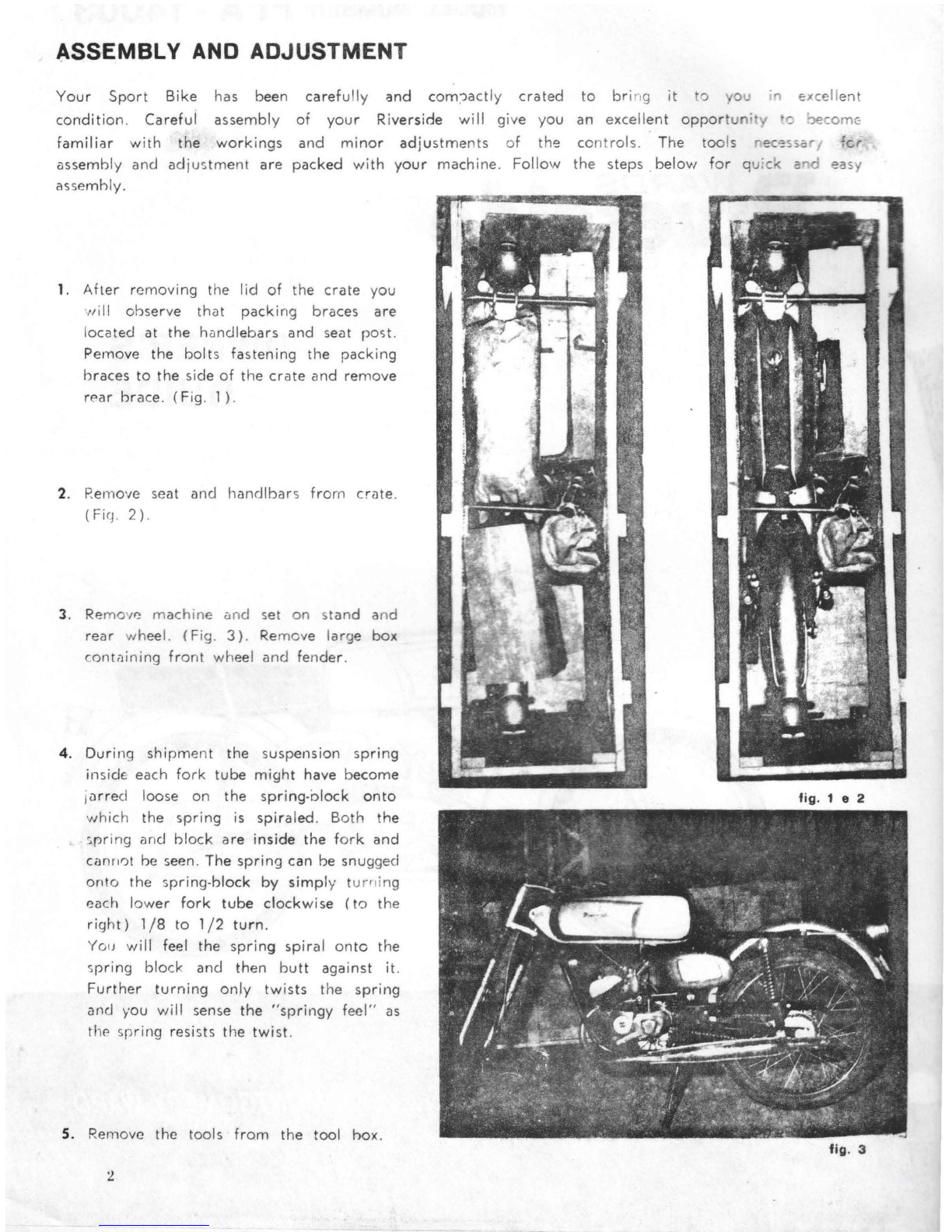
1.
After
removing
the
lid
of
the
crate
you
,,,ill
observe
that
packing
braces
are
located
at
the
handlebars
and
seat
post.
Pernove
the
bolts
fastening
the
packing
braces
to
the
side
of
the
crate
and
remove
rE'ar
brace
.
(Fig
. 1).
2.
Remove
seat
and
handlbar
s
from
crate
.
(
Fi
q. 2).
3.
Re
mov
~
ma
chin
e
and
s
et
on stand a
nd
rear
w
hee
l.
(F
ig.
3)
.
Re
m
ove
large
box
containing
front
wheel
and
fe n
der
.
4.
Dur
ing
shipment
the
suspension
spring
inside-
each
fork
tube
might
have
become
jurrecl
loose
on
the
s
pr
ing-olock
onto
which
the
spring
is
spiraled
.
Both
the
spri
ng
and
block
ar
e
insid
e
the
fork
and
canri0t
be
s
ee
n.
The
spring
can
be
snugged
onto
the
spring-bl
ock
by
simply
t
urni
ng
each
lower
fork
tube
clockwise
(to
the
right)
1/8
to
1/2
turn.
You will feel
the
sprin
g
spiral
onto
the
spring
block
and
then
butt
against
it.
Further
turning
only
twists
the
spring
and
you
will
sense
the
"springy
feel"
as
the
spring
resists
the
twist.
5.
Remove
the
tools
from
the
tool
box
.
of
th'i:!
Fol l
ow
to
br
ing it
t'.J
0 in circelle
nt
an
excellent
oppor
tuni
· -
'='
?eCOmG
co
nt
rols.
The
too
ls r
ec
'::-ssor
for
the
steps
.
below
for
q
u·ck
and
easy
fig. 1 e 2
fig. 3
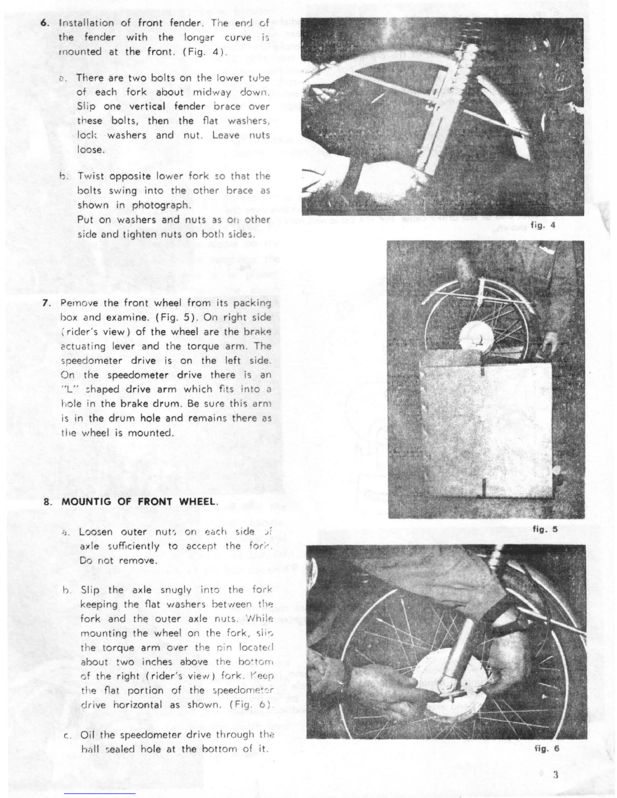
6.
Installat
i
on
of
front
fender
. The
enr
J of
the
fender
with
the
longer
curve
is
m
ounted
at
the
front.
(Fig
. 4 ).
v. Th
ere
are
two
bo
lts
on
the
l
ower
tulJe
of
each
fork
about
midway
dow
n.
Slip
one
vertical
fender
brace
over
these
bo
lts,
then
the
flat
wa
she
rs
,
lock
washers
and
nut
. Leave nuts
loose.
b.
Twist
opposite
lo
wer
for
k
so
that
the
bolts
swing
into
th
e
ot
h
er
brace
as
shown
in
photograph.
Put
on
washers
a
nd
nuts
as on
other
si
de
and
tight
en
nuts
on
bot
h sides.
7. Pe
mov
e
the
front
wheel
from
its
pack
ing
box
and
examine
.
(F
ig. 5 ). On
right
side
i
rider's
view)
of
the
wheel
are
the
brn
k
~
cctuc;t
in
g l
ever
and
the
torque
arm
.
The
sp
ee
dom
eter
drive
is
on
the
left
side
.
On
the
spe
edometer
drive
there
is
an
"L
" sh
aped
drive
arm
which fits into
<J
hole
in
the
brake
drum.
Be
sure
this
ar
m
is in
the
drum
hole
and
remain
s
there
as
the
wh
ee
l is
mounted.
8. MOUNTIG
OF
FRONT WHEEL.
;
i.
Loosen
outer
nut»
on
eoch
si
de
;f
axle suff
ici
ently
to
<1ccept
the
for
;-
.
Do
not
remove.
b.
Sl
ip
the
axle
snugly
into the
forl<
ke
ep
ing
the
flat
washers
bet
we
en
thf!
fork
and
the
outer
ax le nuts. 'Nhile
moun
ting
the
wheel
on
the
fork,
sl
i
r,
the
to
rque
arm
over
the pi n lornte:
cl
about
two inches
above
the
bo•t
om
0f
the
right
(r
i
der
's
view)
fork.
l"
ec:r
the flat
portion
of
the
s
peedo
rne~
-::
r
dr
ive hori
zontal
as
shown
.
(F
ig
.
6)
c. O
il
the
speedometer
dr
ive
throug
h t
h.;,
hall
-;
ealed
hole
at
the
hottom
of it.
fig. 4
fig. 5
fig. 6

9. Remove
headlight
to
make
removal
of
the
handle
bar
packing
bar
easier
. (Fig.
7)
. Remove
the
two
handleba
r hold
down
clamps
and
replace
the
packing
bar
with
the
hand
lebars.
Note
that
the
heavy
portion
of
the
clamps
is
to
·
the
rear.
(Fig
.
8).
Put
on
OM
clamp
without
tightening,
pos
iti
on
hand
l
ebars
where
desired
,
and
allow
them
to
swing
down
while
in
sta
lling
second
clamp
.
Hold
handlebars
where
desired
while
tighten
ing
one
side
a
littre
and
then
the
other
until
both
sides
are
t
i
gh
~
.
10.
Put
headlight
back
on
without
tightening.
Make
sure
the
light
will
make
good
electrical
contact
with
the
bracke
ts,
position
properly
and
tighten.
11. Uncoil
brake
cable
and
put
between
right
fo
rk
a
nd
front
of
frame.
Slip
the
plastic
sleeve
for
retaining
excess cable
over
the
lower
end
of
the
brake
cable
.
Put
the
cable
end
into
the
bracket
as
shown.
fig.
7
12. Draw
cable
down
.to
brake
actuatin
g lev
er
. (Fig.
9)
.
13. Use
wrench
on
large
nut
of
actuating
lever
to
move lever
upward
. Hold in
this
upward
position
while
tighten
ing
cable
clamp
.
14. Slip
cable
through
cable
clamp
and
tigh
te
n
clamp
nut.
Draw
nut
tight
enough
to
bend
and slightly flatten
cable
but
do
!lOt
Q>.Jttr
·ti9htttn because the
damp
or
cable
mqy
be
weakened
~
"d
f~
f
b~k
,
Bend excess
cable
back and
sl
ip end into
plastic
sl~
vc
tor
excess
.
fig. 9
4

15. There
are
two cables hanging between
the
front
forks. One leads back to the
carburetor
and
is
the
throttle
cable.
Th~
other
leads back to the transmission
and
is
the clutch cable. Bring
the
throttle
cable up to
the
right
grip
. Open the
plate on the twist grip. See sketch
A.
Insert the nipple
end
of
the
inn
er
cable
in
to
the
slotted
retainer
as illustrated.
(Fig.
10).
16.
Th
e end of the clutch cable is taped.
Be
careful no o loose
the
nipple on the
end of the cable when removing
the
tape
and
observe how it
is
placed.
Remove
the
screw from the clutch
handle and remove handle. Put
the
end
of the cable through
the
bracket
on
the
handleb
ar
as illustrated. (Fig.
11)
.
Tighten the knurled
nut
to
compress
spring.
17. Push
the
clutch lever,
on
the top
of
the
transmission, to
ward
the
center
of
machine
and
block
in
this position. Do
not remqve the
end
of
the
cable
at
the
engine.
At
the
handlebar
end,
put
the
nipple
through
the clutch handle.
Mount Handle
on
handlebar
bracket
and
slip bolt
through
hole from the top.
Do
not over-tighten
nut
on
the
bol t because
otherwise
handle
wi
ll
bind.
18. The light switch, horn
button
, and
engine
stop
assembly
is
hanging between
the forks. Remove the
strap
on this
assembly
and
mount
the
assembly
on
the handlebars between
the
dutch
lever
and
the
left grip.
fig.
10
Sketch A
fig.
11
5
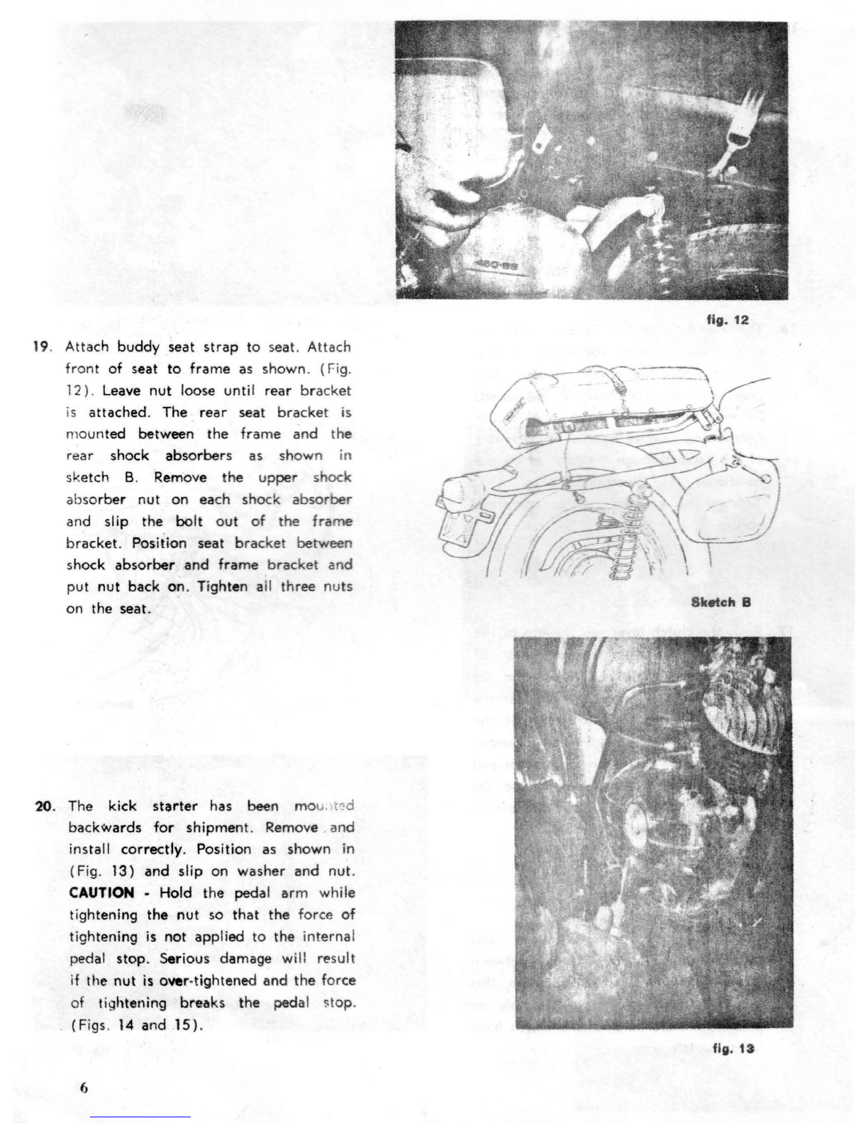
19. Attach
buddy
seat
strap
to
seat. Attach
front
of
seat to
frame
as shown. (Fig.
12)
. Leave
nut
loose until rear
bracket
is attached. The
rear
seat
bracket
is
mounted between
the
frame
and
the
rear shock
absorbe
rs
as
shown
in
sketch B. Remove the
upper
shock
absor
ber
nut
on
each shock
absorber
and slip the
bolt
out
of
the
frame
brack
et. Position seat
bracke
t between
sh
ock
absorber
and
frame
bracket
and
put
nut
back on. Tighten a
ll
three
nuts
on the seat.
20. The kick
starter
has been
mo
u.
1t-:
d
backwards
for
shipmen
t. Remove . and
install
correctly
. Position as shown in
(Fig.
13)
and
sl
ip
on
washer
and
nut.
CAUTION -Hold the pedal
arm
while
tightening
the
nut
so
that
the force
of
tightening
is
not
app
lied to the internal
pedal stop.
Ser
i
ou
s damage will result
if
the
nut
is over-tightened
and
the
force
of
tightening
breaks
the pedal stop.
(Figs. 14 and .
15)
.
6
Hg.
12
Sketch B
fig.
13
' I
:1
t
'I)
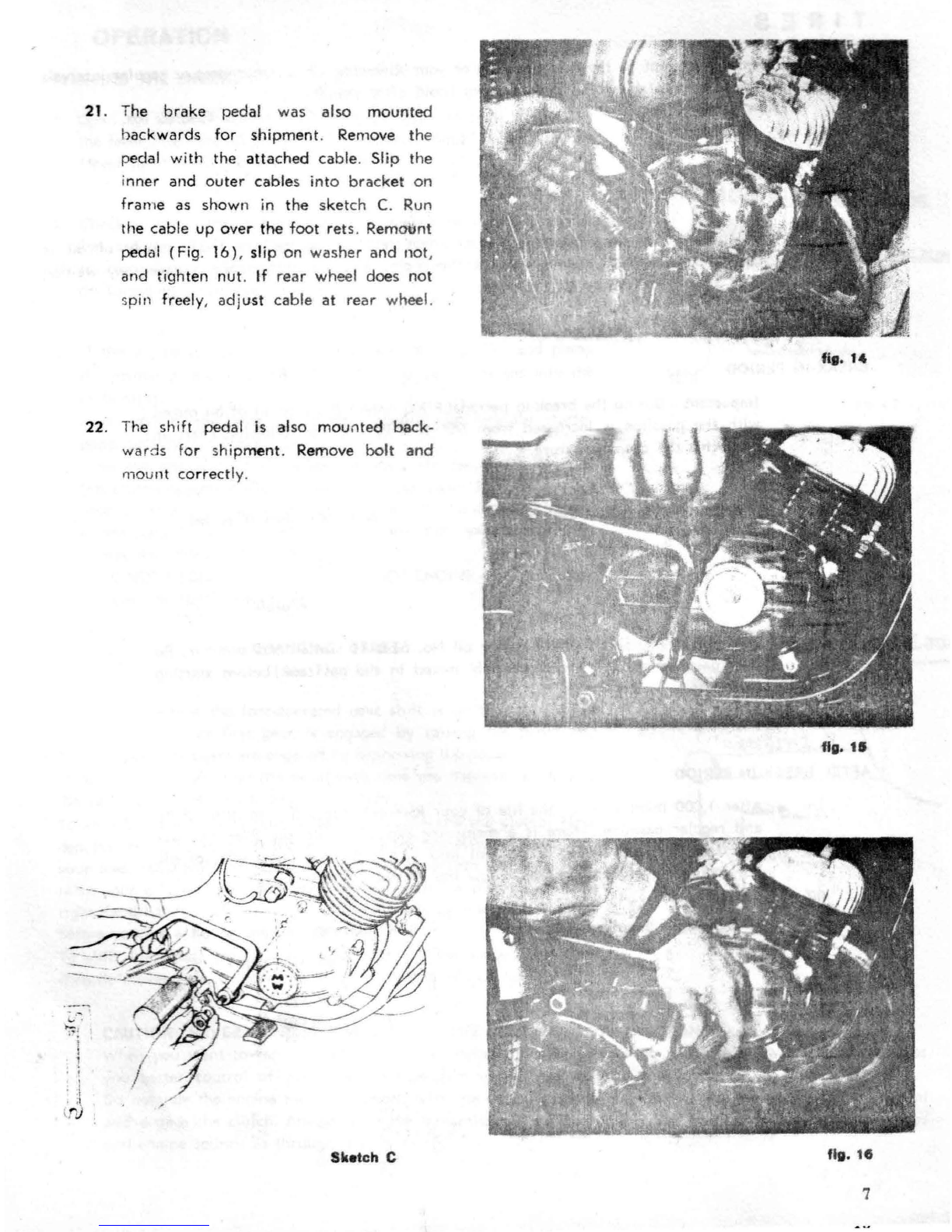
21
. The
brake
pedal was also mo
unted
b
ackwards
for
shipmen
t.
Re
move
the
pedal with the
attached
cable.
Sl
ip
the
i
nner
and
outer
cable
s
into
brack
et
on
frame as shown in
the
sketch
C.
Run
the cable up
over
the
foot
r
ets
. Re
mount
pedc11
(Fig.
16),
slip on
washer
and
not,
and tighten
nut
.
If
rear
wheel d
oe
s not
spin freely, ad
ju
st cable
at
rear
wh
ee
l.
22. The shift pedal ls also mou
nte
d
back
-
wards
fo
r shi
pment
. Remove
bolt
and
ni
ount c
orrect
ly.
I
I
Sketch C
fig. 15
fig. 1
45
7

TIRES
ire
pr
ess
ur
es
are
i
mportant
to
the
safe
h
and
ling
o·
your
·versicle. C you
tires
at
regular intervals
and
be
sure
to keep
them
at
the
following
pr
es
sures
(co
ld
after
i g):
Front
Tire: 22 l
bs
. Rear Tire:
32
l
bs
.
LUBRICATION -
Your R
iv
erside
Sport
B
ik
e two-cycle engine never needs
an
"oil
change";
a
fresh
supply
of
oil is
continu
ou
sly
carr
i
ed
to
the
vital
inner
parts
of
the
engine
with
the fuel.
There
is
never a y waiting
for a
warm
-
up
of
the oil
for
p
roper
lubrication.
BREAK-IN PERIOD
Important -During
the
break-in
period
( 1,000
miles)
the
amount
of
oil mixed
with
the
gasoline
is
increased
from
5%
to
7%.
Use
the
following
chart
in
prepar
ing
the
proper
mixture
.
Gallons
of
Regular Gasoline
5
2
1
1/ 2
(2
qts.)
Add
this amount
of
oil
42
oz.
17 O'Z.
9 oz.
3 capfuls
Us
e
Wards
Riverside 2 cycle engine oil No. 61-8311
winter
and
sum
mer.
Be
sure
gasoline
and
oil
are
thoroughly
mixed in
the
gas
tank
befor
e
starting
engine.
AFTER BREAK-IN PERIOD
After 1,000 miles
and
for
th
e life
of
your
Riverside
use
a 5% mixt
ure
of
oil
and
regular gas
oline
.
There
is a
meas
uring
cap
built
Into
the
filler
bn
your
gas
tank.
For
eac
h qua
rt
of gas
put
into
your
tank
add
one
capful
of
oil.
For mixing
in
larger
quan
t
1.1
es
fellow
the
following
chart.
Gallons
of
Regu
lar Gasoli.,.
5
2
1
1/ 2 (2 qts.)
Add
this amount
of
oil
32 0%, ( 1
qt.)
12
oz.
6
oz.
2
c;1pful1
OPERATION
STARTING
THE
ENGINE
1. Open the petcock
at
the
bottom
of
the
gasoline
tank
by
putting
the lever
in
a vertical position. This petcock should be kept closed
(lever
horizontal)
whenever the vehicle
is
not in use.
2.
Check to see
if
the
transmission
is
in
neutral by rolling
the
bike
forward
slightly.
If
the
bike rolls wit
hout
turning
the
engine over,
te
transmiss
ion
is
in
neutra
l.
If
the
engine
turns
over, see section
on Changing Gears for
instructions
.
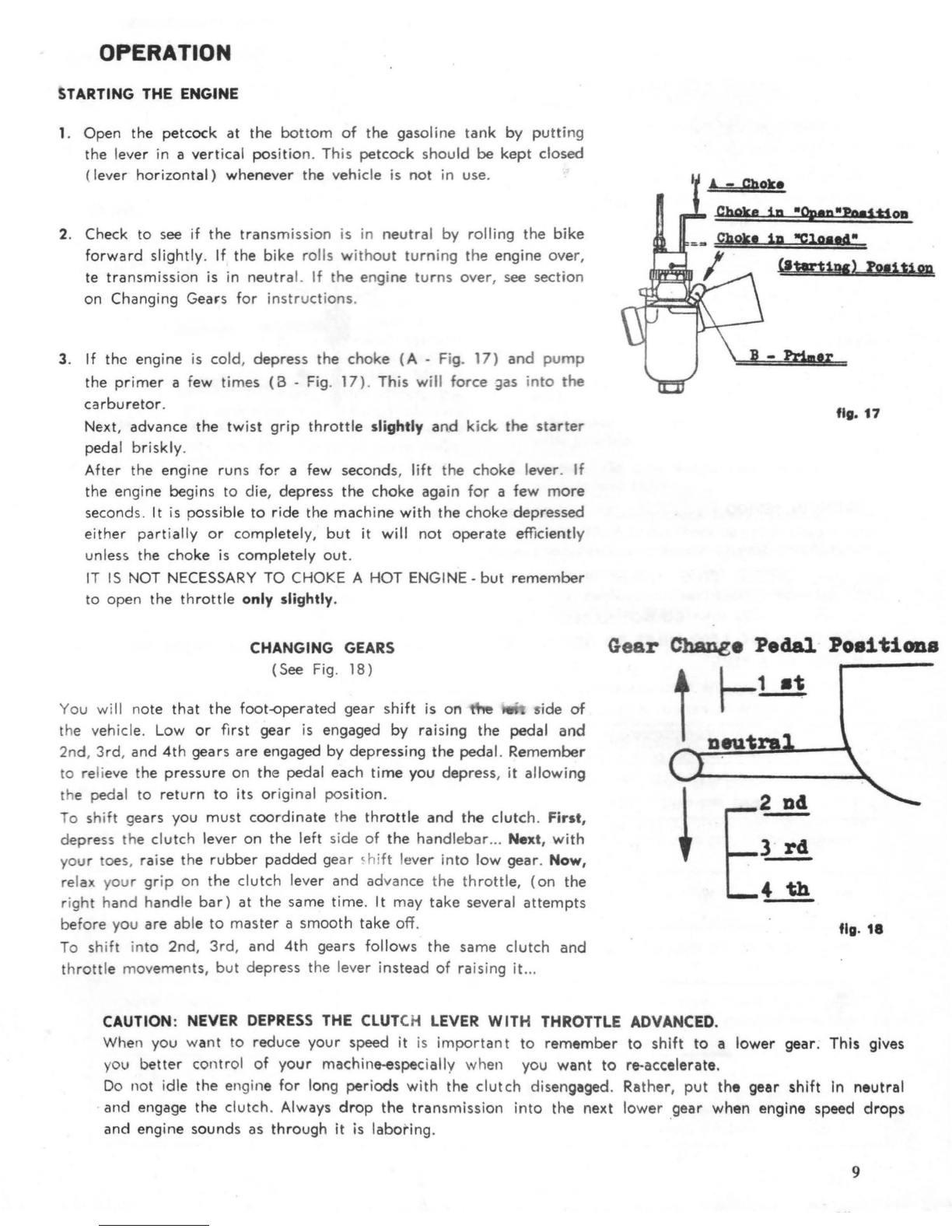
3.
If
the
engine is cold,
depress
the
choke
(A -Fig.
17)
and
pump
the
primer
a few times (B -Fig.
17)
. This will
force
~as
into
the
carburetor
.
Next, advance
the
twist
grip
throttle
slightly
and
kick.
the
starter
pedal briskly.
After the engine runs for a few seconds, lift
the
choke
lever.
If
the
engine begins to die,
depress
the
choke
again
for
a few
more
seconds.
It
is
possible
to
ride the
machine
with
the
choke
depressed
either
partially
or
completely,
but
it will not
operate
efficiently
unless the
choke
is
completely
out
.
IT
IS
NOT
NECESSARY
TO CHOKE A
HOT
ENGINE -
but
remember
to
open
the
throttle
only slightly.
CHANGING
GEARS
(See
Fig
.
18)
You will n
ote
that
the foot-operated gear shift
is
on
the -
~ide
of
the v
eh
icl
e. Low
or
first
gear
is
engaged by raising
the
pedal
and
2nd,
3rd,
and
4th
gears
are
engaged by depressing
the
pedal. Remember
to re
li
eve the
pressure
on the pedal each
time
you depress, it allowing
the pedal to
return
to its
or
iginal position.
To shift gears you must
coordinate
the
throttle
and
the
clutc
h. First,
depr
ess the clutch lever on
the
left side of
the
handlebar
... Next,
with
your toes, raise
the
rubber
padded
ge
ar
<hift lever
into
l
ow
gear
. Now,
relax your
grip
on the clutch lever and advance the
throttl
e,
(on
the
ri
ght
hand
h
and
le
bar)
at the
same
time. It may
take
several
attempts
before you
are
ab
le to
master
a
smooth
take
o
ff.
To
shift in
to
2nd
,
3rd
,
and
4th
gears
follows
the
same
clutch
and
throttle
movements,
but
depr
ess the lever
in
stead
of
raising it...
(HwUv)
lotitipp
fig.
17
Gear
Chane• Pedal
Positions
r--1
•t
fig.
18
CAUTION:
NEVER
DEPRESS
THE
CLUT
CH
LEVER
WITH
THROTTLE
ADVANCED.
When you w
ant
to reduce
your
speed it
is
import
ant
to
remember
to
shift
to a lower gear. This gives
you
better
control of
your
machine-especially when you
want
to
re-accelerate.
Do
not idle the engine for long periods with
the
clutch
disengaged.
Ra
the
r,
put
the
gear
shift
In
neutral
·
and
engage the clutch. Always
drop
the
transmission
into
the
next lower .gear when engine speed
drops
and
engine sounds as
through
it
is
laboring.
9
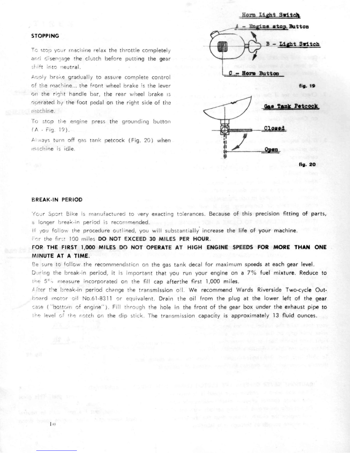
STOPPING
Tc >t
or
your machi ne relax
the
t
hr
ottle
comp
l
ete
ly
M1' i
C:is
eP
ry
ige
the
cl
utch
be
fo
re
putt
ing
the
gear
:!
·.i
ft i
r.
t0
•i
eutra
l.
Armly
b
r
;;i~.
e
grad
ually to
assu
re comf)lete
co
n
tro
l
of
the
ma
chine
..
.
the
front
whee
l brake is t
he
l
ever
0 n the r
ish
t h
andle
bar,
the
re
ar
wh
ee
l b
rake
1~
ope
rated
h:1
the
foot pedal
on
the right side
of
the
rn;;chine.
To
:;
tcp the engine
r:>res
s the
grounding
but
t
on
( A ·
Fi
g. 1? ) .
A: Nays turn off
qas
tank p
et
cock
(Fig
.
20)
when
Horn Li&ht
SwHg
---~==
~
~~~·~t~o
~p~~tton
GI•
;.,..
P•tsos'
1n,,chine
is
i
dle
.
~
fig.
20
BREAK-IN PERIOD
'(c,·J
r Sp'.::rt Bike is
manufa
c
tur
ed
to
very exacting
t~:eranc
e
s
.
Be
cau
se
of
th
is
precision
fitting
of
pa
rts,
a l
ong
er
br
e
a
~-
i
n
peri
od
is
reco
m
men
de
d.
If 1ou fo
lio>"
the
pr
oc
edur
e
out
ii
ne
d,
you will
substant
ially i
ncrea
se
the
life
of
your
machin
e.
r:rJr the
fir
~.
100 miles
DO
NOT EXCEED 30 MILES
PER
HOUR.
FOR
THE FIRST 1,000 MILES
DO
NOT
OPERATE
AT
HIGH ENGINE
SPE
E
DS
FOR
MORE THAN ONE
MINUTE
AT
A TIME.
f:e s
ur
e to fo llo
v.
1
the
re
comm
en
dation
on
the
gas
tank
decal
for
max
i
mum
spee
ds
at
each
ge
ar
leve
l.
During the
bre
ak
-i
n period, it
is
impo
rtant
that
you
run
your
eng
ine
on
a
7%
fuel
mixtu
re
. Reduce
to
Jrie
5"
;,
meas
ure
in
corp
o
rated
on the
fl
ll
cap
aft
er
~he
first 1,
000
miles.
t. f;er t! e break.
-i
n
per
i
od
ch2nge the
tr
a
nsmission
o i
l.
We
recommend
Wards
Riverside Two-cycle
Out
·
h
0or
d
mo~0
r
oil No.61-83
11
0r
equiv
alent. Drain the oil
from
the
plug
at
the
low
er
l
eft
of
the
gear
::a:,e (
"'
bott
0
0m
of engine" ). F
ill
through
the hole in
the
front
of
the
gear
box
under
the exh
aust
pipe
to
i
r•
'! level
c,i
hr::
r·
cJt
<:
h on
the
dip
stick
. The tra
nsmis
sion
capadty
is
approximately
13 fluid
ounce
s.
MAINTENANCE CHECK LIST
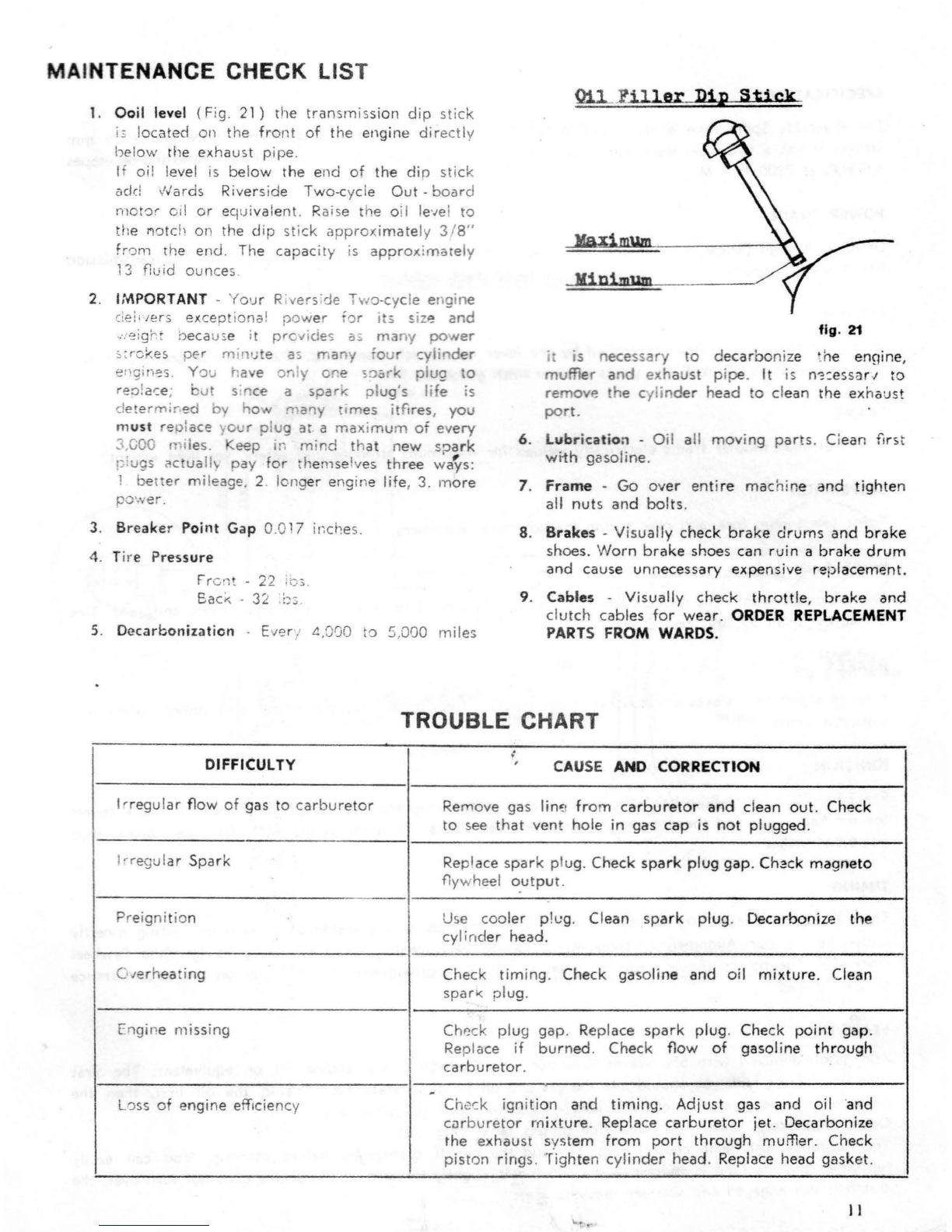
1. Ooil level
(Fig
. 21) rhe
transmissi
on dip
stick
i;;
located
011
the
front
of
the
eng
i
ne
directly
below the
exhaust
pipe.
If
oi! level
is
below
the
e
nd
of
the
dip
stick
add
Nards
Ri
vers
ide Two-cycle
Out
-
board
moto
r oil
or
eq
ui
val
ent.
Raise
the
oil level
to
the ri0tc
'1
on
the
dip
stick
approxim
ate
ly
3 / 8"
fr'Jm the
end
. The
capac
ity is
approx
i
marely
13
fluid
oun
ces
2. IMPORTANT - Y
ou
r Riv
ers
:
de
Two-cycle engine
ci
el; 1ers ex
cept
i
onal
power
'or
i
ts
size
and
.
.-
..
eigr t b
eca
use it
prc
v1
de
s as
ma
ny
oower
;,:
rc~es
per
min
i.,te a
:>
many
'our cylin
der
e P
g
in
~s
.
Yo
u have on
'y
O"e
s
:Jesrk
plug
to
reo
!
ai::e
; but s'n
ce
a
spark
plug
's Ii e is
d
etermi
r.ed by
ho"
m
a11
rm
es
itflr
es
,
you
m
us
t
rep
l
ace
y
our
plug
at
a
max
i
mum
of
every
3 GOO 1
nil
es.
eep
1n
mind
that
n
ew
sp
ark
plugs .c ua
ll
1 pay
for
th
e
mselves
three
wc{!ys:
! ber
ter
mileage, 2. longer
eng
in
e life, 3.
more
po
•.ver.
3. Bre
ake
r
Point
Gap 0.
01
7 ii;ches.
4.
Tire P
ressure
Fr
ont -
22
:c
5_
Ea
c;.;
-
32
!::;;
5. De
carbonization
· Ever/ 4,000
to
5,000
miles
Oil._
_
l'
ill
er
D
ip
Stick
fig.
21
i is
eces
s
ary
to
dec
a
rbon
ize tne
ennine
,
muffler a
nd
exh
a
ust
pipe.
It is
n-;
:e
ssa
r
.;
to
remove
the
cy
li
nd
er
h
ead
to
cl
ea
n the exhaust
port.
6. L
ub
ric
at
ion - O
il
a
ll
moving
parts
. Ci
ea
n
fi
r
st
with
gasoline
.
7.
Frame
-
Go
ov
er
enti
re
macni
ne
and
tighten
all
nut
s
an
d
bolts
.
8.
Brakes
- Visually
check
brake
drums
and
brake
sh
oes
. W
orn
brake
shoes
can
ruin
a
brake
drum
and
ca
use un
necessary
expensive
re
p
lacement.
9.
Cables
-Visual
ly
check
throttle,
brake
and
clutch
cabl
es
for
wear
. O
RD
ER REPLACEMENT
PARTS FROM WARDS.
TROUBLE CHART
t
DIFFICULTY ,
CAUSE
AND
CORRECTION
Ir
regular
fl
ow
of
ga
s
to
carburetor
Remove
gas
lim
i
from
c
arburetor
and
cl
ean
out.
Check
to
see
th
at
vent
hole
in
gas
cap
is
not
plugged
.
!
•regul
ar
S
park
Repl
ace
spark
plug. Ch
eck
spark
plug
gap
.
Ch~ck
magneto
flywheel o.
utput
.
Preignition
Use cooler
ph:
g.
Cl
ea
n sp
ark
plug
.
Decarbonize
the
cylind
er head.
C
1e
rh
eat
ing Check
tim
ing. Che
ck
ga
so
li
ne
and
oil
mixtu
re
. Clean
spar'<
plug.
Engine
missing
Ch
~ck
plug
gap
. R
eplac
e
sp
a
rk
plug.
Check
point
gap
.
Re
pla
ce
if
burn
ed
. Che
ck
flow
of
gasol
i
ne
through
carburetor
.
.
L0ss
of
engin
e
effkie
ncy Ch
eck
ignition
an
d
ti
ming.
Adjust
gas
and
oil ·
and
curburetor
mixtu
re
. Replace
car
b
uretor
jet.
Decarbonize
the
exhaust
s
vst
em
from
port
through
muffler.
Check
piston
rings. T.ighten
cylinder
h
ead
. Replace
head
gasket.
11
SPECIFICATIONS
The P
iv
er
si
cJe
Sport
Bike Model No.
FFA
-
14003
has a
49cc
engine
with
a
40
mm
bore
and a
39
mm
stro e. It has a two-cycle
loop
scavanged
engine
.
The
engine
has
a 9.8 to 1
compres
sion ra io and devel
opes
L!
,5 H.P. at
7800
R. P. M.
POWER TRAIN
Drive is
through
helical g
ea
rs
in
the
tran
sn-.i
ss
i
on
. Final
drive
to
the
rear
whee
l is
by
chain
.
The
ra
nsmi
ss
io
has 4 s
peeds
forward
and
is
operated
by
the
left
foot
pedal.
CLUTCH
illu
ltiple
disc in
an
oil
bath
controlled
by
the
lever
on
the
left
hand
lebar.
The
Riversi
de
Sport
B
ike
will
develop
speeds
to
50
M. P. H., yet
is
a
miser
with
g::isoline.
FRAME
Husky a
ll
-s
teel
tuhular
frame
electrically
welded
for
max
i
mu
m st
rength
and
saf
ety
, y
et
li
ght
weight.
SUSPENSION
Front t
ele
s
C')f)
ing fo rk an
cJ
re
ar sp
ring
lo
aded
:;
h
ock
abs
orbe
rs
.
WHEELS
Ch
rom
e-
pl
ated s
ee
l ri
ms
prov
ide
st
rength
and
add
bea
uty
. T
ir
e size 2.25 x
18
both
front
and
rear
.
Tire
press
ure
s:
front
22 lbs.,
rear
32
l
bs
.
BRAKES
Internal ex pand ing
brakes
on
fro
nt
a
nd
re
ar
wheel
s.
Two
shoes
on
each
wheel
give
added
safety
and
s
moo
ther
sto
ps
.
IGNITION
The F
FA-
14
003
S
po
rt Bike
ha
s a 6 volt
28
watt
flywheel
mag
neto
which
suppli
es
mor
e
than
ample
power
for the hea
cJ
li
ght
and
t
he
co
mb
inati
on
stop
and
tail
lights.
Platinum
points
with
.
017
gap
.
Spark
plug
gap 0.
024
inches
.
TIMING
Th
ere
is
a ti
ming
m
ark
(0
) o n
the
flywheel
an
d
on
the
top
of
the
inside
of
the
eng
ine
casting
directly
und
er
the cyl
inder
. A
lignment
of
these
marks
locates d
ead
center
.
From
th
is
position
turn
the
flywheel
clo
ckwis
e. The p
oin
ts s
hould
begin
to
open
at
33
~
30
' ,
approx
im
ately
1-1
/ 8
inches
on
the
circumference
·
'J
f t
he
fl
yw
he
el .
STARTING
.t..
d
cl
gas
oline m
ix
ed wi
th
5%
War
ds
Riv
er
side T
wo
Cycle-Outbo11rd engine oil
or
equivalent.
The
first
time you
fi
ll
the
t
ank
you s
hou
ld mix
the
gas
a!"ld
oil in a s
eparate
can.
Put
in
the
oil
first
,
then
the
gasol i
ne
. Use
the
measuring
cap
prov
i
ded
- 1
cap
for
each
V
2
gallon
gas
.
Open
the
petcock
u
nder
left
hand
si
de
of
gas
tank
.
(Fi
g.
20)
.
T
he
mach
i
ne
must
be
in
neut
ral
(Fig
.
18)
and
the
clutch
disengaged
before
starting
.
You
can
easily
tel l
when
the
machine
is in
neutra
l
by
moving
it
slightly
forward.
If
the
engine
does
not
turn
over
,
th
e
clutch
is
not
eng
aged
and
you
are
rea
dy
to
start
.
I~

!!JUD LIGHT
HORII
NOT
E
SPORT BIKE WIRING DIAGRAM
g
....
....
•
,,.
u
•
...
p
J
.!
Gll'l' S'llITCH
ROBJI
BUT'l'Oll
UGllll!
STOP
STOPLIGll"'
SWITCH
llACIETO
TAILLIGHT
Allll
STOP
LIGlf!
llITCB
Stop
lamp
is
wired
in
circuit.
If
bulb
is defective, the engine
may
kill
when rear
brake
is
applied
while
eng
in
e is
running.
Table of contents


 Owner's service manual")


