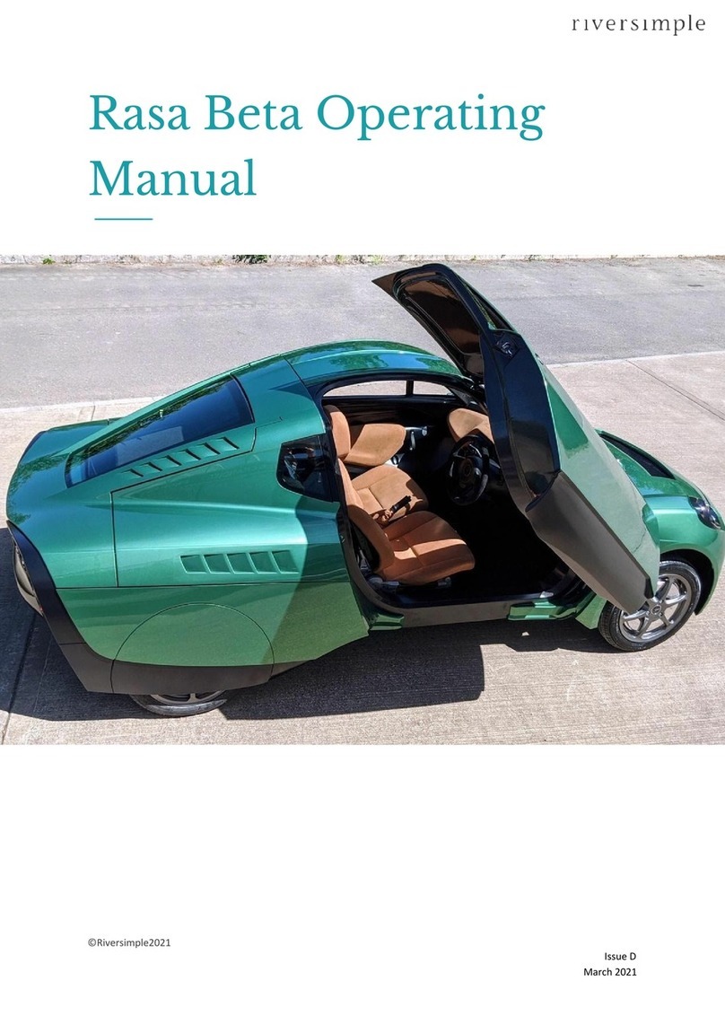
Riversimple Rasa Beta User manual

Operating Manual – Riversimple Rasa Beta
● Amendment record
Issue
Date
Change
Author
A
November 2018
Initial issue
N. O’Doherty
B
February 2020
Update for 12kW FC
N. O’Doherty
C
August 2020
Update for Beta 2 onwards
N. O’Doherty
D
February 2021
Tyre Pressures and
additional ancillary controls
added; H2 Safety Data
Sheets Omitted.
N. O’Doherty
1

Riversimple Operating Manual
Contents
Amendment record 1
1. Introduction and scope 3
2. General safety precautions 3
3. Operating the vehicle 4
4. Refuelling procedure 9
5. General description of the vehicle 10
5.1 General arrangement 10
5.2 Maintaining the Rasa 11
6. Safety systems overview 14
6.1 Crash detection 14
6.2 Hydrogen leak detection 14
6.3 Powertrain isolation 15
Appendix: Hydrogen safety data sheet 15
2

Operating Manual – Riversimple Rasa Beta
1. Introduction and scope
The purpose of this document is to provide information and instruction to allow safe
operation of Riversimple Rasa Beta Fuel Cell Electric Vehicles (FCEV). This includes:
● An overview of the main safety hazards and general precautions;
● Instructions on how to re-fuel the vehicle from the HRS and using compressed
hydrogen gas;
● Instructions on how to operate the vehicle;
● Details of safety systems.
Instructions within this document are applicable to Beta trial vehicles developed by
Riversimple for use on public roads by the general public. These are assigned VIN numbers
ending with six digits sequentially starting from 000001 up to 000017. Users should be
aware that these vehicles are of a trial nature and should be treated accordingly.
This manual should be read by anyone intending to use or operate Rasa Beta trial vehicles
produced by Riversimple.
2. General safety precautions
Compressed hydrogen gas and a high voltage electrical system are installed on Riversimple
vehicles. If not handled correctly these can present significant safety hazards. To minimise
any risks the following general safety precautions must be followed:
● Only trained technicians are allowed to work on Riversimple vehicles;
● Do not store vehicles in enclosed buildings unless approved by Riversimple;
● Do not attempt to raise or tow the vehicle by any means without consent from
Riversimple;
● High voltage enclosures are clearly marked with the high voltage symbol (Figure 1)
and should never be touched, tampered with or opened except by trained
technicians;
Figure 1: High voltage safety symbol
● High voltage wires and connectors are clearly identifiable as bright orange and
should never be tampered with or adjusted except by trained technicians;
● Areas of the vehicle that contain hydrogen components are clearly marked with the
hydrogen safety symbols (Figure 2) and should be treated with caution appropriate to
handling flammable substances and compressed gases;
3

Riversimple Operating Manual
Figure 2: Hydrogen, flammability and compressed gas safety symbols
● Hydrogen gas is extremely flammable and burns with an invisible flame. Keep any
potential ignitions sources well away from the vehicle;
● The hydrogen system working pressure on Riversimple vehicles is 35 MPa (5075
psi). Do not attempt to refuel or connect the vehicle hydrogen storage and delivery
system to sources of compressed hydrogen higher than the system working
pressure;
● If there’s any likelihood of damage to hydrogen components, including the storage
tank and supply lines, do not attempt to operate or refuel the vehicle;
● Hydrogen leak detection systems are installed on the vehicle. In case of a leak the
driver’s visual display unit will display a red triangular H2symbol between the dials
(Figure 3). An audible warning will also sound from the driver’s display. In this
circumstance turn-off and leave the vehicle immediately. The hydrogen supply will
have been isolated and the fuel cell will shut-off once any hydrogen in the supply
lines has been depleted;
●
Figure 3: Rasa Visual Display Unit with warning red triangular H2symbol.
● In case of a serious fault with the high voltage electrical system or its associated
controls the driver’s visual display unit will display a notify stop ‘!’ warning sign
(Figure 4). The audible warning will also sound from the display.
4

Riversimple Operating Manual
Figure 4: Rasa Visual Display Unit with warning red triangular stop ‘!’ symbol.
3. Operating the vehicle
Controls for the Riversimple FCEV differ from those of a traditional manual internal
combustion engine car. Being powered by electric motors there is no gearbox and hence no
gear lever or clutch pedal. There are three driving modes, neutral, forward and reverse, as
shown in Figure 5. Accelerator and brake pedals are laid out in a similar way to a normal
automatic car.
Figure 5: Vehicle driving mode controls (infotainment system may differ from that shown)
A Visual Display Unit (VDU) is incorporated into the dashboard, which communicates vehicle
speed, fuel economy, distance travelled and fuel levels to the driver (Figure 6). Approval
compliant warning symbols are included in the display. The VDU will also display a yellow
(Figure 7) or red (Figure 3) warning triangle in the event of a hydrogen system fault. In the
event of a yellow warning please contact Riversimple so the fault can be investigated. In the
5

Riversimple Operating Manual
case of a red warning triangle the vehicle must be stopped and switched off immediately.
Please contact Riversimple without delay.
Figure 6: Visual display Unit
Figure 7: Rasa Visual Display Unit with warning yellow triangular H2symbol.
The following functional safety features have been implemented on beta vehicles:
● When the car is started it will default to the neutral driving mode;
● It is not possible to change driving modes without being stationary and depressing
the brake pedal;
● Notifications will be given to the driver when the vehicle is in active driving mode
(vehicle “car not ready” will disappear from the dash);
Starting the vehicle
1. Ensure handbrake is up
2. Turn ignition key one click clockwise
3. Wait for the dash to power up (up to 15 seconds, but can be < 1 second if the car
was only just switched off)
4. [Optional] Set Driver ID:
a. The driver ID is shown in the lower-right part of the speedometer - repeatedly
pressing the 'i' button on the centre console cycles this I - II - III - IIII to select
the current driver. If the displayed selection is correct, proceed to step 5
otherwise press 'i' until the appropriate driver ID is displayed.
6

Riversimple Operating Manual
5. The 'car not ready' icon may be displayed above the fuel gauge. As soon as the car
is ready to drive, this is replaced by N (for neutral). Press 'F' (forwards) or 'R'
(reverse) on the centre console to start driving.
6. Disengage the handbrake and drive away. Note that pressing the accelerator pedal
sets the driver Id for this journey.
7. The fuel cell will start up and shut down automatically as needed by the car, with both
the start up and shut down processes
If you don't need to set the driver ID (i.e., it's already correct because the driver is the same
as for the previous journey), the process is:
1. Ensure handbrake is up
2. Turn key 1 click
3. Wait for dash to display 'N'
4. Press 'F' (or 'R'), handbrake down, drive off.
Stopping the vehicle
1. Bring the car safely to a stop using the brake pedal;
2. Engage the handbrake;
3. Turn the ignition keyone click in the anti-clockwise direction to the ‘off’ position.
In case of an accident
If the vehicle is involved in a collision, follow this procedure:
1. Turn off the car as soon as it is safe to do so by turning the ignition key one click in
the anti-clockwise direction to the ‘off’ position;
2. Move well clear of the vehicle;
3. Notify any assistance or emergency responders that it is a hydrogen fuelled vehicle
with a high voltage electrical system;
4. Do not attempt to restart or refuel the vehicle without consulting a trained technician;
5. If the vehicle needs to be moved use a flat-bed lorry; do not tow the vehicle.
Ancillary Equipment
The vehicle is fitted with front and rear demist units operated from the switches as shown in
Figure 5. These units will automatically switch off
The info switch can be used to toggle between outside temp, digital clock and trip. To reset
the trip, while in trip mode hold the button down until it resets, then release.
The vehicle is fitted with an infotainment system comprising DAB radio and Bluetooth
connectivity for audio and phone. Refer to separate instruction manual for use. The user is
responsible for compliance with applicable laws concerning the use of the phone while
driving.
A 5v USB power-only connection is incorporated into the heater control binnacle, for
charging mobile phones(see Figure 11 for location).
7

Riversimple Operating Manual
Headlamp switch
Rotate once to the right for sidelights, and twice to operate headlamps
Rotating to the left operate rear fog lights
Pulling the switch out in any of the above positions operates the interior light.
Figure 8: Headlamp switch
Indicator/ Main Beam Stalk switch
Situated to the left of the steering wheel
Push upwards to indicate right/ downwards to indicate left
Indicators are of the self-cancelling type, however the driver should always ensure indicators
are cancelled when not needed
Pull away from the dashboard to flash
Push toward dashboard to operate main beam, and back away from dashboard to cancel
Leaving the indicator pushed up or down when not in use will operate the parking lamps.
Care should be taken not to drain the battery if this function is used.
8

Riversimple Operating Manual
Figure 9: Indicator/ Main Beam Stalk
Wiper/ Washer Stalk
Situated to the right of the steering wheel.
Push up one click for intermittent/ two for slow/ three for fast.
Push down for a single wipe.
Rotate thumbwheel to vary intermittent speed.
Pull away from dash operate windscreen washers.
9

Riversimple Operating Manual
Figure 10: Wiper/ Washer Stalk
Heating and Ventilation Controls
Figure 11: Heating and Ventilation Controls
10

Riversimple Operating Manual
4. Refuelling procedure
Customers/ users are only permitted to undertake refuelling at the Riversimple authorised
Hydrogen Refuelling Station located at the Abergavenny bus station (Figure 12). The
refuelling receptacle is mounted on the rear left side of the vehicle, as indicated in Figure 12.
Figure 12: Abergavenny Hydrogen Refuelling Station
Figure 13: Refuelling receptacle location
To refill the Hydrogen Tank at the Hydrogen Refuelling Station:
To refill the Hydrogen Tank at the Hydrogen Refuelling Station:
1. Reverse into the green refuelling bay (you need to reverse in order for the nozzle to
reach the car)
2. Make sure the handbrake is engaged and the ignition switched off
3. Open the fuel hatch on the Rasa. On the passenger’s side, reach through behind
the seat and pull the lever towards you. This will open the fuel hatch.
4. Remove the dust cap.
5. Earth the Rasa - connect the crocodile clip at the end of the green cable on the
refueller dispenser to the earthing point next to the Rasa refuelling receptacle.
11

Riversimple Operating Manual
6. Visually check there is no damage to the HRS nozzle. If there is, do not proceed
with the refuelling and contact the Riversimple Service Team.
7. Visually check for foreign objects in the end of the nozzle. If there is, attempt to
remove. If unable to remove, call Riversimple.
8. Connect the HRS nozzle to the Rasa refuelling receptacle. Make sure it is
properly locked. Pushing the Rasa refueling receptacle so that the nozzle clicks into
place.
9. Do not begin refuelling if you if you see the light on the HRS start to flash red. Press
the emergency stop button and call Riversimple. If the light starts flashing at any
point during the refuelling process, press the emergency stop button and call
Riversimple.
10. Begin refuelling by following the instructions on the hydrogen dispenser:
a. Enter the 4 digit Riversimple code
b. Push the green button to start the refuelling sequence
c. The refuelling will make quite a few different sounds such as knocks and/or
low pitch hums. This is quite normal.
d. At the end of fully refueling, the refueller will automatically stop, but make
sure to wait for the instructions on the display screen before removing
the nozzle.
e. In case of partial refueling, the refueling sequence can be interrupted at any
time by pressing the red ”Stop cycle” button. Always follow the instructions
on the screen before removing the nozzle.
f. Refuelling takes no longer than five minutes
11. Disconnect the HRS nozzle by pulling the outer sleeve of the nozzle towards you (a
brief hiss will be audible, which is caused by gas purging from the fill lines). Lift the
nozzle away from the Rasa refueling receptacle. Return the nozzle to the dispenser.
12. Remove the green earthing connection and return it to the dispenser.
13. Replace the dust cap on the Rasa and close the fuel hatch.
14. Drive away.
5. General description of the vehicle
Riversimple Rasa Beta vehicles are designed as ‘local-cars’ to accommodate two
passengers and have a range of approximately 300 miles on one tank of hydrogen. Several
innovative features are incorporated into the design, including:
● A network electric powertrain, which integrates a liquid cooled fuel cell, lithium-ion
capacitors and in-wheel electric motors for propulsion;
● Standard friction braking system integrated with regenerative braking provided by the
in-wheel motors;
● Carbon fibre monocoque chassis and sub-frames
● Capacitors mounted within a custom designed enclosure integrated into the front
sub-frame of the vehicle;
12

Riversimple Operating Manual
● Hydrogen and fuel cell system integrated into the rear sub-frame of the vehicle along
with a hydrogen storage tank and single stage pressure regulator for gas delivery to
the fuel cell;
● Hydrogen receptacle that is compatible with standard hydrogen refuelling nozzles;
● Electronic control for implementing safety systems related to high voltage electrical
isolation and hydrogen safety.
5.1 General arrangement
This section describes and illustrates the general arrangement of the Riversimple vehicle.
Masses and dimensions are provided in Table 1.
Table 1: Vehicle dimensions and weights
Dimensions (mm)
Masses (kg)
Length: 3676
Empty weight: 660
Width: 1610
Gross mass: 910
(empty weight + payload)
Height: 1332
H2 storage: 1
Ground clearance: 118
Figure 14 illustrates side views of the vehicle. Note the location of key vehicle systems and
low seating.
Figure 14: Side view general arrangement
13

Riversimple Operating Manual
5.2 Maintaining the Rasa
The Rasa is a Riversimple asset and is not to be maintained by the user due to the hazards
and specialised skills involved. The only tasks which are permitted to be performed by users
are topping up the washer fluid and inflation of the tyres and even these tasks need to be
performed with special care. If in doubt please contact Riversimple.
To top up the washer fluid the bonnet will need to be removed according to the following
sequence:
1. Open both doors and release the 2-stage clips on each side (see Figure 15). The
inner catch must be released first, then pull the outer catch towards you.
2. Close both doors (Note if this is not done serious damage to the body panels
may result)
3. Slide the bonnet lid rearwards to disengage the lugs at the front of the bonnet from
the retaining holes (see Figure 16). The bonnet may then be lifted away. (Note –
seek assistance if required and do not attempt to remove bonnet in windy
weather conditions)
To re-fit the bonnet:
1. Re-engage the front lugs, ensuring they are both fully located
2. Ensure the bonnet lid is correctly laid in place with the doors closed
3. Open both doors
4. Re-fit the inner stage clips into the slots.
5. Close the outer stage clips
Tyre Pressures:
Front – 38 Psi (2.62 Bar)
Rear – 38 Psi (2.62 Bar)
Note – due to the rear wheel spats it may not be possible to access the inflation nozzle
unless it is below the base of the spat. Contact Riversimple if these tyres require inflation.
14

Riversimple Operating Manual
Figure 15: Two-stage clip (driver’s side)
Figure 16: Bonnet front lugs and location holes
15

Riversimple Operating Manual
To top up the washer fluid remove the cap and fill the washer bottle with water and
screenwash, then ensure the lid is securely fastened. Take care not to overfill (see Figure
17).
Figure 17 Washer fluid top-up
Do not attempt to top up the brake fluid (Figure 18). Contact Riversimple if this needs
topping up.
Figure 18: Brake Fluid Reservoirs – do not attempt to top up.
Do not attempt to jack the vehicle or remove the wheels. In the event a tyre needs repair or
replacement contact Riversimple.
16

Riversimple Operating Manual
6. Safety systems overview
The following safety systems are implemented on prototype Riversimple vehicles, which are
described in the following sections:
● Crash detection;
● Hydrogen leak detection;
● Powertrain isolation;
6.1 Crash detection
Inertia switches are fitted on Riversimple vehicles. If the vehicle is involved in a collision the
switch will cut power to the powertrain contactors and hydrogen solenoid, isolating both the
high voltage electronics and hydrogen supply. The fuel cell will continue to run until residual
hydrogen in the supply lines is depleted.
If the inertia switch has been activated the vehicle should be recommissioned for use by a
trained technician.
6.2 Hydrogen leak detection
Hydrogen leak detectors are installed on Riversimple vehicles (see Figure 19). One sensor
is installed on the roof of the rear sub-frame, which is where all hydrogen components are
installed. Detectors are set to enter an alarm state if a concentration of hydrogen greater
than 4000 ppm (parts per million) is detected (10% of the Lower Explosive Limit) or if the
detector enters an error state.
Figure 19: NTK EGAS-HL Hydrogen Sensors
If the leak detector enters an alarm state the following will occur:
● A ‘H2 system fault’ message will appear on the driver’s VDU and an audible warning
will sound (refer to figure 3);
● Hydrogen supply from the tank will be isolated;
● The Fuel Cell will be shut
● The car will be able to drive on energy stored in the capacitors for a short period.
This should be used to bring the vehicle to a safe stop;
● Turn off the vehicle immediately, exit and move to a safe distance;
17

Riversimple Operating Manual
● The vehicle should be inspected by trained technicians before being operated or
refuelled.
An algorithm is also implemented within the HVC that continually monitors the hydrogen
mass flow rate to the fuel cell based on tank pressure and temperature readings. Limits to
flow are set, which if exceeded also lead to a hydrogen system fault notification and isolation
of the tank, as described above.
6.3 Powertrain isolation
The high voltage DC bus is isolated from both the fuel cell and supercapacitors by high
current rated contactors that must be powered closed. This means that whenever the
vehicle is switched off or loses power the contactors will automatically open, isolating the
high voltage supply. Contactors can also be activated by the inertia switch or emergency
disconnect.
Contactor auxiliary feedback signals are sent to the HVC, which means the system knows if
there is a fault in the isolation system (e.g. a contactor is welded shut) and can take the
appropriate action.
18
Other manuals for Rasa Beta
1
Table of contents
Other Riversimple Electric Vehicle manuals

