Riyue CK3-25K User manual
请注意此使用说明书必须送
至最终用户和维修责任者手
中保管。
This manual should be given to
the person who actually uses the
products and is responsible for
their maintenance.
Fig.3
能效值
型号 吸持功率(VA) 能效等级
CK3-25K
9.0
3
CK3-50K
13.4
2
CK3-65K
14.3
2
安全注意事项
在安装、运行、保养和维修前必须熟读使用说明书,以保证正确使用。
使用说明书中对安全注意事项区分为“警告”、“注意”两个等级。
:不解除的话, 有可能造成死亡或重伤的危险状态。
:不解除的话, 有可能造成中等程度的残疾, 轻伤以及发生物质损伤事故。
并且,即使在 中记载的事项根据情况也有可能导致发生重大事故,所以记载
内容都很重要,请必须遵守。
1. 解开包装
(1) 请确认产品型号、控制线圈电压及适用容量与要求的规格是否一致。
(2) 请检查是否有由于运输等原因而引起的零部件松动或破损现象。
2. 保管
请避免高温多湿、有腐蚀性气体及日光直射的场所,以原包装的状态进行保管。
3. 安装
(1) 请安装于干燥、洁净、牢固的场所。
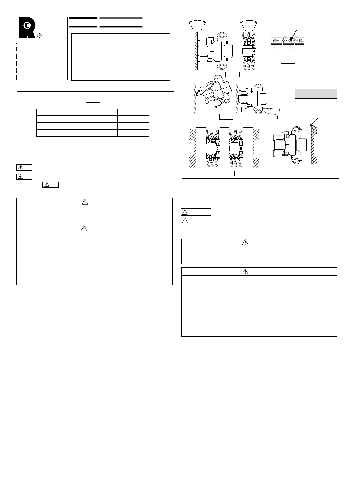
(2) 请垂直安装。允许倾斜角度在 30°以内。(Fig.1)
(3) 导轨安装型可装于 35mm 安装轨上(符合 IEC60715)。安装轨平面布置见 Fig.2。装 、
卸方法见 Fig.3。
(4) 有4个安装孔的场合,选取对角线上的两个孔进行安装。
(5) 务必请拿起本体进行安装。请不要拉住与交流接触器连接的电阻线进行安装,因为
有引发断线,破损的可能。
4. 安装空间
(Fig.4, Fig.5)
(1) 安装间隙需在 Table 1 尺寸以上。
(2) 紧密安装时(连续通电和高频通断的产品视同紧密安装),根据使用条件有可能因温
度上升而造成线圈寿命降低。在此种条件下使用时,推荐使用时产品间的间距大于
5mm。
(3) C尺寸是在 IEC 标准及 GB 标准的接通、分断容量试验条件下的值。
Safety Precautions
To ensure proper use of the product, be sure to read this manual and the other attached
documents carefully before starting installation, operation, maintenance and inspection.
Within this instruction manual, safety precautions are ranked, in order of importance, as
either“Warning” or “Caution”.
Indicates a potentially hazardous situation, which, if not avoided, could
result in death or serious injury.
Indicates a potentially hazardous situation, which, if not avoided, may
result in minor or moderate injury and/or damage to the equipment.
Under certain conditions, improper operation may result in serious injury and/or damage
even if it is labeled only as “Caution”. Every item indicated by either “Warning” or “Caution”
should be considered significant. Be sure to give particular care to those items.
1. Unpacking
(1) Check that the type, coil voltage and contact arrangement match the requested
specifications.
(2) Make sure that no parts have been lost or damaged.
2. Storage
Store the unit in the packing box. Do not store the packing box in a location subject to
high temperature, high humidity, corrosive gas, or direct sunlight.
3. Mounting
(1) Mount in a dry, clean and stable location.
(2) Mounting on a vertical surface. The product must not incline more than 30゜. (Fig.1)
(3) The rail mounting type can be attached on a standard 35mm IEC60715 mounting rail.
See Fig.2 for mounting of the rail on the panel, see Fig.3 for attachment and removal of
products.
(4) If products are provided with four mounting holes, use any two mounting holes on a
diagonal line.
(5) Be sure to life the body of the magnetic contactor and mount it. Do not mount the
magnetic contactor with the connected resistance wire lifted. Doing so may result in
breaking of wires or damage to the product
4. Mounting space
(Fig.4, Fig.5)
(1)Mount the products at a distance of at least that shown in the Table 1.
(2) When units must be installed very closely, the temperature may rise in some conditions
(i.e. the power is continuously supplied for a long time or units that frequently do
switching are installed very closely), and it may shorten the life of the coil. Thus, when
installing units very closely, it is recommended to install the units 5 mm or more apart.
(3) Dimension C is based on breaking test in close circuit of IEC and GB standard.
电容回路切换用交流接触器
Contactor for Capacitor Switching
Type
CK3-25K
CK3-50K
CK3-65K
警告
请不要触摸和靠近通电中的产品,因有触电、灼伤的危险。
维修、检验请在切断电源后进行,因有触电的危险。
注意
因为有引发灼伤、火灾的可能,所以请确保说明书上规定的安装空间。
因为有引发火灾的可能,所以请在接线时按额定电压、通电电流选用符合规范尺寸
的电线,紧固螺钉按照使用说明书规定的力矩紧固。
请不要在切断电源后立即触摸产品,因为余热可能会导致灼伤。
请不要在把顶面安装单元和电阻线从接触器本体取下时使用。
因为有引发火灾的可能。
请用内部回路图(Fig.8)来确认接线后电阻线的接线相顺序的正确性,因为有引发
短路事故的可能。
产品废弃时需按产业废弃物处理。
Table 1
A
[mm]
B
[mm]
C
[mm]
0 10 2
WARNING
●
Do not touch the product or approach it when power connected. Electric shock
or burns may result.
●Turn off the power before starting maintenance or inspection. Failure to do so
may result in electric shock.
CAUTION
●
Install the product in space more than being provided by this manual. Failure to
do so may result in fire or burns.
●For wiring, select wire size suitable for the applied voltage and current. Burns
may result.
Tighten wires with the tightening torque specified in the instruction
manual. Failure to do so may result in fire.
●
Do not touch the product immediately after the power is turned off. As it may
still be hot, burns may result.
●Remove neither head-on unit nor the resistance wire from the main body of a
magnetic contactor. Failure to do so may result in fire.
●For wiring, make sure that the phase sequence of the resistance wire is correct
according to the internal circuit diagram. (Fig.8) Failure to do so may result in
short-circuit.
●Treat the product as industrial waste when discarding.
INA-F05184833c-CE
使用说明书
INSTRUCTION MANUAL
警告
注意
BAB
接地金属
Ground
plate
接地金属
Grou
nd
plate
Fig.4
CAUTION
WARNING
C
接地金属
或绝缘物
Ground plate or
Insulator
飞弧距离
Arc space
Fig.5
注意
Fig.1
30° 30° 30
°
30
°
Fig.2
安装间距
: 400mm 以下
Mounting pitch
: 400mm or less
安装螺钉
M5
M
5 screw

5. 接线
可以连接的电线尺寸及紧固力矩
请参照 Table 2。
6. 使用方法
动作指示块能确认接触器的动作状态。(Fig.10)
请不要触摸动作指示块,因有引发触电、灼伤的可能。
7. 维修、保养
7.1 运转前的检查
(1) 请确认螺钉没有松动。
(2) 请确认是否有电线碎屑、垫片等嵌在产品中。
(3) 请确认控制回路电压在控制线圈电压的允许变动范围内。控制线圈电压的允许变
动范围为线圈电压的 85~110%。
(4) AC 操作时,请确认电压波形是否无畸变,频率为 50Hz 或60Hz。
7.2 定期检查
(1) 运转后尽早进行初始检查,之后请进行定期检查。
(2) 端子的紧固螺钉请定期重新紧固。
(3) 触头不能进行更换。
8. 内部回路图
回路图请参照 Fig.8。
9. 追加辅助触头单元
追加辅助触头单元 FSZ-AS1(侧面安装单元)不能在两侧同时安装使用。只能在左右的任
何一侧安装 1个进行使用。(Fig.11)
5. Connection
Connectable wire size and proper tightening torque
See Table 2.
6. Usage
Operation indicator shows contactor operates or not. (Fig.10)
Do not touch the operation
indicator. Electric shock or burns may result.
7. Maintenance and inspection
7.1 Inspection before operation
(1) Check that all screws are tightened.
(2) Check that there is no foreign matter in the unit, such as wire chips or washers.
(3) Check that the operating circuit voltage is within the allowable voltage fluctuation
range of the coil voltage. The allowable voltage fluctuation range is 85 to 110% of the
coil voltage.
(4) In AC operation, check that operation power supply is sinusoidal waveform (50Hz or
60Hz) without distortion or cave-in etc.
7.2 Periodic inspection
(1) Perform initial inspection early, and perform subsequent inspections on a regular basis.
(2) Check that all terminals are tightened with the proper torque periodically.
(3) Contact cannot be exchanged.
8. Internal circuit
See Fig.8.
9. Auxiliary contact blocks
Two pieces of the auxiliary contact blocks for side mounting “FSZ-AS1” must not be use
on both sides of the contactor simultaneously. Either one block on the right side or on the
left side can be mounted.(Fig. 11)
Table 2
Type
Main terminals
(Connection with clamp terminal) Control
terminals
CK3-25K CK3-50K CK3-65K
【Note 1】【Note 2】
单芯线 / Solid
多股线 / Stranded
多股软线(有压接端子)
Flexible stranded with end
sleeve
[mm
2]
---
1×
(0.75 to 2.5)
2×
(0.75 to 1.5)
2×
(1.5 to 2.5)
电线剥皮尺寸
Stripped length [mm]
---10
可以连接的电线尺寸
Connectable wire size
[mm
2]
0.75 to 10 0.75 to 25 1 to 35 -
【Note 3
】
压接端子的最大宽度
Max. width of cable lug
[mm]
9.7 12.4 16.7 7.7
端子螺钉尺寸
Terminal screw size
M 4 M 5 M 6 M3.5
【Note 4】
紧固工具 / Tool ○+ 2 ○+ 2○-〇○+ 3 ○+ 2 ○-
紧固力矩 【Note 5】
Tightening torque
[N・m]
1.2 to 1.5 2 to 2.5 4 to 5 0.8 to 1
*不接线的端子螺钉,也应全部紧固后使用。
*接线时端子盖的拆卸、安装请按照 Fig.6。
*压接端子请按照 Fig.7那样进行连接。
*接线后,电阻线按照各相的顺序接入正确位置时,请参照图 Fig.8的电路图进行确认。
【Note 1】用2根单芯线进行接线的时候请使用相同尺寸的电线。
【Note 2】多股软线若无压接端子就不能使用。
使用多股软线时必须选用压接端子。
使用压接端子时电线的剥皮尺寸请按照压接端子厂家的指示。
多股线 :多股线单丝根数不大于 7
多股软线 :多于上述单丝根数多股线
【Note 3】使用端子最大宽度以下的压接端子, 圆形压接端子的最大宽度请参照 Fig.9。
【Note 4】○+ 2:菲利普 H型2 号○+ 3:菲利普 H型3 号
○:套筒扳手 ○- :I型螺丝刀 I-1×5.5×L 式B
【Note 5】接线后,对连接电线进行整理时,若发生折弯现象,请再次确认紧固力矩。
*Tighten all terminal screws, even if not use.
*See Fig. 6 for removal and installation of terminal cover when wiring.
*Please connect the cable lug as shown in Fig. 7.
*After wiring, make sure that each resistance wire is connected to a correct phase according
to Fig. 8
【Note 1】When connecting two solid wires, use the same size wire.
【Note 2】Finely stranded wire without end sleeve is not applicable. Use finely stranded wire with
end sleeve. Follow the ferrule manufacturer’s instructions to determine the stripping
length of the wire when using the ferrule.
Stranded wire : Number of solids ≦7
Flexible stranded wire : Number of solids > 7
【Note 3】Use round crimp terminal which width is the size specified at the maximum terminal
width or less. (Fig.9)
【Note 4】○+2:Philips PH2 φ6 ○+3:Philips PH3 φ8
〇:Socket wrench ○- :Slotted-head screw I-1×5.5×L Type B
【Note 5】After alignment or bending back of connected wires, check the tightening torque again.
最大
宽度
Ma
x width
Fig.9
Fig.11
Fig.10
OFF
动作指示块
Operation indicator
ON
CHANGSHU SWITCHGEAR MFG. CO., LTD
(FORMER CHANGSHU SWITCHGEAR PLANT)
No.8 Jianye Road, Changshu Jiangsu P.R. China
Phone : 0512-52842237 52846851
URL http://www.riyue.com.cn
常熟开关制造有限公司(原常熟开关厂)
地址:中国江苏省常熟市建业路8号
电话:
0512-52842237 52846851
URL http://www.riyue.com.cn
Fig.7
电阻线
Resistance wire
连接线
Connected
wire
端子板
Terminal
plate
压接端子
Round climp
terminals
①主回路
①
Main circuit
②
辅助回路
②
Auxiliary circuit
①
-1
①
-2
②
拆卸
Removal
安装
Installation
①
Fig.6
Fig.8
A1 A2
A1 A2
93
94
91
92
1/L1 3/L2 5/L3
2/T1 4/T2 6/T3
1/L1 3/L2 5/L3
2/T1 4/T2 6/T3
Aux. 1NO
Aux. 1NC
This manual suits for next models
2


