Rizzoli L 90 User manual
L - LT - S - ST RANGE
Part 1: Operational Manual for USA/Canada

2

3
The use of economic and ecologic combustibles, the sweet warm of natural fire, the sweet
fragrance of the wood of our forests are the qualities that make indispensable wood fired cookers
in every house.
Your choice fell upon a Rizzoli cooker, result of a tradition started in 1 12 when Carlo Rizzoli began
the production of wood fired cookers with the typical style of the valley in the dolomites. Year after
year Rizzoli continued to refine its cookers using even more advanced technologies, but without
losing contact with the elegance, the beauty and the functionality of the original product.
1. NSTRUCT ONS
1.1 GENERAL NSTRUCT ONS
For the perfect working of Rizzoli cookers it is necessary the correct placing and connection to the
chimney and to the heating system if it is necessary. Before the connection of the device it is
necessary to contact a local chimney sweeper. The installation usually ends with the lighting of the
cooker and the verify of the correct working.
It is necessary to use well dried and good quality wood: it is also necessary to sweep the chimney
and the cooker regularly.
e recommend to read carefully the instructions in this booklet before starting to use the device.
Keep this booklet because it could be useful in case of necessity. Talking about the working and
the installation of Rizzoli cookers and thermal cookers, all the European/USA/Canadian laws,
national and local laws and rules must be respected.
1.2 SAFETY NSTRUCT ONS
• Respect all the safety distances during the installation of the device.
• The grids and the ventilation holes of the device must not be obstructed during the installation
or the use of the device.
• Extracting fans, if working in the same room where the device is installed, might cause problems
when a correct ventilation is not guaranteed.
• hen using the cooker, some parts of the device may be very hot, keep attention not to lean
and not to touch by hand hot parts (frame, plate and doors).
• hen you cook and generally when you use the cooker you must not wear flammable dresses.
• Keep more attention in presence of children.
• Do not place on the device flammable or explosive materials, in particular curtains or do not
place near flammable chemicals and aerosol cans.
• The fire door must always be closed except for lighting operations, fire feeding operations and
during the maintenance operations.
• Check regularly the fume-circuit and, the chimney connection and the chimney itself. At least
every six months of normal use contact an experienced technician for checking and cleaning the
device.
• The plate must be cleaned regularly according to necessities after every use and make regularly
the specific maintenance.
• Before you go away for a long time, be sure that the fire is terminated.
• The first lightings of the cooker and the first seasonal lightings must be done with temperate fire
in order to prevent possible breakings of the internal parts.
4
• After a long period in which you do not use the cooker, check carefully that obstructions are not
present and that the cooker works regularly.
• Use only original or authorized spare parts.
• Do not make any unauthorized modification.
1.3 RECOMMENDED COMBUST BLES
ood fired cookers L - S Range and thermal wood fired cookers LT - ST Range are built to use
wood for burning. e recommend to use good quality wood, dry, seasoned and split. Using good
quality wood is warranty of good heating power and avoid the forming of carbon residuals and
soot. To avoid dissipation of energy and eventual deforming and damaging processes you must
not use excessive combustible (see paragraph 7.1).
1.4 OTHER COMBUST BLES
The use of pre-compressed trunks and coal is not allowed, because the strong heating produced
may damage the internal refractors, the wood-carrying grill, the oven and in general all the parts
directly exposed to fire. Other combustibles and refuses, for example plastic, enamelled or treated
wood or carton must not be burned. Using this materials cause serious damage not only to your
health and environment but also to wood fired cooker and chimney.
The cooker must not be used as incinerator. It is recommended to use only the suggested solid
seasoned dry wood and not liquid fuel.
1.5 PARTS OF COOKERS AND THERMAL COOKERS
L RANGE
LT RANGE
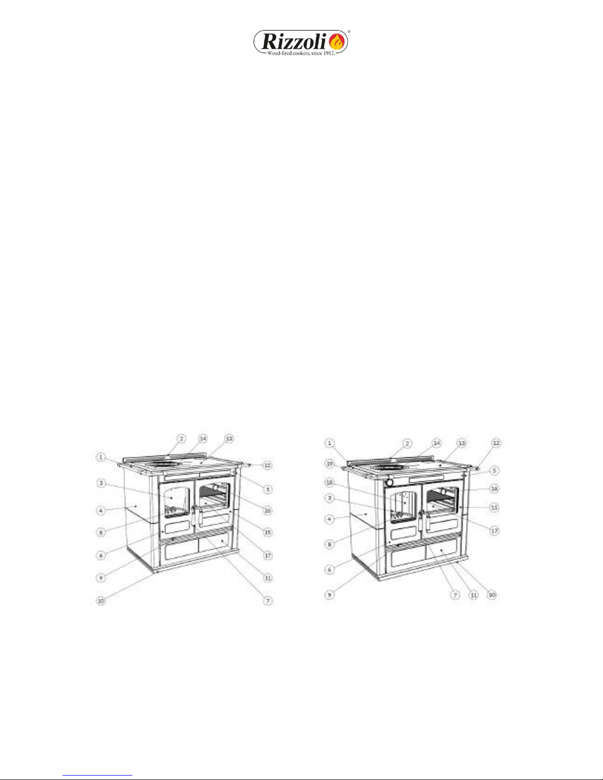
Picture 1 1 Frame 8 Flame keeper 14 Disc or circles
2 Riser 9 Primary and secondary air 15 Oven door
3 Combustion chamber regulation 16 Oven thermometer
4 Side 10 Plinth 17 Oven
5 Starting lever 11 oodbox 18 Boiler
6 Fire door 12 Handrail 19 Boiler thermometer
7 Door opening lever 13 Plate
5
S RANGE
ST RANGE
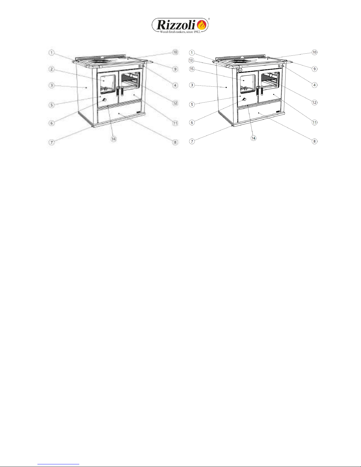
Picture 2 1 Frame 6 Draught regulator 11 Oven door
2 Combustion chamber 7 Plinth 12 Oven
3 Side 8 oodbox 13 Boiler thermometer
4 Starting lever 9 Handrail 14 Primary air regulation
5 Fire door 10 Plate 15 Boiler
1.6 ACCESSOR ES
Together with the wood fired cookers and thermal cookers Rizzoli you will find some accessories
that simplify the installation, the maintenance and the daily use of the device.
• Ash drawer
• Glove
• Poker
• Scraper
• Oil for the care of the plate
• Cleaning oil for the plate
• Abrasive sponge
• Sponge for fire door cleaning
• Hex key for disassembling the handrail
• Restoring screws for the disassembly of the handrail
• Devices for the connection of the exhaust-pipe
• Grill for the oven
• Baking-pan
• Baking-pan holder
• Glove box
• Instruction booklet for use and maintenance
• Green booklet and warranty certificate
• Quality certificate of the refractory bricks
6
2. NSTALLAT ON
2.1 GENERAL NOTES
ood fired cookers and thermal cookers are easy to install; anyway you must take some cares to
avoid damages due to unskillfulness. Before the installation, we recommend to verify the
necessary space, the safety distances, the correct predisposition of the chimney and the possibility
to make the necessary connections. Do not drag the device, move it keeping it lifted from the
floor. The device must not be moved making effort on the handrail or on the handles.
2.2 SAFETY D STANCES
Be sure that the cookers and the thermal cookers that have to be framed have the minimum
safety distances to flammable or high temperatures sensible materials (see paragraph 7.2 and
safety label page 10 in Part 2 Installation Instruction). Rizzoli also produces isolated spacers to
reduce distances. The device is very heavy and must be placed on floor that can support its load
capacity. Follow local codes.
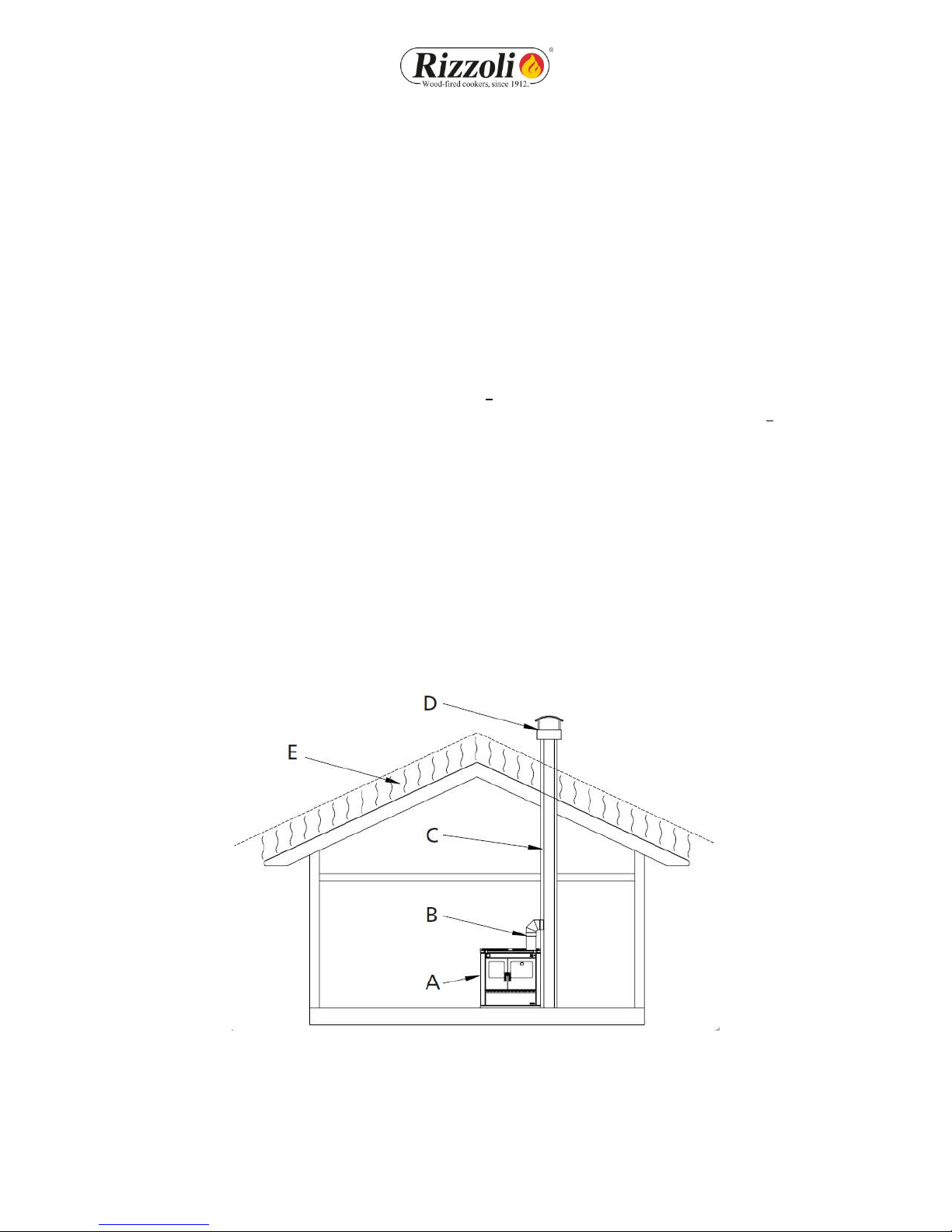
2.3 CH MNEY
Chimney has a main importance for a correct working. ood fired cookers and thermal cookers
are built to insure the maximum efficiency, anyway the performances of the cooker are deeply
influenced by the chimney. If the chimney has defects or does not match the building laws, it is not
insured the correct working of the device. To build the chimney you must use suitable materials,
made to work with high temperatures and according to fireproof laws: it is not important the kind
of material, on condition that it is right and that the chimney is isolated.
Picture 3 - Components of the chimney. A= cooker or thermal cooker, B= conjunction, C= flue, D= chimney,
E= reflow zone

7
2.4 D MENS ONS AND CORRECT FORMS OF CH MNEY
Chimney must be dimensioned in a correct way according to the type of device it is connected
with, minding the environmental and general conditions of the place in which it is placed. The
section of the chimney must permit the flow of the fumes produced by the cooker or thermal
cooker without difficulties, but it must not be too big otherwise the chimney will experience
problems in heating itself and this may generate problems like weak draught and condensation. In
table 1 it is indicated the recommended diameter for the flue according to the model of device
and to the height of the chimney (H). The height of the chimney must be enough to insure the
draught necessary to the chosen model. Bigger is the height of the chimney, bigger is the draught;
if the chimney is lower than 4 m (13,2’), the correct working of the cooker is not insured. The
chimney must not have tortuous parts, horizontal parts or counterslope parts; the number of
bends must be reduced to minimum. In picture 4 you can see some examples of good and bad
chimney connection.
Picture 4 - Samples of correct and incorrect chimney connection.
Table 1 - Indications for the dimension of the chimney according to its height.
Model L - S LT - ST
ø entrance 130 mm (5,1”) 140 mm (5,5”)
ø flue
H < 4 m (13,2’)
Draught not
guaranteed
Draught not
guaranteed
ø flue
4 m (13,2’) < H < 6 m (19,7’) 160 mm (6,3”) 180 mm (7,1”)
ø flue
H > 6 m (19,7’) 150 mm (5,9”) 160 mm (6,3”)
Necessary chimney draft 12 Pa
(0.0482wc)
12 Pa
(0.0482wc)
Picture 5 - H dimension for the sizing of the
flue.
2.5 CH MNEY FLUE
The flue must be well isolated and circular if possible. The flue must not have defects, narrowings
or losses. All the inspection doors must be closed and well sealed. The connection of other devices
to the same chimney is not allowed.
8
2.6 CH MNEY POT
The chimney pot must have an exit section doubled than the one of the chimney, in order to make
easier the exit of the smoke. The chimney pot must be enough tall to lean out over the reflow
zone generated by the roof: if you are not sure about this contact experienced technicians. If you
are in a windy place, it might be necessary to install windproof devices.
The chimney should extend at least 3 feet above the roof surface it penetrates and 2 feet higher
than any roofline or other obstacle within a horizontal distance of 10 feet.
2.7 STOVE P PES CONNECT ON
The connection of the device to the flue must be as short as possible and must not have horizontal
or not much inclined parts. The counterslope parts are forbidden and must be absolutely avoided.
Near the conjunction, flammable materials must not be present. The conjunction must not go
inside the flue. To increase the safety of the conjunction, we suggest to install a washer on the
wall being sure that the connection between the washer and the chimney is walled and well
sealed. Also all the connection must be fixed and sealed. Connections through wall, ceiling and
floor ( see page 4 Part 2 Installation instruction).
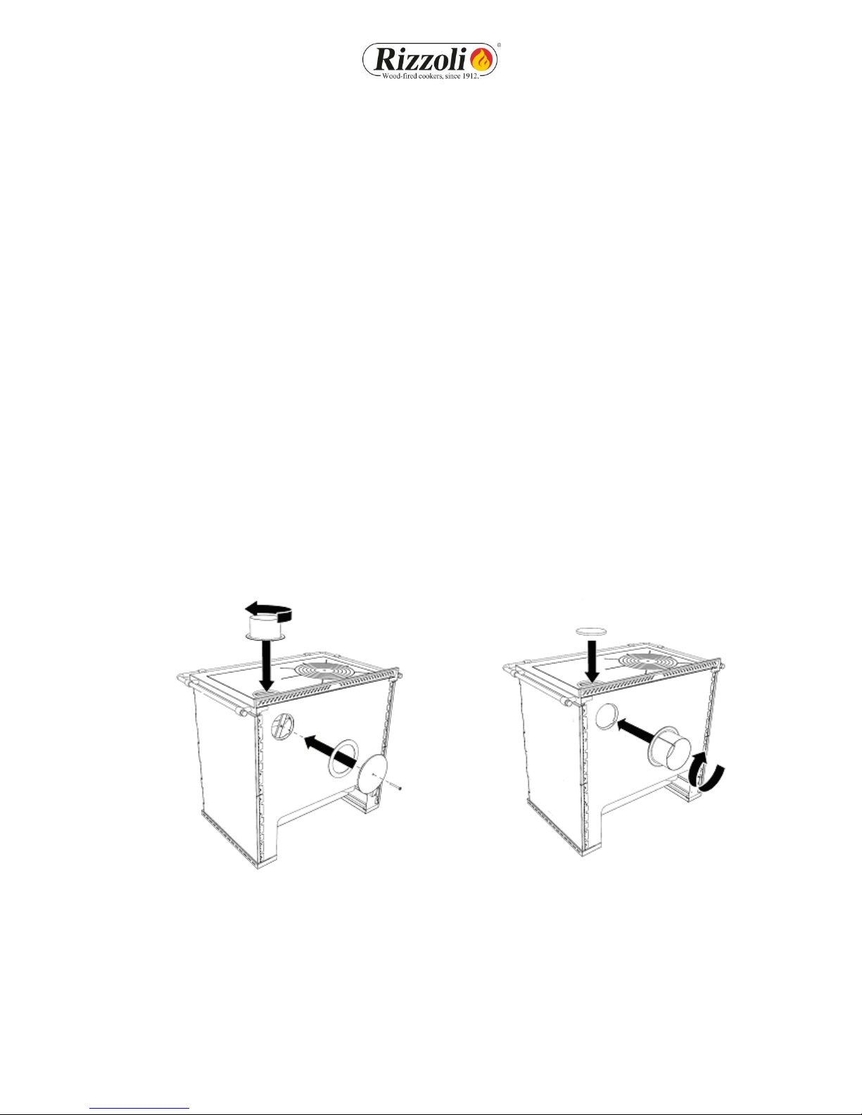
2.8 FLUE OUTLET POS T ON
ood fired cookers and thermal cookers are predisposed to have flue outlets in different positions
(up, back, sides). Before connecting the device to the chimney you must be sure that all the
outlets you will not use are well closed. Eventually, you can make modifications using the devices
given together with the device.
Picture 6 - Multiflue cooker/thermal cooker, predisposition of the correct flue outlet.
2.9 CORRECT CONNECT ON TO THE CH MNEY
If the conduct of the chimney starts from a lower floor than the connection point of the device, it
may be necessary to close the conduct under the connection pipe with fireproof materials. If you
have the chimney behind or up, you have to use the connector with bayonet coupling. This must
be inserted and turned so that it can remain blocked. This connector has a tolerance of about 1 cm

9
(0,39”) to make the installation easier. The tolerance is available according to a single direction
which depends on the orientation of the connector (see picture 7).
Picture 7 - Tolerance for flue outlet on the top and back. The tolerance depends on the orientation of the connector.
The connection with the chimney must be always well fixed and sealed, it must not have
narrowing and must not decrease the usable section of the chimney (see picture 8). If near the
cooker there is flammable material or high temperatures sensible, the connection must be
isolated and the safety distances must be strictly observed.
NO NO NO YES
Picture 8 - Examples of correct and incorrect connection of the chimney.
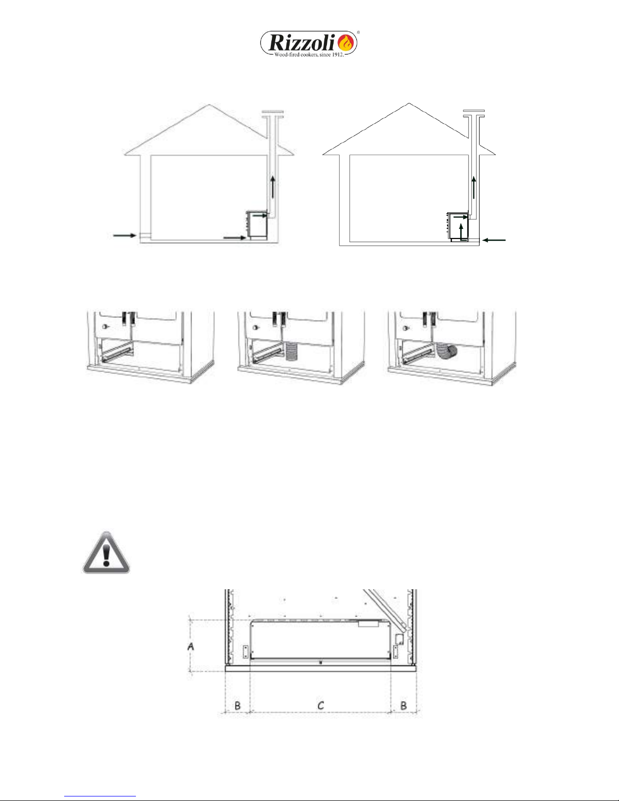
2.10 A R NTAKE
The standard installation of the wood fired cooker and thermal cooker considers that the
comburent air is taken from the room where the device is installed through the air intake of the
device located in the plinth. In this case, in the room must be always ensured the recycle of fresh
air, in particular if the room is small and window and door frames are hermetic. The correct flow
of air in the room must be ensured also in presence of other combustion based devices, aspiring
hoods, chimneys and vent-holes. The air intake in the room must have a minimum surface of 80
cm2. On demand, Rizzoli can give specific valves which can allow the automatic opening of the air
intake only when it is necessary for the correct working of the device in order to warrant a
maximum depression of 4 Pa in the place of installation. The wood fired cookers and thermal
cookers can also be connected so that the comburent air comes directly from outside. In this way,
for the device it is not necessary another air intake in the room of installation. To make this it is
necessary to prepare a conduct connected directly with the external part of the house and make a
direct connection with the air intake of the device. The air intake of the cooker is located inside
10
the woodbox in correspondence of the combustion chamber. For the connection, we suggest to
use a flexible pipe.
Picture 9 - Installation with air intake in the room of installation and installation with air intake directly connected to the wood fired
cooker/thermal cooker.
A B C
Picture 10 - Possible connections of the air intake of the cooker/thermal cooker.
A= External air intake not connected, B= External air intake on the floor, C=External air intake on the wall.
To make the connection easier we suggest to make the external air intake on the floor in
correspondence with the internal part of the plinth, or on the wall through the rear part of the
device (see table 2 and picture 11). Are also possible other solutions for the connection but they
must be decided together with Rizzoli.
WARN NG! Aspiring hoods or extracting air fans in the room may generate
problems to the device if there is not a suited air intake or in case of air intake sub-
dimensioned.
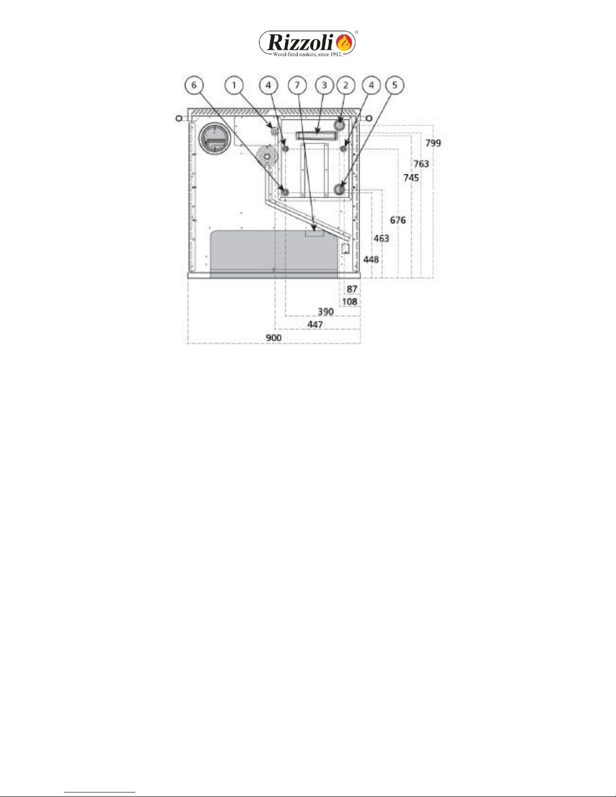
Picture 11 - Rear sight of the plinth of the wood fired cooker or thermal cooker and specifies for the connection with the air intake.
11
Dimensions
Models A B C ø
L 90 248 mm (9,76”) 118 mm (4,64”) 664 mm (26,14”) 95 mm (3,74”)
LT 90 248 mm (9,76”) 118 mm (4,64”) 664 mm (26,14”) 95 mm (3,74”)
S 80 248 mm (9,76”) 118 mm (4,64”) 664 mm (26,14”) 95 mm (3,74”)
S 90 248 mm (9,76”) 118 mm (4,64”) 664 mm (26,14”) 95 mm (3,74”)
ST 90 248 mm (9,76”) 118 mm (4,64”) 664 mm (26,14”) 95 mm (3,74”)
Table 2 - Dimensions for the connection of the external air intake.
WARN NG! For the correct working of the device verify that the passage of
comburent air is not obstructed or, in case of connection with external air intake,
that the air aspiration grill is not obstructed.
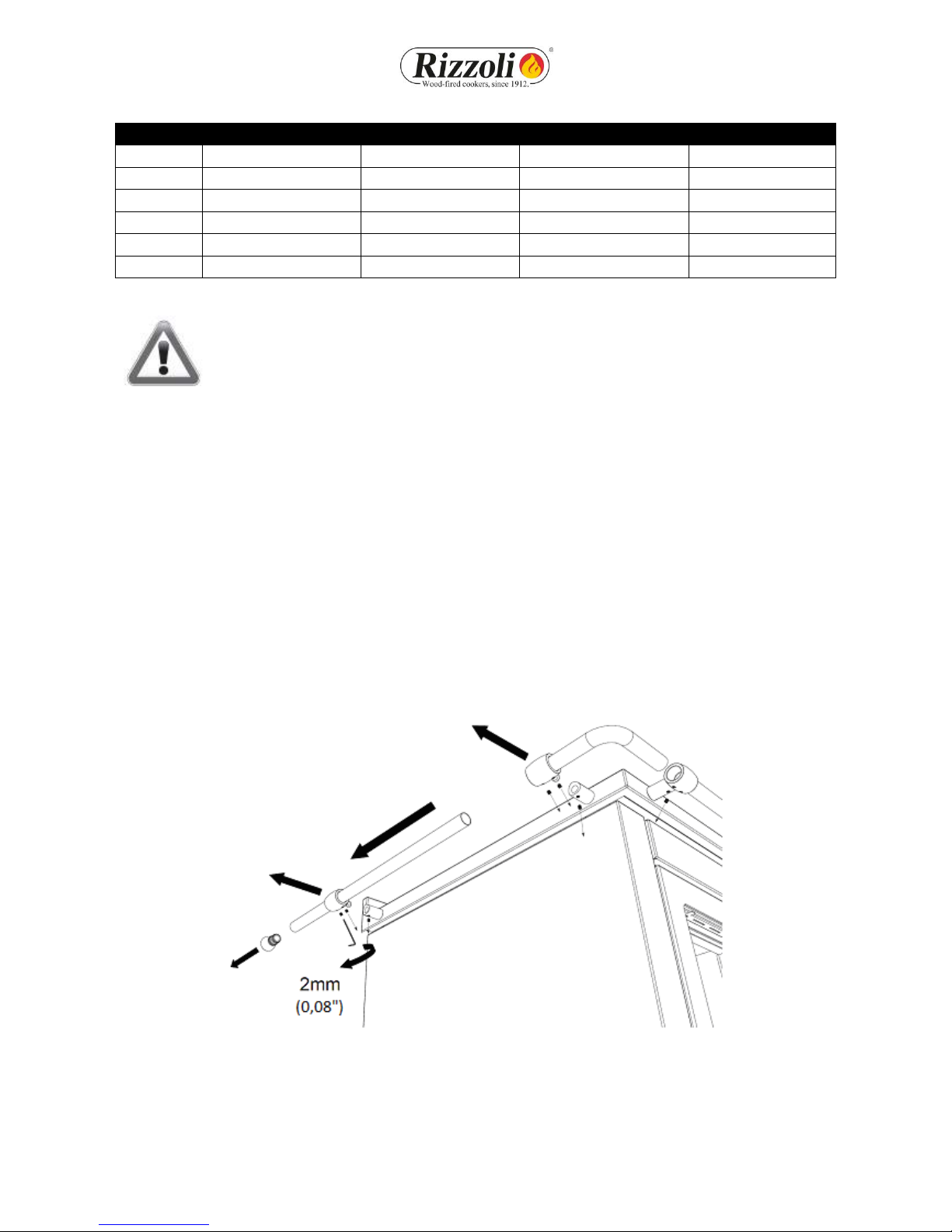
2.11 HANDRA L PRED SPOS T ON
L-S cookers and LT-ST thermal cookers are endowed with handrail on three sides (front, left side,
right side). In some situations it may be necessary to remove the handrail from one or more sides.
To make this operation, you need a star screwdriver and the hex key with the screws given
together with the device. First, you must remove the final part, which is just inserted by pressure.
Then you have to release the hex head screws under the carrying of the handrail where necessary.
Now you can extract the handrail bar from the carryings, then unthread the pommels of the
carryings and the bend of the handrail. Now you must insert the final part where was inserted the
bend before, then remove the carryings with the star screwdriver, replace the fixing screws with
the screws given as endowment and finally close again the hex head screws released before.
Picture 12 - Modification of the handrail

12
Picture 13 - Modification of the handrail
WARN NG! Do not lean flammable objects on the handrail, like kitchen rags
orpinches. Do not hang the linen to dry on the handrail.
2.12 F RST L GHT NG
Before starting to use the cooker, remove the packaging materials in the oven and in the wood
box, remove the stickers and remove the plastic film in which is wrapped the plate and remove
with a rag the most of the oil on its surface. e suggest to make a first lighting of the device just
to verify the correct installation. The first lighting must be done with moderate fire, using little
wood broken in small pieces. In the next lightings you can progressively increase the load of
combustible. During the first lightings some smell due to processing residuals might happen. This
phenomenon is normal, it requires the ventilation of the room and will disappear quickly.

13
2.13 SETTLEMENTS
The refractory mortar used for the internal walling contains always a little moisture that is
eliminated after the first periods of use: so it is normal that the first times you light the cooker or
the thermal cookers a little condensation is being generated. All the refractory materials inside the
cooker experience a settlement process that may generate small holes on the bricks, such holes do
not preclude anyway the working of the cooker. Other settlements may involve other parts of the
cooker so during the heating and cooling phases you might hear light noises. These symptoms do
not absolutely preclude the use of the cooker and fading out till disappearance with the constant
use of the cooker.
14
3. HEAT NG SYSTEM (LT 90 - ST 90)
3.1 GENERAL NOTES
LT - ST thermal cookers are endowed with boiler to use the heating produced by the device
through a system with fluid vector for heating and for the production of hot water. Usually the
system shall be designed according to UNI 10412-2 law by a qualified thermal technician and
installed by specialized staff according to the existing laws and the UNI 10683 law. The LT - ST
Range thermal cookers are endowed with all the necessary predispositions for a correct
installation, every external component (as pumps, valves, acoustic alarms system, pressure
switches, expansion tank) must be obtained by third parts according to the specifies of designer
and installer.
3.2 CONNECT ONS TO THE HEAT NG SYSTEM
Before the lighting of the thermal cooker it is necessary to make the connections to the heating
system. The use of the thermal cooker with empty or not connected to the system boiler causes
the irreversible damaging of the boiler itself. Anyway, it is necessary to connect the going
connector, the return connector and the discharge connector (necessary to empty the boiler in
case of maintenance).
3.3 AUX L ARY CONNECT ONS
According to the system you want to install, there are some auxiliary connectors for facultative
use, but sometimes necessary. These are the connectors for the thermal discharge circuit, the
connector for the detector of thermal discharge valve and the connector for the thermostat. If not
used, these connectors must be covered.
3.4 THERMOSTAT
LT - ST thermal cookers are not endowed with thermostat. If you want to create a forced
circulation based heating system it is necessary to use an external thermostat to control the
working of the circulation pump of the system, according to the temperature of the water in the
boiler. The thermostat must be placed external to the device with the temperature detector
inserted in an suited cockpit in the rear part of the thermal cooker. The thermostat must
guarantee the working of the pump each time the water temperature of the boiler exceeds the set
temperature.
WARN NG! For a longer duration of the boiler of the thermal cooker, you must not
make circulate the water with temperatures lower than 55-60° C. Lower
temperatures generate acid condensation and gas-black on the walls of the boiler.
15
Picture 14 1 Connection thermostat detector Ø 1/2’’ female 5 Return connection Ø 1’’1/4 female
2 Going connection Ø 1’’1/4 female 6 Connection discharge Ø ½” female
3 Connection for thermal discharge detector Ø 1/2’’ female 7 External air intake (optional)
4 Connections for thermal discharge circuit Ø 1/2’’ male
3.5 SAFETY
On every solid combustible based boilers it is not technically possible to break the combustion
immediately as happens for boilers based on liquid or gas combustible according to necessity. For
this reason, it is important to swallow always the produced heating also even if the heating system
does not request that and also in case of lack of AC power. On contrary, the water in the boiler
could boil without possibility of outlet, with serious danger of explosion of the boiler and serious
injury risk for the people present near the thermal cooker. For this reason, we recommend to
follow strictly what is written in UNI 10412-2 law in the various cases and we suggest also to insert
in the system also a boiler able to accumulate the heating in excess produced as sanitary hot
water.
3.6 THERMAL D SCHARGE
For more safety, it is possible to make an auxiliary circuit of thermal discharge connected directly
to the boiler. The thermal discharge circuit is mandatory in case of closed expansion tank
installation.
The thermal cooker has a predisposition for this solution. The thermal discharge system allows to
cool directly the boiler when it is necessary by making flow cold leaking water in a separate circuit
inside the boiler.
The making of the thermal discharge system is under responsibility of the installer. All the
components of the thermal discharge system external to the thermal cooker must be obtained by
third parts according to the specifies of designer and installer. To make this system it is necessary
to make the going and return connections, that are interchangeable, the detector that rules the

16
device must be inserted in the apposite connection bulb. The system, to be effective, must be able
to work and must have availability of cold water also in case of lack of AC power. The safety
devices must be accessible also after the installing for the maintenance and the functional verify.
The functional verify must be done regularly: we suggest at least once a year. The thermal
discharge circuit must not be used for the production of hot water for domestic use. On demand,
Rizzoli can provide a thermal discharge valve suited for its devices.
Picture 15 – Thermal discharge circuit scheme.
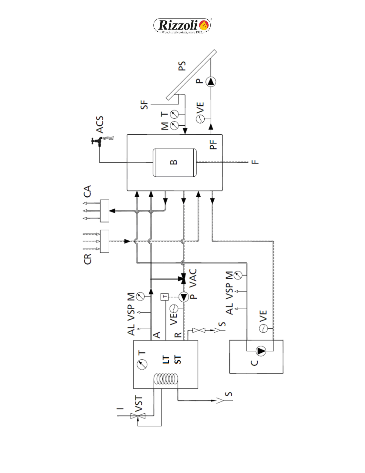
3.7 EXAMPLES
Here are some examples of possible system realization. These schemes are just valid as example
and must not be used in the making of the system. Ask always a thermal technician for an
installation that best suites your needs.
Picture 16 – Simplified schemes for the installing of a heating system with the thermal cooker LT 90 or ST 90 as heat generator.
17
Picture 17 – Simplified schemes for the installing of a heating system with the thermal cooker LT 90 or ST 90 as heat generator.

18
Picture 18 – Simplified schemes for the installing of a heating system with the thermal cooker LT 90 or ST 90 as heat generator.
19
4. USE
4.1 OPERAT ON
During the operation, inside the cooker happens a combustive reaction of combustible (the wood
inserted in the combustion chamber) and burning (the oxygen present in the air of the room in
which the cooker is placed).
The wood fired cooker makes an intermittent combustion: after the lighting, the combustion goes
on till the exhaustion of the combustible but it can be maintained lighted by making another load
of combustible and so on.
The maintenance of the combustion in time is guaranteed by the correct working of the chimney,
which allows to evacuate the fumes and in the same time to feed the flame with comburent air. In
this way, the features of the chimney have a big influence on the correct working of the device.
The combustion of wood requests that the air flow inside the combustion chamber happens in
different points to obtain the maximum efficiency. In particular, it is present a primary air feeding
that flows in the lower part of the combustion chamber by the grill, and one or more secondary air
feedings that flow in the upper part of the combustion chamber.
The primary air is the main air and regulates the combustion speed.
The secondary air allows the post-combustion of the fumes, generating further heating, knocking
down the amount of harmful gas and so improving both the rendering and the impact on the
environment.
Once started the combustion it cannot be interrupted in a safe way: it must be always faded out
naturally with the exhaustion of all the combustible inserted.
WARN NG! For a correct operation verify that the eventual external air intake in
the room and the air aspiration and ventilation grids are not obstructed.
4.2 START NG
To allow an easier lighting of the cooker with cold chimney, wood fired cookers and thermal
cookers are endowed with starting key governed by a rod: if you extract this rod, the key opens.
The opening of the key creates a direct connection between the combustion chamber and the
chimney, in order to obtain a better draught. To light the fire, you can use well dried wood, very
subtly cut, together with the specific products you can find in commerce. The combustion may be
difficult as long as the chimney is cold. The necessary time depends on the chimney and on the
weather conditions. hen the fire becomes powerful you must turn off the key in order to force
the fume to heat the other parts of the device. Both the cooker and the thermal cooker are
designed to work with the key turned off, the use with the key opened does not allow the device
to work at its best and may cause overheating and consequent damages.

20
Picture 19 - Starting key. ith lever outside, the key is open and the starting is easier; with lever inside the key
is closed for the normal working.
4.3 A R NTAKE REGULAT ON
On every model the entrance of oxidising air inside the device is ruled by a valve controlled by a
lever placed below the fire door. The valve is closed in the right position while it is open in the left
position. For the regulation of this device see picture 20. If the device has the flue outlet on the
left side, the regulation of the lever is symmetrical (valve closed in left position, open in right
position).
Picture 20 - Air regulation fire door lever: the valve is open in correspondence of the position indicated with
letter A while it is closed in correspondence of the position indicated with letter B.
The open position is indicated when the device is working. It allows the entrance of the
combustive air necessary to feed the flame. The cooker or thermal cooker cannot work with the
lever in closed position.
In presence of a hood with high draught it could be useful to set the lever at an intermediate
position, in order to obtain a partial opening of the air conduct.
On models S-ST range there is a further regulation: the primary air regulator, placed on the front
part of the cooker, is ruled by a graduated hand gript that operates on the combustion speed. Low
values guarantee less power and more autonomy. High values guarantee more power and less
This manual suits for next models
4
Table of contents
Other Rizzoli Range manuals

Popular Range manuals by other brands

KitchenAid
KitchenAid YKFED500ESS installation instructions

Vulcan-Hart
Vulcan-Hart GH30 Installation & operation manual

GE
GE CBC980 Owner's Manual & Installation Instructions

privileg
privileg SET PV510 IN manual

Bosch
Bosch HDS8045U use and care manual

Viking Range
Viking Range 5 Series VGC Use & care manual


