RMS 1S25 Series Service manual

Visit www.rmspl.com.au for the latest product information.
Due to RMS continuous product improvement policy this information is subject to change without notice. 1S25/Issue F/07/03/2011 - 1/9
Features
Four independent arc fault
tripping zones
1 or 2 arc fault sensors per
zone allowing up to 8 arc fault
sensors per 1S25 module
Trip indication LED for each arc
fault monitoring zone
Non volatile memory ensures
last recorded alarm states are
restored on power up
Nine (9) high speed arc fault
tripping duty output contacts
(Set for latching or self reset)
Zone segregated or common
tripping output configuration
Continuous arc sensor
supervision with sensor fail
LED for each zone
Wide range status input to
block arc fault monitoring
Front panel reset button &
status input
Self supervision watchdog with
healthy LED & alarm contact
Built in test sequence
Wide range auxiliary supply
Introduction
Medium voltage switchgear is a key
element in the power supply chain.
Existing protection systems operate
effectively under most circumstances, but
they are too slow to handle arcing short
circuits.
Arcing faults can occur as a result of
insulation breakdown due to equipment
age & / or poor maintenance.
The degree of damage caused by arcing
depends principally on the duration of the
arc. If an arc lasts only 100ms, the
switchgear needs to be checked & the
insulation resistance measured before
power can be re-established. With a
200ms arc, the power supply will be
interrupted; the switchgear must be
checked; power is re-established only
after minor repairs. In the event of a
500ms arc the supply is interrupted, metal
parts of the switchgear are destroyed &
poisonous gases are emitted. A 1s arc
destroys most of the switchgear & may
cause a fire, injury to personnel & damage
to property.
Technical Bulletin 1S25
Arc Fault Monitor – 4 Zones, 8 Sensors
1S25 depicted in a 2M28-S draw out case
with custom alarm text engraving
ARC Fault Protection Made in Australia
Arc fault protection is a relatively new technique employed for the fast clearance of arcing
faults on low voltage panels, MCC’s, BUS bars & within metal clad switchgear &
associated cable boxes. The arc is detected using an optical sensor & the signal input to a
protection device which also monitors the load current on the system. A trip signal can be
achieved in less than 10ms using arc detection only or within 15ms when using
overcurrent check. This is considerably faster than a traditional IDMT overcurrent relay &
provides additional protection from the onset of arcing faults with relatively low fault
currents.
Arguably the greatest risk of arc fault damage exists at the CB cable termination & in the
CB chamber itself due to the slow clearance times of the IDMT feeder protection. The CB
cable termination is particularly at risk to ingress of moisture & rodent damage.
The problem of arc faults is most prevalent in older metal clad switchgear which already
has operational protection systems. The 1S25 Arc Fault Monitor has therefore been
designed for the following applications:
EXISTING SWITCHGEAR
Where a requirement exists to retrofit arc fault protection to metal clad switchgear utilizing
the existing overcurrent protection relay;
NEW SWITCHGEAR
Where a requirement exists to install arc fault protection to new switchgear for integration
with the customer preferred overcurrent feeder protection relay;
LOW VOLTAGE PANELS
Arc fault protection may also be applied on low voltage panel control boards & motor
control centers (MCC’s).
Visit www.rmspl.com.au for the latest product information.
Due to RMS continuous product improvement policy this information is subject to change without notice. 1S25/Issue F/07/03/2011 - 2/9
ARC FAULT PROTECTION
The over-current caused by an arc is, due to its resistance, lower
than the over-current caused by a “metallic” short circuit. The
over-current caused by the arc may also be lower than the
protection start current when energising circuits or starting large
motors. The consequence of these conditions is that a protection
system based solely on over-current detection cannot effectively
discriminate between normal system currents & an arc fault
condition:
For moderate arc fault currents the trip time of the over-current
IDMT stage will be too slow;
For very low arc fault currents the instantaneous trip stage of a
standard over-current relay cannot be set low enough.
SWITCHGEAR ARC PROTECTION
The risk of arc fault damage exists at the CB cable termination &
in the CB chamber itself. The CB cable termination is particularly
at risk to ingress of moisture & rodent damage.
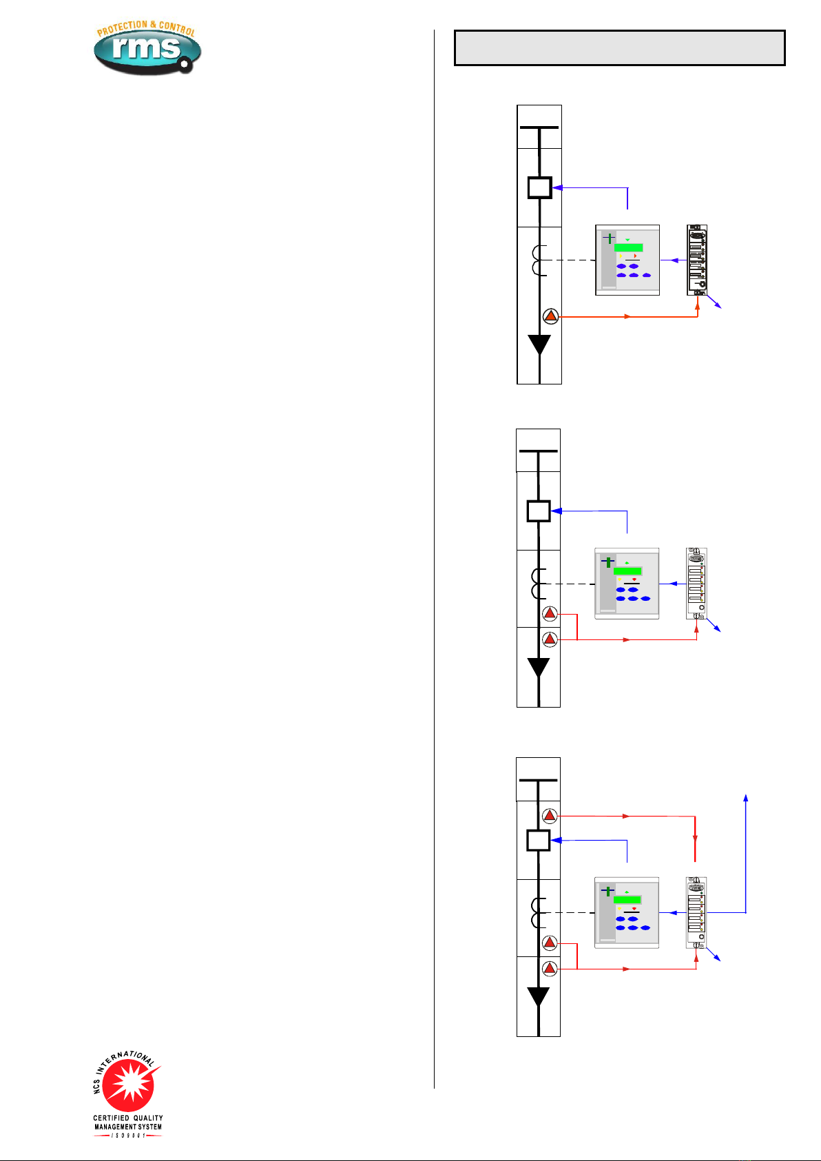
The 1S25 Arc Fault Monitor provides four (4) independent
tripping zones with one or two arc sensors per zone as depicted
in the single line application diagrams at right.
Figures 1 & 2 depict arc protection of up to four feeder circuits
with a single 1S25 as independent zones. A trip signal will be
initiated to the circuit breaker in the event of an arc fault occurring
at the sensor(s) within its zone provided the overcurrent relay
starter contact is picked up. In these applications the overcurrent
check stage is optional as the consequence of a single feeder
outage is less than the loss of an entire BUS.
Figure 3 shows an application where a 1S25 is applied for the
protection of the Cable box, CT chamber & CB chamber across
two feeder circuits (Zones). In this configuration one arc trip zone
is used to trip the feeder circuit breaker in the event of an arc
fault in the cable box or CT chamber. The second zone trip
output is wired to trip the upstream BUS breaker (BUS
overcurrent check not shown), in the event of an arc fault in the
CB chamber.
EXISTING SWITCHGEAR APPLICATIONS
The existing overcurrent relay protecting the feeder will normally
provide an independent output contact associated with the start
current setting of the relay. That is an output contact that will
close when a phase or earth fault current is detected above the
threshold which starts the internal relay timers. This starter
element should be set for instantaneous operation so that it will
pick up in the order of 15ms.
An Arc Fault Monitor relay 1S25 is installed on the switchgear
panel adjacent to the protection relay.
1S30 optical arc sensors are fitted in the cable termination box &
CT chamber as depicted in figure 2.
The overcurrent relay starter contact may optionally be wired in
series with the arc fault detection trip output contact as depicted
in figure 8. The resulting “AND” function trip output is wired to trip
the breaker in ~15ms in the event that an arc fault is detected
while the overcurrent start element is picked up.
The common arc trip & fail alarm contacts may be employed for
interface to a SCADA system for fault reporting.
NEW SWITCHGEAR APPLICATIONS
For new switchgear installations a modern numeric feeder
protection relay is likely to be employed which will have
numerous programming & configuration options.
The basic concept is the same as for the existing switchgear
application described above except that the additional features &
flexibility of modern feeder protection relay allows improved
system integration.
This may be achieved by using the common arc trip output
contact to interface to a programmable status input on the feeder
protection relay. Depending on the model of protection relay
being used this input may be programmed to provide an alarm
message on the HMI, time stamped event record available via its
communications link.
Switchgear Applications
ZONE 1
ARC PROTECTION
COMMON
ALARM
OUTPUT
1S2550/51
Figure 1: Single arc sensor per zone 1 - Cable box
ZONE 1
ARC PROTECTION
COMMON
ALARM
OUTPUT
1S2550/51
HEALTH Y
ZONE 2
ZONE 3
ZONE 4
ZONE 1
Custom text
Custom text
Custom text
Custom text
FAIL
FAIL
FAIL
FAIL
TRIP
TRIP
TRIP
TRIP
RESET
/TES T
Figure 2: Two arc sensors per zone - Cable box & CT chamber
ZONE 1
ARC PROTECTION
COMMON
ALARM
OUTPUT
1S2550/51
HEALTH Y
ZONE 2
ZONE 3
ZONE 4
ZONE 1
Custom text
Custom text
Custom text
Custom text
FAIL
FAIL
FAIL
FAIL
TRIP
TRIP
TRIP
TRIP
RESET
/TES T
ZONE 2 TRIP
UP STREAM
BREAKER
ZONE 2
ARC PROTECTION
ZONE 1 TRIP
Figure 3: Two arc sensors in zone 1 - Cable box & CT chamber
One or two arc sensors in zone 2 for CB chamber

Visit www.rmspl.com.au for the latest product information.
Due to RMS continuous product improvement policy this information is subject to change without notice. 1S25/Issue F/07/03/2011 - 3/9
COMBINED BUS BAR & SWITCHGEAR ARC PROTECTION
Figure 4 shows an application where a single 1S25 is applied for
the protection of a feeder Cable box & CT chamber plus the CB
chamber & BUS chamber using up to eight arc sensors over four
zones. In this configuration one arc trip output is used to trip the
feeder circuit breaker in the event of an arc fault in the cable box
/ CT chamber. Zone 2, 3 & 4 trip outputs are used to trip the BUS
breaker (BUS overcurrent check stage not shown), in the event of
an arc fault in the CB chamber or BUS chamber.
ZONE 1
ZONE 2
ARC PROTECTION
ZONE 3
ARC PROTECTION
ZONE 2, 3 & 4 TRIP
UP STREAM BREAKER
ZONE 4
ARC PROTECTION
COMMON ALARM OUTPUT
1S25
HEALTH Y
ZONE 2
ZONE 3
ZONE 4
ZONE 1
Custom text
Custom text
Custom text
Custom text
FAIL
FAIL
FAIL
FAIL
TRIP
TRIP
TRIP
TRIP
RESET
/TES T
50/51
Figure 4: Two arc sensors in zone 1 - Cable box & CT chamber
One or two arc sensors in zone 2 for CB chamber
One or two arc sensors in zone 3 for BUS chamber
One or two arc sensors in zone 4 for BUS chamber
BUS Bar Applications
BUS BAR ARC PROTECTION
Figure 5 depicts how the 1S25 may also be applied for the
protection of bus bars. The number of sensors in the bus
chamber is dictated by the switchgear design and the length of
switchboard.
In most indoor metal clad switchgear the bus bar chamber is a
continuous chamber between panels only broken into segregated
sections at a bus section breaker & as such the strategic
placement of one or two arc sensors in each bus bar chamber
run is normally adequate.
Some indoor metal clad switchgear may segregate the bus
chamber of each panel from the next via insulated bus chamber
side barriers per panel, if this is the case then each bus chamber
per panel would need to be monitored by at least one arc sensor.
Isolating switches between BUS bar sections need also be
considered & appropriate tripping zones created to ensure
isolation of the faulted section.
In large enclosures the arc sensors should be placed at
approximately 5m intervals. 1S30 arc sensors are also available
with dual optical detectors to allow detection of arc in both
directions.
ZONE 1 & 3
TRIP COMMON
ALARM
OUTPUT
50/51 1S25
HEALTH Y
ZONE 2
ZONE 3
ZONE 4
ZONE 1
Custom text
Custom text
Custom text
Custom text
FAIL
FAIL
FAIL
FAIL
TRIP
TRIP
TRIP
TRIP
RESET
/TES T
ZONE 2 & 3
TRIP
50/51
ZONE 1
TRIP
ZONE 3
TRIP
ZONE 2
TRIP
ZONE 3
TRIP
ZONE 1 ZONE 3 ZONE 2
ZONE 1
TRIP
ZONE 2
TRIP
Figure 5: One to eight arc sensors located in the BUS chamber in up to four tripping zones

Visit www.rmspl.com.au for the latest product information.
Due to RMS continuous product improvement policy this information is subject to change without notice. 1S25/Issue F/07/03/2011 - 4/9
ZONE 1
ARC PROTECTION
COMMON
ALARM
OUTPUT
1S2550/51
HEALTH Y
ZONE 2
ZONE 3
ZONE 4
ZONE 1
Custom text
Custom text
Custom text
Custom text
FAIL
FAIL
FAIL
FAIL
TRIP
TRIP
TRIP
TRIP
RESET
/TES T
TRIP
Figure 6:
Up to eight arc sensors distributed in low voltage switchgear.
Over current check stage depicted.
Low Voltage Applications
LOW VOLTAGE ARC PROTECTION
Figures 6 & 7 depict how the 1S25 may also be applied for low
voltage panels & MCC switchgear.
Figure 6 depicts an arrangement where over current check stage
is employed while the protection application depicted in figure 7
is a system based solely on arc detection.
1S25
HEALTH Y
ZONE 2
ZONE 3
ZONE 4
ZONE 1
Custom text
Custom text
Custom text
Custom text
FAIL
FAIL
FAIL
FAIL
TRIP
TRIP
TRIP
TRIP
RESET
/TES T
COMMON
TRIP ALARM
OUTPUTS
Figure 7:
Up to eight arc sensors distributed in low voltage switchgear or
MCC compartments without over current check
Visit www.rmspl.com.au for the latest product information.
Due to RMS continuous product improvement policy this information is subject to change without notice. 1S25/Issue F/07/03/2011 - 5/9
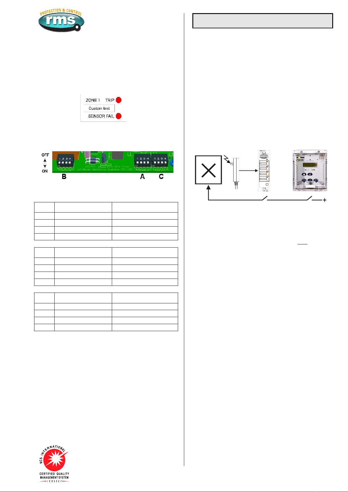
OPERATION INDICATOR
Two (2) LED’s are provided for each tripping zone to provide the
following status indications:
Trip: Flashes for 2s on detection of arc fault in zone & then solid
Resets when front panel reset button pressed or voltage
pulse applied to remote status input.
Fail: Flashes to indicate failure of 1S30 Arc Fault Sensor in zone.
CONFIGURATION SWITCHES
Three banks (A, B & C), of four (4) configuration switches are
accessible to the user by first withdrawing the relay module from
the outer case.
CONFIGURATION SWITCH SETTINGS
The internal wiring label identifies the position of the following
switch functions as follows:
Switch
ON
OFF
A1
Zone 1 Arc sensor fitted
Zone 1 Arc sensor not fitted
A2
Zone 2 Arc sensor fitted
Zone 2 Arc sensor not fitted
A3
Zone 3 Arc sensor fitted
Zone 3 Arc sensor not fitted
A4
Zone 4 Arc sensor fitted
Zone 4 Arc sensor not fitted
Switch
ON
OFF
B1
Zone 1 – 2 Arc sensors
Zone 1 – 1 Arc sensor
B2
Zone 2 – 2 Arc sensors
Zone 2 – 1 Arc sensor
B3
Zone 3 – 2 Arc sensors
Zone 3 -1 Arc sensor
B4
Zone 4 – 2 Arc sensors
Zone 4 – 1 Arc sensor
Switch
ON
OFF
C1
Latching trip contacts
Self reset trip contacts
C2
Independent trip outputs
Common trip outputs
C3
Apply volts to BLOCK
Remove volts to BLOCK
C4
DC only status inputs
AC/DC status inputs
ARC SENSOR CIRCUIT SUPERVISION
The 1S30 Arc Sensor is the heart of the system & supervision of
circuit continuity is critical for correct operation. To monitor the
integrity of the wiring between the 1S30 arc sensor & 1S25 Arc
Monitor, a continuous 2mA supervision current flows between the
units.
The 1S25 alarm contact will drop out after a 1s time delay if it
fails to detect this current.
The failed zone will be indicated by the front panel ‘Sensor fail’
LED.
Operation
ARC SENSOR FUNCTION
The 1S30 is an optical sensor that responds to the flash of light
emitted during the incidence of an arcing fault. Onset of the light
flash & detection by the 1S30 occurs in a few ms.
When an arc is detected, the resistance presented by the 1S30
drops to a level where the current flow increases to approximately
20mA. This increased current flow is instantaneously detected by
the 1S25 & its trip output contacts closed. Refer to the 1S30
Technical Bulletin for further details.
ARC FAULT TRIPPING USING CURRENT CHECK
Fast operation of a tripping scheme usually results in reduced
system security. The arc detection method can however,
combine the 1S25 optical detection technique with a traditional
overcurrent method to maximize system security particularly for
BUS bar protection schemes. Both conditions must coexist for
the trip condition to be met as depicted in figure 8.
ARC FAULT TRIP INITIATE
CB ARC FAULT
MONITORSENSOR
OVER-CURRENT RELAY
3 Pole OC + EF
HEALTHY
ZONE 2
ZONE 3
ZONE 4
ZONE 1
Custom text
Custom text
Custom text
Custom text
FAIL
FAIL
FAIL
FAIL
TRIP
TRIP
TRIP
TRIP
RESET
/TEST
Figure 8:
Key components required to implement an Arc Fault Protection
scheme with an overcurrent check stage
to enhance system security
The application examples in figures 1 to 5 utilize this concept for
enhanced system security in that both the 1S25 AND the OC 50
starter contact must be picked up for a CB trip signal to be
initiated. As the arc fault trip contact picks up considerably faster
than the overcurrent relay starter element, the CB trip time will be
dictated by the overcurrent relay performance.
LOW CURRENT ARCING FAULTS
Arcing faults can occur at low current levels & it is possible for
the over-current starter element to be set above this level. To
avoid this problem & obtain very fast clearance (<10ms), of an
arc fault, the 1S25 arc fault trip contact may be wired directly to
the breaker operate coil. It should be noted that this method may
lead to reduced system security.
ARC DETECTION RESET TIME (Effect of multiple arc trips)
A delay of 2s is required to reset the 1S25 after an initial arc
sensor trip. Subsequent arc detection will cause the trip output
contacts to re-operate.
INDEPENDENT TRIP OUTPUT CONTACTS
The 1S25 provides up to four (4) tripping zones each with an
independent tripping output. Alternatively configuration switch C2
can be set to OFF so that all trip outputs will operate in the event
of an arc being detected by any sensor.
ARC SENSOR CONTINUOSLY PICKED UP
High ambient light levels may cause a 1S30 to be continuously
picked up. This condition could occur for example if the CB cable
box cover was left open in very high ambient light level
conditions. A non arc fault over-current pick up would then result
in an arc fault trip operation.
To avoid possible mal operation due to this condition, the 1S25 is
designed to automatically disable the arc fault tripping function if
the 1S30 sensor is picked up for >10s. The 1S25 alarm contact
will be set & the front sensor fail LED will flash until the ambient
light level problem is corrected. The 1S25 will then perform an
arc sensor test function & automatically reset.
The failed zone will be indicated by the front panel ‘Sensor fail’
LED.

Visit www.rmspl.com.au for the latest product information.
Due to RMS continuous product improvement policy this information is subject to change without notice. 1S25/Issue F/07/03/2011 - 6/9
AUXILIARY SUPPLY
A high efficiency switchmode power supply is incorporated which
provides a low burden to the auxiliary supply.
Low range model: 20-70V DC
High range model: 40-300V DC & 40-275V AC
AUXILIARY SUPPLY BURDEN (At 110V DC)
Quiescent: Less than 4W
Maximum: Less than 10W
OPERATING TIME OF ARC FAULT DETECTION
Arc fault trip contacts guaranteed to pick up in less than 10ms
including bounce. Typical operate time is 7ms.
Reset time of the arc fault element is 2s.
CRO trace showing nominal operation time of the trip contacts at
7ms. First contact touch at 6.25ms and fully closed by 7.25ms.
Operation in <10ms is considered acceptable as current check
relay operate time is ~15ms.
FRONT PANEL LED’s
Green system healthy LED
Arc Trip - One red LED per zone – off, flashing or on solid
Sensor Alarm – One red LED per zone – off, flashing or solid
ARC FAULT BLOCK STATUS INPUT DELAY
AC Rejection Filter
Initiate input
Minimum
ON
OFF
P/U
<16ms
<4ms
DC
D/O
<4ms
<16ms
P/U
<23ms
AC
D/O
N/A
<33ms
Table 1
STATUS INPUT OPERATING VOLTAGE
An internal configuration switch is provided to select status input
operation for DC only or AC/DC. This setting may be pre defined
when ordering.
18 - 300V DC Set Configuration Switch to ON
In this mode the universal status input will reject AC signals that
may be induced on the control wiring. Suitable for high security
applications where a DC battery supply is available.
18 - 300V DC & 18 – 275V AC Set Configuration Switch to OFF
In this mode the universal status input is designed to operate on
both AC & DC input voltages. Suitable for applications where an
AC auxiliary voltage is available such as transformer or generator
control panels.
STATUS INPUT MINIMUM OPERATING CURRENT
10mA P/U for 1ms then reducing to1.5mA after 4ms.
RESET
Press the front reset button or pulse the reset status input.
Technical Data
OUTPUT CONTACTS
Tripping contacts: 8 - 2 N/O per tripping zone
Common tripping contact: 1 N/O
Fail alarm: 1 C/O contact for the power supply /
CPU fail / arc fault sensor.
Normally picked up & drops out to
signal an alarm condition.
OUTPUT CONTACT RATINGS IEC60255-0-2
Carry continuously
5A AC or DC
0.5s 20A AC or DC
Make & carry
L/R ≤ 40ms & V ≤ 300V
0.2s 30A AC or DC
AC resistive
AC inductive
1,250VA
250VA @ PF ≤ 0.4
DC resistive
75W
Break capacity
I ≤ 5A & V ≤ 300V
30W @ L/R ≤ 40ms
DC inductive
50W @ L/R ≤ 10ms
Minimum number of operations
106 at maximum load
Minimum recommended load
0.5W limit 10mA / 5V
TRANSIENT OVERVOLTAGE IEC60255-5
Between all terminals & earth
5kV 1.2/50us 0.5J
Between circuit groups:
Status/Reset Inputs, Auxiliary Supply,
Sensor Inputs, Trip Outputs
Without damage or flashover
5kV 1.2/50us 0.5J
INSULATION COORDINATION IEC60255-5
Between all terminals & earth
2.0kV RMS for 1 minute
Between circuit groups:
Status/Reset Inputs, Auxiliary Supply,
Sensor Inputs, Trip Outputs
2.0kV RMS for 1 minute
Across normally open contacts
1.0kV RMS for 1 minute
AUXILIARY SUPPLY IEC60255-11
Allowable breaks / dips in supply
Collapse to zero from nominal voltage
≤ 20ms
HIGH FREQUENCY DISTURBANCE IEC60255-22-1 CLASS III
2.5kV 1MHz common mode
1.0kV 1MHz differential mode
No mal operation
ELECTROSTATIC DISCHARGE IEC60255-22-2 CLASS III
6kV contact discharge
No mal operation
RADIO FREQUENCY INTERFERENCE IEC60255-22-3
10V/m, 80 TO 2,700MHz
No mal operation
FAST TRANSIENT IEC60255-22-4
4kV, 5/50ns, 100KHz repetitive
No mal operation
CONDUCTED RFI IEC60255-22-6
10V, 0.15 to 80MHz
No mal operation
CUSTOM ALARM TEXT - Refer ordering information page.
Maximum characters: 2 lines x 15 characters / tripping zone.
Maximum font size: 1 line x 10 characters / tripping zone.
TEMPERATURE RANGE IEC68-2-1/2
Operating: -5 to +55oC
Storage: -25 to +75oC
HUMIDITY IEC68-2-78
40 oC & 95% RH non condensing
Visit www.rmspl.com.au for the latest product information.
Due to RMS continuous product improvement policy this information is subject to change without notice. 1S25/Issue F/07/03/2011 - 7/9
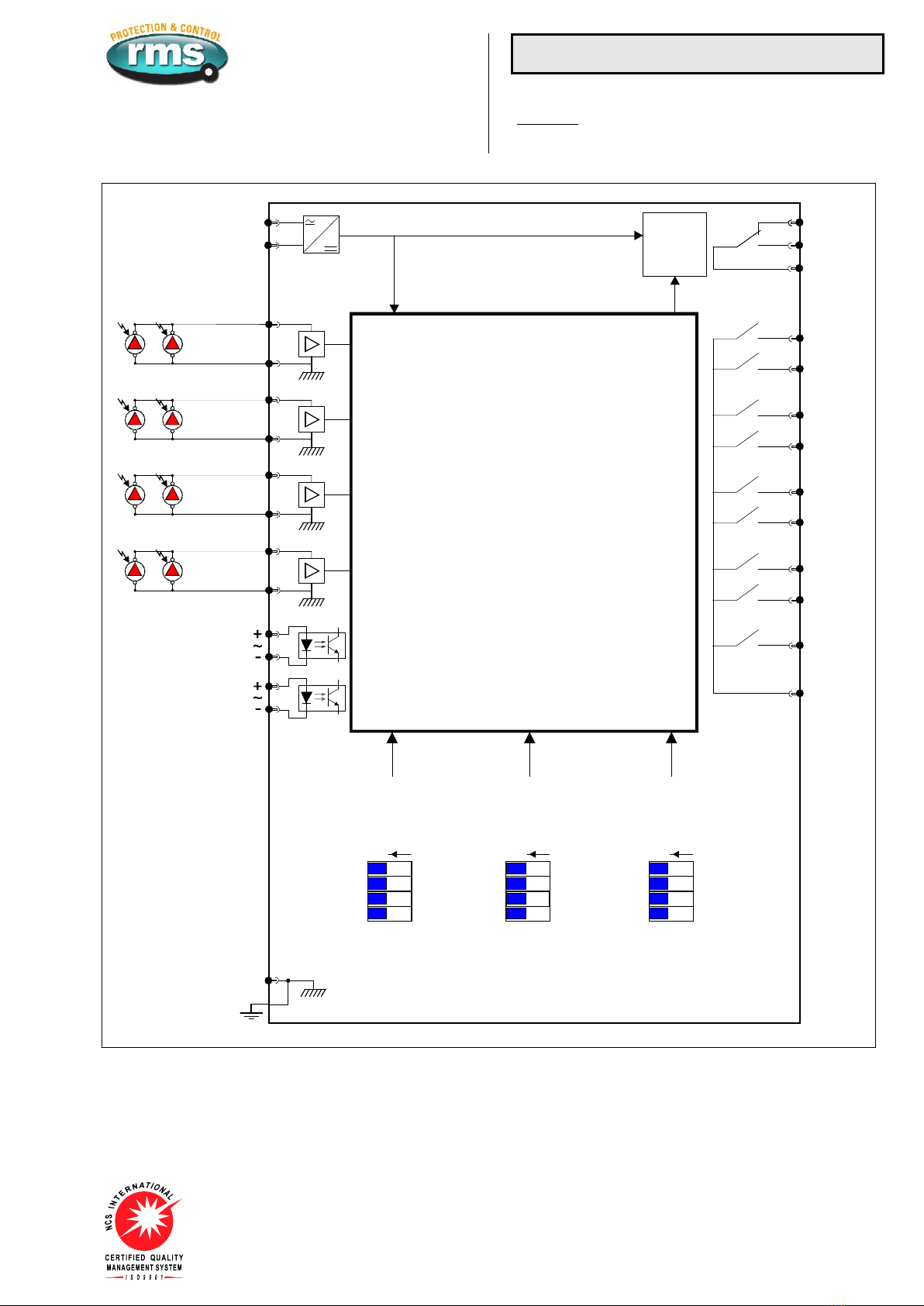
Wiring
TERMINATION SCREWS
M4 Screws
An M4 screw kit is supplied as standard with each 1S25.
Additional M4 screw kits may be purchased separately.
1
24
5
26
28
3
Vx Power supply,
CPU & sensor
fail alarm
Remote reset
Arc fault BLOCK input
Configuration switches
(Primary PCB)
7
9
11
13
15
17
19
21
Zone 1
Arc sensor input
1S30
Arc Fault Sensors
Zone 2
Arc sensor input
Zone 3
Arc sensor input
Zone 4
Arc sensor input
6
8
Zone 1 Trip
Zone 1 Trip
Zone 2 Trip
Zone 2 Trip
4Common Trip
Switch 1
Switch 2
Switch 3
Switch 4
BANK
A
BANK
B
BANK
C
27
25
23
Fail
Healthy
Alarm common
Signal processing
and logic
functions
ON ON ON
Arc sensor fault signal
Zone 3 Trip
Zone 3 Trip
Zone 4 Trip
Zone 4 Trip
12
10
16
14
20
18
22 Common
2
Case & module
earth connection
Figure 9: Wiring diagram for 1S25 four zone arc fault monitor - Relays shown in de-energized condition

Visit www.rmspl.com.au for the latest product information.
Due to RMS continuous product improvement policy this information is subject to change without notice. 1S25/Issue F/07/03/2011 - 8/9
HEALTHY
ZONE 2
ZONE 3
ZONE 4
ZONE 1
Custom text 1
Custom text 2
Custom text 3
Custom text 4
SENSOR FAIL
SENSOR FAIL
SENSOR FAIL
SENSOR FAIL
TRIP
TRIP
TRIP
TRIP
RESET
/TEST
P
R
O
T
E
C
T
I
O
N
&
C
O
N
T
R
O
L
Figure 10: Alarm text position layout
Case Mounting
CASE
2M28-S draw out case
ACCESSORIES SUPPLIED WITH EACH RELAY
1 x M4 self threading mounting screw kit P/N 290-406-151
2 x M4 terminal screw kit (28 per kit) P/N 290-407-153
1 x Product Test Manual
1S30 ARC FAULT SENSORS
Refer to the 1S30 Technical Bulletin for details.
Figure 11: 1S30 Arc Fault Sensors
Through panel mounting detector version depicted at left
Front panel view of dual detector version depicted at right
Front view
15 2 holes of 3.7
Indicative
position
Side view
Size 2M28-S
draw out case
Drawing units: mm
Terminal layout Panel cut out
Suits flush panel mounting &
4U high 19 inch rack frame
14
1 2
27 28
Figure 12: Case mounting details 8 point alarm version

Visit www.rmspl.com.au for the latest product information.
Due to RMS continuous product improvement policy this information is subject to change without notice. 1S25/Issue F/07/03/2011 - 9/9
ALARM TEXT LABELS
The 1S25 front panel has provision for custom text to identify the
sensor location for each arc fault tripping zone. The required text
may be engraved on the front panel by the factory if specified at
time of order. Alternatively the front panel may be removed for
engraving by the user or contractor. The RMS web site provides
an ACAD file for this purpose.
The front panel is fabricated from flexible plastic sheet with a
white surface & black substrate to provide high contrast black
text when engraved.
Removal of the front label is achieved by drawing out the 1S25
module from the outer case & pulling the label from the edges at
the mid point between the top & bottom draw out handles. This
will cause the label to bend & disengage from the top & bottom
handle retention points. Once free from the 1S25 module the
front label can be placed on an engraving table. Additional factory
engraved labels may be sourced from RMS for later field
installation.
While an engraved label provides the most permanent record
other methods such as laser printed stick on labels or indelible
marker pen may be satisfactorily employed.
CUSTOM ENGRAVED TEXT DEFINITION
Complete the following tables with one character per box. Refer
to the front panel layout depicted in figure 10. Submit completed
labeling information with the 1S25 product ordering code. For
maximum font size limit text for each alarm point to 1 line x 10
characters.
Text will be left justified.
Zone 1
Zone 2
Zone 3
Zone 4
Ordering Information
ORDER CODE
The order code determines the production build in the factory &
cannot be changed in the field.
Generate the required order code as follows: e.g. 1S25 BA
Order
Code
General
Type
1
2
1S25
-
1
AUXILIARY SUPPLY RANGE
A 20 - 70V DC
B 40 - 300V DC & 40 – 275V AC
2
CUSTOM ENGRAVED TEXT
A Not required No engraving - factory default
B Required Complete the custom text details at left
CONFIGURATION CODE (Optional specification)
The configuration code can be set in the field by withdrawing the
relay module & following the instructions on the side plate label.
The configuration code may be specified at time of order so that
the relay will be shipped from the factory pre-set to meet
customer requirements. e.g. CONFIG-0101-0101-1111
If a configuration code is not specified the factory default will be
set as indicated below. i.e. CONFIG-1111-1111-1111
Configuration
Switches
Specify
Factory
Configuration
A1
A2
A3
A4
CONFIG
-
B1
B2
B3
B4
-
C1
C2
C3
C4
-
A1-4
ZONE 1 - 4 SENSOR INPUTS
1 ON Arc sensor(s) connected (Default)
0 OFF No sensor connected
B1-4
ZONE 1 - 4 SECOND SENSOR
1 ON Second sensor connected (Default)
0 OFF Single sensor only
C1
OUTPUT CONTACTS FUNCTION
1 ON Latching (Default)
0 OFF Self reset
C2
OUTPUT CONTACTS GROUPING
1 ON Segregated zone tripping outputs (Default)
0 OFF Common outputs
C3
ARC FAULT INITIATE INPUT FUNCTION
1 ON Apply volts to BLOCK arc detection (Default)
0 OFF Remove volts to BLOCK arc detection
C4
STATUS INPUT AC REJECTION
1 ON DC operation only - AC rejection ON (Default)
0 OFF AC / DC operation - AC rejection OFF
© 2011 Relay Monitoring Systems Pty Ltd
Due to RMS continuous product improvement policy this information is subject to change without notice.
Australian Content
Unless otherwise stated the product(s) quoted
are manufactured by RMS at our production
facility in Melbourne Australia. Approximately
60% of our sales volume is derived from
equipment manufactured in house with a local
content close to 80%. Imported components
such as semi-conductors are sourced from local
suppliers & preference is given for reasonable
stock holding to support our build requirements.
Quality Assurance
RMS holds NCSI (NATA Certification Services
International), registration number 6869 for the
certification of a quality assurance system to
AS/NZS ISO9001-2008. Quality plans for all
products involve 100% inspection and testing
carried out before despatch. Further details on
specific test plans, quality policy & procedures
may be found in section A4 of the RMS product
catalogue.
Product Packaging
Protection relays are supplied in secure
individual packing cardboard boxes with moulded
styrene inserts suitable for recycling. Each
product & packing box is labeled with the product
part number, customer name & order details.
Design References
The products & components produced by RMS
are based on many years of field experience
since Relays Pty Ltd was formed in 1955. A large
population of equipment is in service throughout
Australia, New Zealand, South Africa & South
East Asia attesting to this fact. Specific product &
customer reference sites may be provided on
application.
Product Warranty
All utility grade protection & auxiliary relay
products, unless otherwise stated, are warranted
for a period of 24 months from shipment for
materials & labour on a return to factory basis.
Repair of products damaged through poor
application or circumstances outside the product
ratings will be carried out at the customer’s
expense.
Standard Conditions of Sale
Unless otherwise agreed RMS Standard Terms &
Conditions (QF 907) shall apply to all sales.
These are available on request or from our web
site.
Relay Monitoring Systems Pty Ltd
6 Anzed Court, Mulgrave, Victoria 3170, AUSTRALIA
Table of contents


