RNG Kraus Group MICON 500C User manual

MICON 500C
ELECTRONIC SEQUENCING COMPUTER
INSTALLATION MANUAL:
NORTH AMERICAN AND EUROPEAN
TM
TM
1999 Kraus Group Inc., Publication Number 234AY00.INS R06
Printed in Canada


i
TABLE OF CONTENTS
1.0 SERVICE AND PRODUCT SUPPORT - CANADA…………………………………………….………………………..1
2.0 PRE-INSTALLATION CHECK……………………………………………………………………………………………. 2
3.0 PHYSICAL MOUNTING CONSIDERATIONS……………………………………….…………………………………. 5
3.1 HANDLE SWITCH COUPLING……...……………..…………………………………………………………… 6
3.2 HANDLE SHAFT ACTUATION……………………..……………………………………………………………8
4.0 CUSTOMER HARNESS LEAD ELECTRICAL CONNECTIONS……………………………………………….….…10
4.1 IMPORTANT WARNINGS……………………….……………….……….……………..…………………….. 10
4.2 WIRING DETAIL – NORTH AMERICAN……..………………………………………..………………………11
4.2.1 FIGURE 11 - WIRING DIAGRAM – NORTH AMERICAN.………………….12
4.3 WIRING DETAIL - EUROPEAN ………………………………………...……………..………………………13
4.3.1 FIGURE 12 - WIRING DIAGRAM – EUROPEAN…..………………………..14
4.4 COMMUNICATION INTERFACE CONNECTIONS………..……...……………..…………………………. 15
5.0 POST INSTALLATION CHECK………………………………………………………..……………………………..….16
6.0 MICON 500C OPERATION……………….……………………………………….……………..………………………17
6.1 CONSOLE ACCESSING FOR PRICE CHANGING: MCIU…………………………………………………17
6.2 MICON 500C COMMUNICATOR OPERATION…..………………………………………………………….18
6.2.1 READING TOTALIZERS ON A SINGLE TIER DISPENSER…………….……………………….18
6.2.2 SETTING PRICES ON A SINGLE TIER DISPENSER…………………………….………………19
6.2.3 READING CURRENT PRODUCT FLOW RATE, TEMPERATURE AND PRESSURE………..20
6.3 TWO TIER PRICE OPERATION………………….……………………………………..……………………..21
6.3.1 TWO TIER OPTION INSTALLATION……………………………………..…………………………21
6.3.2 SETTING PRICES ON A TWO TIER DISPENSER……………………..…………………………22
6.3.3 MAKING DISCOUNT PRICE SALES ON A TWO TIER DISPENSER..………………………… 22
6.3.4 READING TOTALIZERS ON A TWO TIER DISPENSER..……………………………………….23
6.4 ELECTRONIC AUDIT TRAILS……………………………………………………..…………………….……. 24

ii
TABLE OF CONTENTS (CONT’D)
7.0 MICON 500C SEQUENCING………………….…………………………………..……………………………………..25
7.1 DEFINITIONS – INFO-PAC SEQUENCING SETTINGS…………...……………..…………………………26
7.1.1 MIN FLOW (minimum flow)………………..…………………….……………………………………26
7.1.2 MAX FLOW (maximum flow)………………..…………………….…………………………………..27
7.1.3 IPTP FLOW 1 (increased pressure trip point – flow 1)……….………………………………….…27
7.1.4 IPTP FLOW 2 (increased pressure trip point – flow 2)……….…………………………………….27
7.1.5 FILL OPTION………………..…………………….………………………………….………………..27
7.1.5.1 FILL OPTION 1…………………………..………………………………………………….28
7.1.5.2 FILL OPTION 2…………………………..………………………………………………….29
8.0 PFS 3000 / 3600 PRESSURE-TEMPERATURE COMPENSATION SYSTEM…………………………………….32
8.1 GENERAL DESCRIPTION………………………………..…………...……………..…………………………32
8.2 HARDWARE……………….………………………………..…………...……………..……………………….. 33
8.2.1 HARDWARE INPUTS…………………………..……………………………………………………..33
8.3 SOFTWARE……………….………………………………..…………...……………..…………………………34
8.4 END-OF-FILL DETERMINANTS………………………..…………...……………..…………………………..35
8.5 RESTART TIMEOUT AND NOISE BLANKING………..…………...……………..………………………….35
8.6 EXCESS FLOW / EXCESS FILL………………………..…………...……………..…………………………. 36
8.7 OPTIONAL PARAMETERS………………………..…………...……………..………………………………..37
8.8 FAILURE PROTECTIONS………..…………...……………..…………………………………………………38
8.9 SYSTEM REDUNDANCIES………………………..…………...……………..………………………………. 39
8.10 ALARMS………………………..…………...……………..…………………………………………………….. 39
9.0 MICON 500C FAULT CODES………………………..…………...……………..………………………………………40
TABLES
1. ACCESSORY / OPTIONAL PARTS - KRAUS ……………..…………………..…………………………….. 5
2. MICON 500C WIRING DETAIL (NORTH AMERICAN)…..…………………..………………………………11
3. MICON 500C WIRING DETAIL (EUROPEAN).……………..…………………..…………………………….13
4. COMMUNICATIONS INTERFACE CONNECTIONS FOR THE MICON 500CN
(NORTH AMERICAN)……………………………………………………………………………………………15
5. COMMUNICATIONS INTERFACE CONNECTIONS FOR THE MICON 500CE
(EUROPEAN)…………………………………………………………………………………………………..…15
6. M500 INFO-PAC PROGRAMMABLE FEATURES (FOR CNG); SOFTWARE VERSION 3.0 .…………25
7. M500C INFO-PAC PROGRAMMABLE FEATURES (FOR CNG); SOFTWARE VERSION 3.0 ………. 26

iii
TABLE OF CONTENTS: TABLES (CONT’D)
8. WIRE CONNECTIONS – FILL OPTION 1 ……..……………………………………………………………..28
9. WIRE CONNECTIONS – FILL OPTION 2 ……..……………………………………………………………..29
10. PFS 3000 / 3600 SYSTEM HARDWARE INPUTS ……..……………………………………………………33
11. ABSOLUTE PRESSURE ……..…………………………………………………………………………………34
12. ALARM SHUTDOWN TRIGGERS AND RESET ACTIONS ……..………………………………………….40
13. MICON 500C FAULT CODES ……..…………………………………………………………………………...41
14. SUMMARY OF FAULT CLEARING ACTIONS ……..………………………………………………………...42
FIGURES
1. BATTERY OFF ACTUATOR SHAFT POSITION……………………………………………………………... 2
2. COUPLER ASSEMBLY HANDLE OFF POSITION…………………………………………….……………...2
3. INFO-PAC AND CONFIGURATION EVENT COUNTERS ON THE MICON 500C………………………...3
4. RECEIVING DATA FROM MICON 500C………..………..…………….………………………………………4
5. “RECEIVED MICON” INFO-PAC DISPLAY………..………..…………….……………………………………5
6. STANDARD ACTUATOR SHAFT AND COUPLER ASSEMBLY POSITION..…………………………….. 6
7. INTRINSICALLY SAFE TWO PIN PLUG………..……………………………………..……………………….7
8. CUSTOMER LEAD EXIT…………………….……………..…………………………………………….………7
9. ACTUATOR SHAFT AND COUPLER ASSEMBLY POSITION FOR CLOCKWISE ROTATION…………8
10. HANDLE SHAFT ACTUATION FOR CLOCKWISE ROTATION ……………………..………….…………..9
11. WIRING DIAGRAM – NORTH AMERICAN ……………………..………….…………………………………12
12. WIRING DIAGRAM – EUROPEAN………. ……………………..………….…………………………………14
13. PRICE SETTING USING THE MICON COMMUNICATOR…..………….………………………………….16
14. DISPLAY DOLLAR AND VOLUME TOTALS…………..…………….……………………………………….18
15. PRICE SETTING USING THE MICON COMMUNICATOR…………..………….…………….……………19
16. READING TOTALIZERS……….……………………..…………….…………………………………………. 24
17. FILL OPTION 1…………..…………….………………………………………………………………………... 29
18. FILL OPTION 2………………………………..…………….…………………………………………………... 31
19. FAULT CODE IN PRICE DISPLAY……………………..………….…………………………………………. 40

MICON 500C Electronic Sequencing 1234AY00.INS R06
Computer Installation Guide
1.0 SERVICE AND PRODUCT SUPPORT - CANADA
Should you experience any difficulties in system operation, customer assistance is available.
The procedure to receive such assistance is as follows:
1. Document the following information:
§system dysfunction
§corrective measures taken
§system model number
§system serial number
§purchase order information
§date of installation
§equipment location (i.e., city, address, etc.)
2. Call or Fax our Product Service line at:
One of our qualified personnel will provide assistance in getting your system operational.
company service number:
1-204-988-1234
company fax number: 1-204-654-2881
KRAUS GROUP INC. assumes no liability or responsibility whatsoever pertaining to the accuracy or
currency of the information supplied in this manual. Installation of MICON 500C electronic pumpheads
in every case is the sole responsibility of the installer performing the work. Kraus Group Inc. assumes
no liability or responsibility whatsoever resulting from any type of installation, operation or configuration,
whether performed properly, improperly or in any other way. The information supplied herein is a guide
only.
MICON 500 is a registered trademark of Kraus Group Inc.
MICON 500C Electronic Sequencing 2234AY00.INS R06
Computer Installation Guide
2.0 PRE-INSTALLATION CHECK
The MICON 500C is an electronic pumphead designed for use with compressed natural gas
(CNG) dispensers.
After carefully unpacking the MICON 500C, inspect for shipping damage. Refer to the options label(s)
on the MICON 500C shipping box(es) to ensure the MICON 500C is properly configured for the
intended application. A preliminary electrical check should be performed as follows:
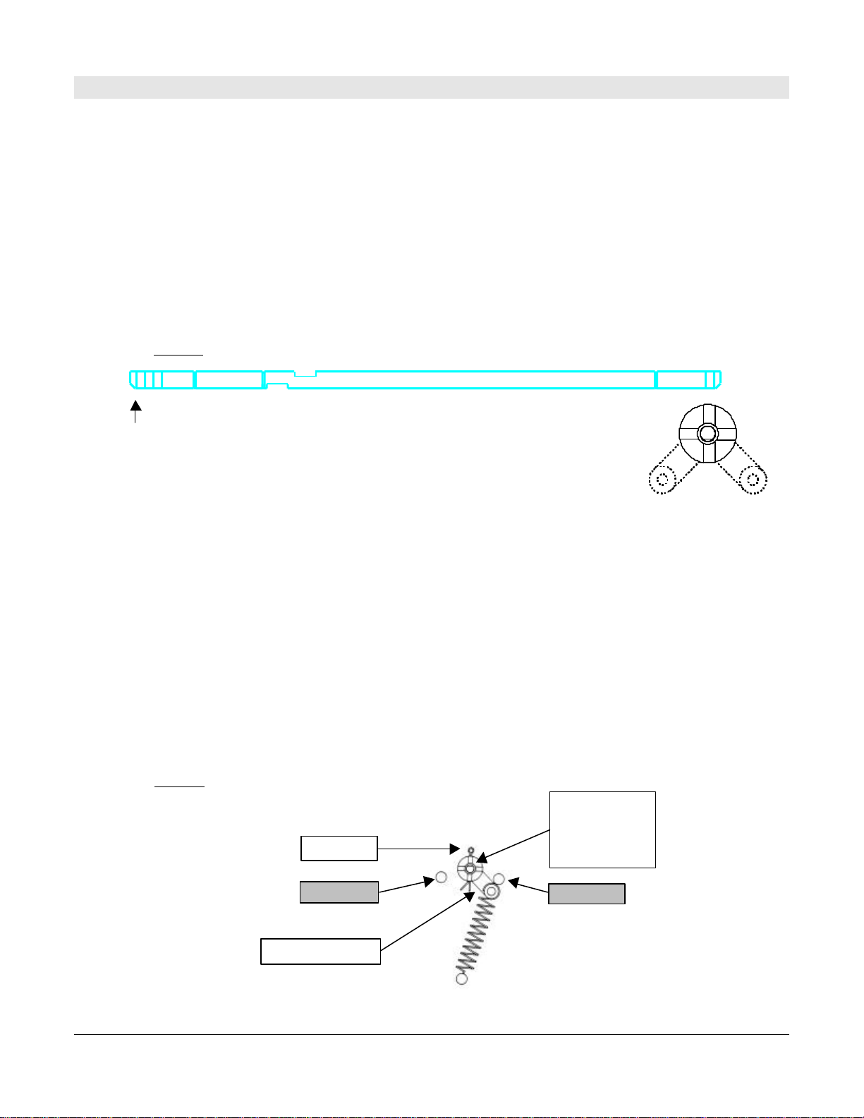
1. Observe position of the pump handle. The MICON 500C is normally shipped with the
actuator shaft in the OFF position: flat (beveled) surface on the end of the shaft facing
DOWN. Current drain will be negligible, however, if unit shipped with battery ON.
2. Battery is ON whenever flat (beveled) side of shaft is facing any direction except DOWN.
Battery should be ON with flat (beveled) side of shaft facing UP when handle OFF.
Prepare handle switch for a preliminary check by positioning shaft and coupler assembly in
handle OFF position:
a) Pull cotter pin.
b) Rotate actuator shaft until the flat (beveled) side faces UP.
c) Rotate the coupler assembly until it snaps against the opposite stop pin.
d) Re-install cotter pin in a vertical position.
The handle OFF coupler assembly will appear as in Figure 2 below. Coupler assembly may
rest against stop pin #1 or stop pin #2, as long as cotter pin is vertical and flat (beveled) side
of shaft faces UP when handle OFF.
battery
OFF
when flat (beveled) side of shaft facing
DOWN
FIGURE 1 – BATTERY OFF ACTUATOR SHAFT POSITION
FIGURE 2 – COUPLER ASSEMBLY HANDLEOFF POSITION
COUPLER ASSEMBLY
STOP PIN #1
STOP PIN #2
COTTER PIN
ACTUATOR SHAFT
FLAT (BEVELED)
SIDE UP IS HANDLE
OFF (BATTERY ON)
POSITION

MICON 500C Electronic Sequencing 3234AY00.INS R06
Computer Installation Guide
2.0 PRE-INSTALLATION CHECK (CONT’D)
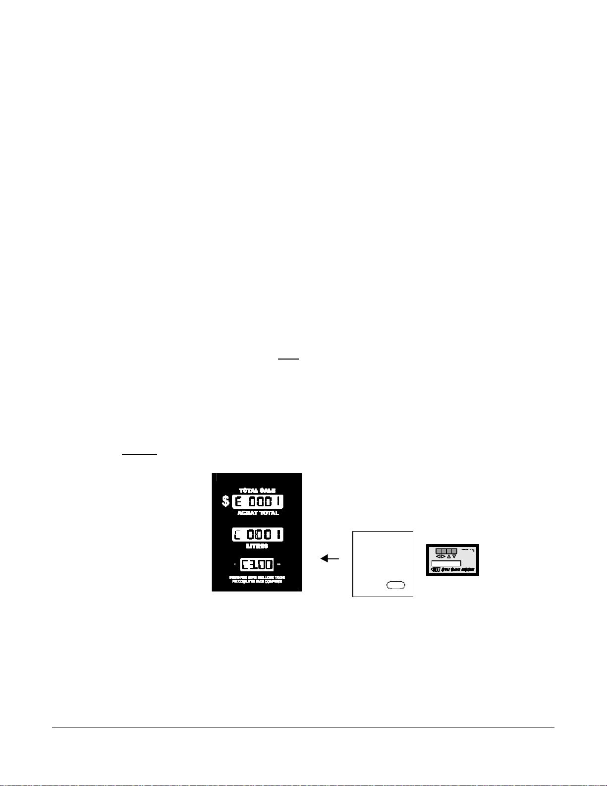
3. The MICON 500C digital display can be manually triggered to display configuration event
counters data in the dollar and volume displays, followed by the software version number in
the price display. To do this:
ØFlip the handle switch rapidly ON, then OFF. The display will show the configuration
event counters in the dollar and volume displays, and the software version in the price
display.
ØThe event counter in the dollar display indicates the number of times settings have
been changed in “MICON” mode (metrological configuration parameters) with the INFO-
PAC.
ØThe event counter in the volume display indicates the number of times the settings
have changed in the “m500C” mode of the INFO-PAC.
configuration event counter in
dollar display
:
Indicates number of times settings have been changed in m500 mode (“micon”
mode) with the INFO-PAC. m500 mode is used to control liquid fuel flow in
earlier INFO-PAC models, and certain CNG fuel flow features in INFO-PAC
version 3.0 and later software.
configuration event counter in volume display:
Indicates number of times settings have changed in “m500c” Info-Pac mode.
m500c mode is used to configure MICON heads used to dispense CNG.
software version number in
price display
INFO-PAC model M500C is designed to configure MICON 500C pump
computer heads used to control flow of CNG product (compressed natural
gas) from dispensers.
The INFO-PAC is a transmitter and receiver. Programmable pumphead
features can be set up in the INFO-PAC memory, then transmitted to MICON
heads. The INFO-PAC also receives and displays features already
programmed to MICON pumpheads.
MICON 500C Display
INFO-PAC
FIGURE 3 – INFO-PAC AND CONFIGURATION EVENT COUNTERS ON THE MICON 500C
MICON 500C Electronic Sequencing 4234AY00.INS R06
Computer Installation Guide
2.0 PRE-INSTALLATION CHECK (CONT’D)
4. Figure 3 (preceding page) indicates both counters (dollar and volume) are set to 0001. To
check the current configuration of your MICON 500C, use the INFO-PAC receive functions,
described in the INFO-PAC m500C Programming Manual, and outlined in steps a) to d)
below:
The RX MICON (m500) setting on the INFO-PAC is designed to receive MICON 500C
settings from units which have already been programmed.
To receive information from the MICON 500C:
a) Go to breaker box and turn power OFF. Caution: Ensure breaker box does not feed
power to equipment which should remain ON.
The MICON 500C display should be flashing. If display is blank, unit is in sleep (i.e.,
battery save) mode. To correct this, turn handle ON and OFF. Display will start
flashing.
b) Turn INFO-PAC m500C ON by pressing left arrow key. Using up or down arrow key,
scroll to INFO-PAC RX MICON option. Set RX MICON on by pressing left or right
pointing arrow key.
c) Take INFO-PAC and go to the front display of the MICON 500C electronic pumphead.
Locate optical sensor (oval “hole”) at right of price display on MICON 500C.
Aim INFO-PAC receiver / transmitter (located behind red tinted filter at centre edge of
INFO-PAC at MICON 500C optical sensor.
Red LED to left of MICON 500C price display flashes as INFO-PAC receives data from
MICON 500C.
INFO-PAC
MICON 500C
electronic
pumphead display
Aim top
of
INFO-PAC
(red
window) at
optical
sensor
ON
FIGURE 4 – RECEIVING DATA FROM MICON 500C

MICON 500C Electronic Sequencing 5234AY00.INS R06
Computer Installation Guide
TABLE 1 – ACCESSORY / OPTIONAL PARTS - KRAUS
2.0 PRE-INSTALLATION CHECK (CONT’D)
d) When INFO-PAC has received a copy of the MICON 500C setup information correctly,
INFO-PAC display will show “Received Micon”. To view each setting, scroll with the up
or down arrow key. (Default settings are summarized in Table 6 and 7, pages 25, 26.)
4. Enter a price. See section 6.2.2 – Setting Prices, page 19 for a description of the
procedure. Price reading is also described in section 6.2.1 – Reading Totalizers, page 18.
Setting prices and reading totalizers on two tier dispensers is described on pages 22 and
23, sections 6.3.3 and 6.3.4.
For a detailed explanation of INFO-PAC operation, see INFO-PAC MICON 500C Programming
Manual.
If any faults are detected during this preliminary check, consult your factory or service
representative.
3.0 PHYSICAL MOUNTING CONSIDERATIONS
Kraus Group Inc. is presently offering accessory parts to facilitate the field installation of the MICON
500C into various dispensers. These accessory parts, listed in Table 1 below, must be ordered
separately. Consult your service representative.
PART NO. ACCESSORY / OPTIONAL PARTS - KRAUS
W392 2-TIER SWITCH HARNESS
W199 RESISTIVE TEMPERATURE PROBE
Y101 KEY SWITCH
PWP 320 PUSH BUTTON SWITCH (PRICING)
DS 18 HANDLE LINK UNIT
247KT00 MCIU CONTROL BOX
MC 200D COMMUNICATOR (HAND HELD)
FIGURE 5 – “RECEIVED MICON” INFO-PAC DISPLAY

MICON 500C Electronic Sequencing 6234AY00.INS R06
Computer Installation Guide
3.1 HANDLE SWITCH COUPLING
1. The handle switch coupling on the side of the MICON 500C must be connected to the
dispenser handle. In most installations, the dispenser handle can be coupled directly to the
MICON 500C. The MICON 500C handle switch can be turned to the ON position by rotating
the actuator shaft 90 degrees in either a clockwise or counterclockwise direction. The
direction of rotation is dependent upon the position of the dispenser handle in relation to the
coupler.
To verify correct placement of the actuator, the flat (beveled) side of the shaft should
be in the battery ON position when the dispenser handle is OFF. This will be flat side
UP (battery actually is ON in any position except flat side DOWN).
battery
ON
when flat (beveled)side ofshaft facing
UP
FIGURE 6 – STANDARD ACTUATOR SHAFT AND COUPLER ASSEMBLY POSITION
COUPLER ASSEMBLY
STOP PIN #1
STOP PIN #2
COTTER PIN
ACTUATOR SHAFT
FLAT (BEVELED)
SIDE UP IS HANDLE
OFF (BATTERY ON)
POSITION
THE COUPLER ASSEMBLY SHOWN REQUIRES
A 90 DEGREE CLOCKWISE ROTATION TO TURN
ON (I.E., COTTER PIN TO THE RIGHT).
IF COUPLER ASSEMBLY RESTS AGAINST STOP
PIN #1 WHEN HANDLE OFF, ASSEMBLY WOULD
REQUIRE 90 DEGREE COUNTERCLOCKWISE
ROTATION TO TURN ON (I.E., COTTER PIN TO
THE LEFT).
HANDLE IS ON WHEN FLAT SIDE IS TOWARD
EITHER LEFT OR RIGHT SIDE
BATTERY IS ACTUALLY ON WHENEVER FLAT
(BEVELED) SIDE OF SHAFT IS FACING ANY
DIRECTION EXCEPT DOWN.

MICON 500C Electronic Sequencing 7234AY00.INS R06
Computer Installation Guide
FIGURE 7
INTRINSICALLY
SAFE 2 PIN PLUG
FIGURE 8
CUSTOMER LEAD EXIT
3.1 HANDLE SWITCH COUPLING (CONT’D)
2. If desired, a normally open handle switch can be connected to the intrinsically safe 2 pin
plug. In this case, the actuating shaft need not be connected and should be left in the
Handle OFF position.
3. Customer lead exit, located on the top of the explosion-proof housing, must be connected to
a suitable junction box with rigid conduit (North American only). A seal fitting must be in-
stalled between the MICON 500C and the junction box, and must be within 18” of the
MICON 500C.
North America:
connect rigid conduit
at customer lead exit.
intrinsically safe 2 pin plug
located in MICON 500C tub
Handle OFF
whenflat
(beveled) side
of actuator
shaftfacing
UP.

MICON 500C Electronic Sequencing 8234AY00.INS R06
Computer Installation Guide
FIGURE 9
ACTUATOR SHAFT AND COUPLER ASSEMBLY POSITION
FOR COUNTERCLOCKWISE ROTATION
3.2 HANDLE SHAFT ACTUATION
As outlined in explanation accompanying Figure 6, page 6, the MICON 500C handle switch may be
switched ON by rotating the actuator shaft 90 degrees in either direction. As shipped from the factory,
a clockwise rotation of the coupler assembly (as viewed from the coupler side) is required to switch the
pumphead ON.
If the installation requires a counterclockwise rotation to turn the head ON, see
Figure 9 below and complete the following steps:
a) Turn the coupler assembly to the desired handle OFF position (i.e., against stop pin #1).
b) Remove the cotter pin which secures the coupler assembly to the actuator shaft.
c) Rotate the actuating shaft until the flat (beveled) surface on the end is facing upwards, and
re-install the cotter pin in a vertical position.
THE COUPLER ASSEMBLY SHOWN IS RESTING AGAINST STOP PIN #1 WHEN IN
HANDLE OFF (BATTERY ON) POSITION, AND REQUIRES A 180 DEGREE
CLOCKWISE ROTATION TO TURN ON (I.E., COTTER PIN TO THE LEFT).
FLAT (BEVELLED) END OF ACTUATOR SHAFT IS FACING UP WHEN HANDLE
OFF AND SNAPS TO NEGATIVE 90 DEGREE ANGLEWHEN HANDLE ON AND
BATTERY ON.
COUPLER ASSEMBLY
STOP PIN #1
STOP PIN #2
ACTUATOR SHAFT
FLAT (BEVELLED)
SIDE UP IS HANDLE
OFF (BATTERY ON)
POSITION
ON
COTTER PIN

MICON 500C Electronic Sequencing 9234AY00.INS R06
Computer Installation Guide
FIGURE 10
HANDLE SHAFT ACTUATION
FOR CLOCKWISE ROTATION
3.2 HANDLE SHAFT ACTUATION (CONT’D)
Remove cotter pin from coupler
assembly after turning the
assembly to the desired OFF
position.
Rotate actuating shaft until flat side of
actuator shaft faces UP when handle OFF,
then re-install cotter pin.
MICON 500C Electronic Sequencing 10 234AY00.INS R06
Computer Installation Guide
4.0 CUSTOMER HARNESS LEAD ELECTRICAL CONNECTIONS
4.1 IMPORTANT WARNINGS
!!! IMPORTANT – PLEASE READ !!!
All wiring must be installed in accordance with national and local electrical
codes.
Substitution of components may impair intrinsic safety.
When this unit is used in retail trade in Canada, Measurement Canada, an
agency of Industry Canada, must be notified of the installation or servicing
of this unit. This unit is subject to inspection upon installation and at such
other times as the regulations may state.
WARNING
ATTENTION
When performing installation or maintenance work of any kind,
including servicing MICON 500C electronic pumphead main boards or
using the INFO-PAC to program pumpheads, it is the responsibility of
the service person performing the work to ensure:
1. All power to MICON pumphead(s) is turned OFF.
2. All supply of gas to dispenser(s) being serviced is shut OFF.
CAUTION
KRAUS GROUP INC. assumes no responsibility for personal injury or equipment damage caused by non-
observance of safety warnings, or non-compliance with national or international legal regulatory
requirements.

MICON 500C Electronic Sequencing 11 234AY00.INS R06
Computer Installation Guide
4.2 WIRING DETAIL - NORTH AMERICAN
Table 2: MICON 500C Wiring Detail (North American) Reference: Drawing #5789-8, page 12
Wire # 120 VAC Lines - (Wire #3a, #3b, #7, #8 are 14 AWG. All other wires are 18 AWG.)
1 (BLK) 120 VAC head power hot line. If power is interrupted on this line, the head will go into standby
and power-fail modes.
2 (WHT) Neutral for head power and main board authorize/authorize request circuit.
3A & 3B (GRN) Earth. These lines are connected internally to the casting and must be connected to the
service ground.
7 (BLK) 120 VAC Sequencing Power
8 (ORN) Sequencing Output #1
14 (BRN) Authorize Input. Application of 120 VAC will “authorize” the MICON 500C to dispense product.
When the handle switch is turned ON, the MICON 500C applies a 2.7 KΩcapacitive
reactance between this line and wire #2 to serve as an authorize request load for Kraus Group
Inc. Self-Serve equipment. External equipment may be used to provide an authorization
signal to the Micon 500LN Electronic Register provided that both units are controlled through a
common circuit breaker.
15 (GRY) Authorize Output. When 120 VAC is applied to wire #14 and the handle switch is ON, 120
VAC will be present on this line. (3 Amp. maximum load)
21 (WHT/GRN) Sequencing Output #2
22 (WHT/YEL) Sequencing Output #3
23 (WHT/ORN) Sequencing Output #4
24 (WHT/RED) Sequencing Output #5
Wire # Low Voltage Lines
4 (YEL) Money Pulser Positive. This line is normally connected to the pulser power supply positive
line (+30 volts maximum, DC only) and provides power to the money pulser line.
5 (RED) Money Pulser Negative (output). The MICON 500C will source a maximum of 100 mA from
the money pulser positive (#4) to this line to form a pulse once for each penny of product dis-
pensed. (Used with KRAUS MONITOR and MICRO consoles.)
12 (YEL/RED) LAG Pulser Input Positive. This line is connected through a 680 Ωresistor to the anode of an
optocoupler LED.
13 (YEL/BRN) LEAD Pulser Input Positive. This line is connected through a 680 Ωresistor to the anode of an
optocoupler LED.
18 (BLU) Volume Pulser Negative (output). This line provides a pulse (as described above for money
pulser) for each specified fraction of a unit of volume. (Used for card or key systems.)
19 (WHT/BLU) Volume Pulser Positive. This line is normally connected to the pulser power supply positive
line (+30 volts maximum, DC only) and provides power to the volume pulser line.
25 (PUR) Gas Temperature Input 4-20mA.
26 (BLK/WHT) Pulser Input Negative. This line is connected to the LED cathodes. Input voltage range for the
pulser input wires 12 & 13 is 5-20 VDC.
Wire # Data Communications Lines
9 (PNK) Talk-To-Pump. This line is connected to the appropriate terminal on the “TTP” terminal block
of a Concept 5000 control box or MCIU* or to the diode board of a Micro 2RP system, and
carries messages from the console to the dispenser.
10 (TAN) Talk-To-Console. This line is connected to the “TTC” terminal block of a Concept 5000 control
box or MCIU and carries messages from the dispenser to the console.
16 (GRN) Data Channel Common. This line is connected to the “DCC” terminal block of a Concept 5000
control box or MCIU* or to the diode board of a Micro 2RP system.
17 (WHT/BRN) RS-422 Positive Input.
* Separate installation manual (247AY00.INS R00 – North American) is available with all Kraus Group Inc. MCIU’s
(Micon Communication Interface Units). See Table 4, page 15 of this manual for summary of communications
interface connections.
MICON 500C Electronic Sequencing 12 234AY00.INS R06
Computer Installation Guide
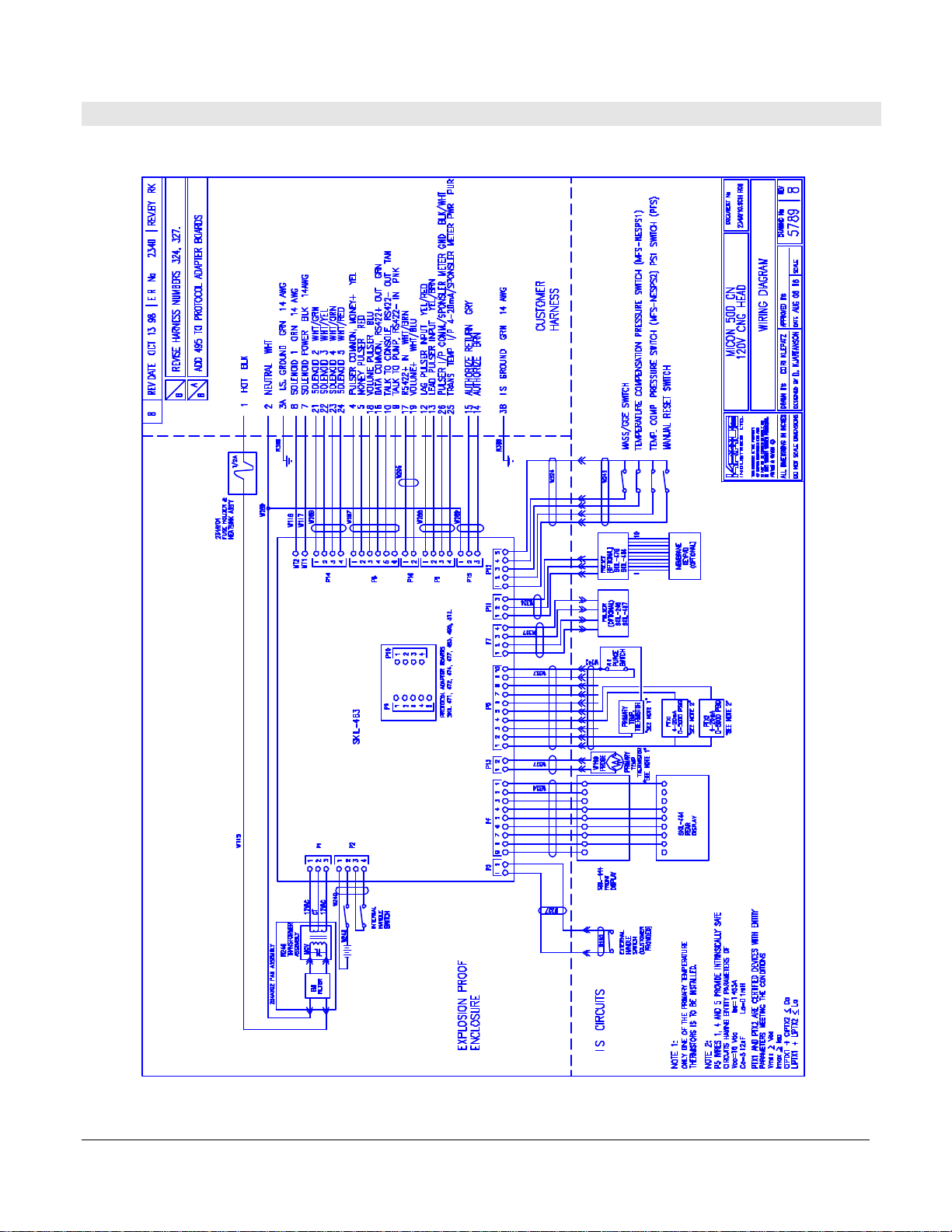
4.2.1 FIGURE 11 – WIRING DIAGRAM – NORTH AMERICAN

MICON 500C Electronic Sequencing 13 234AY00.INS R06
Computer Installation Guide
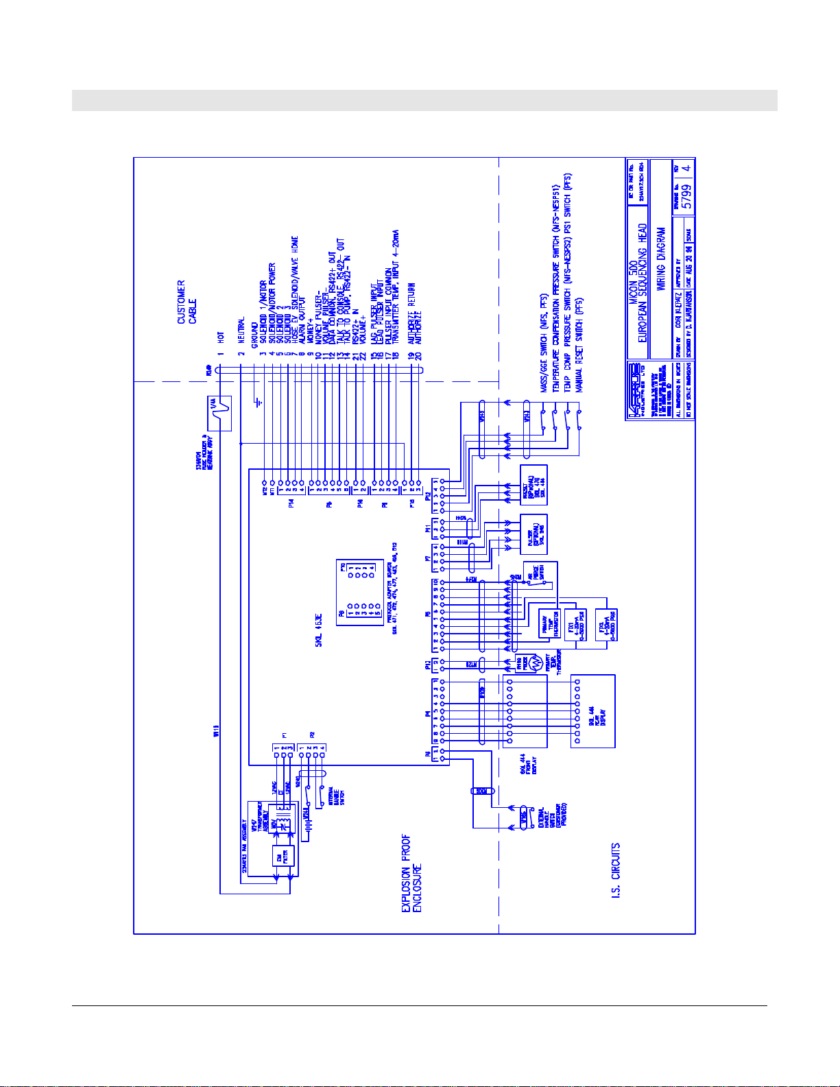
4.3 WIRING DETAIL - EUROPEAN
Table 3: MICON 500C Wiring Detail (European) Reference: Drawing #5799-4, page 14
Wire # 230 VAC Lines - (metric type 24 conductor shielded cable)
YEL/GRN Earth. This line is connected internally to the casting and must be connected to the service ground.
1230 VAC head power hot line. If power is interrupted on this line, the head will go into standby and
power-fail modes.
2Neutral for head power and main board authorize/authorize request circuit.
3Sequencing Output #1
4230 VAC Sequencing Power
5Sequencing Output #2
6Sequencing Output #3
7Hose Evacuation Solenoid/Valve Home
8Alarm Output
19 Authorize Output. When 230 VAC is applied to wire #20 and the handle switch is ON, 230 VAC will
be present on this line. (3 Amp. maximum load)
20 Authorize Input. Application of 230 VAC will “authorize” the MICON 500C to dispense product.
When the handle switch is turned ON, the MICON 500C applies a 14 KΩcapacitive reactance
between this line and wire #2 to serve as an authorize request load for Kraus Group Inc. Self-Serve
equipment. External equipment may be used to provide an authorization signal to the Micon
500LN Electronic Register provided that both units are controlled through a common circuit
breaker.
Wire # Low Voltage Lines
9Money Pulser Positive. This line is normally connected to the pulser power supply positive line (+30
volts maximum, DC only) and provides power to the money pulser line.
10 Money Pulser Negative (output). The MICON 500C will source a maximum of 100 mA from the
money pulser positive (#9) to this line to form a pulse once for each penny of product dispensed.
(Used with KRAUS MONITOR and MICRO consoles.)
11 Volume Pulser Negative (output). This line provides a pulse (as described above for money pulser)
for each specified fraction of a unit of volume. (Used for card or key systems.)
15 LAG Pulser Input Positive. This line is connected through a 680 Ωresistor to the anode of an
optocoupler LED.
16 LEAD Pulser Input Positive. This line is connected through a 680 Ωresistor to the anode of an
optocoupler LED.
17 Pulser Input Negative. This line is connected to the LED cathodes. Input voltage range for the
pulser input wires 15 & 16 is 5-20 VDC.
18 Gas Temperature Input 4-20mA.
22 Volume Pulser Positive. This line is normally connected to the pulser power supply positive line
(+30 volts maximum, DC only) and provides power to the volume pulser line.
Wire # Data Communications Lines
12 Data Channel Common. This line is connected to the “DCC” terminal block of a Concept 5000
control box or MCIU** or to the diode board of a Micro 2RP system.
13 Talk-To-Console. This line is connected to the “TTC” terminal block of a Concept 5000 control box
or MCIU** and carries messages from the dispenser to the console.
14 Talk-To-Pump. This line is connected to the appropriate terminal on the “TTP” terminal block of a
Concept 5000 control box or MCIU** or to the diode board of a Micro 2RP system and carries
messages from the console to the dispenser.
21 RS-422 Positive Input.
** Separate installation guide (247AY01.INS R00 – European) is available with all Kraus Group Inc. MCIU’s:
Micon Communication Interface Units. See Table 5, page 15 of this manual for summary of communications
interface connections.
MICON 500C Electronic Sequencing 14 234AY00.INS R06
Computer Installation Guide
4.3.1 FIGURE 12 - WIRING DIAGRAM - EUROPEAN
MICON 500C Electronic Sequencing 15 234AY00.INS R06
Computer Installation Guide
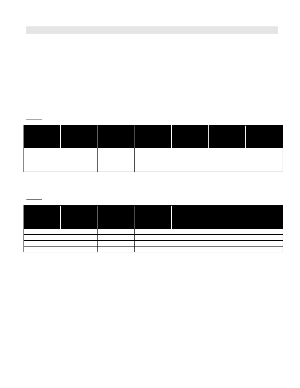
4.4 COMMUNICATION INTERFACE CONNECTIONS
Tables 4 and 5 below describe communication interface connections for the following interface options:
•Tokheim Interface
•Gilbarco Interface
•Tatsuno Interface
•RS-422 Interface
•RS-232 Interface
•Kraus MNET Interface
Customer
Harness Wire
#
Tokheim
Interface Gilbarco
2-Wire
Interface
Tatsuno
Interface RS-422
Interface RS-232
Interface Kraus MNET
Interface
16 DCC Not used Not used OUT “+” Gnd DCC
10 TTC 2-wire “+” “+” OUT “-” Tx TTC
9TTD 2-wire “-” “-” IN “-” Rx TTP
17 Not used Not used Not used IN “+” Not used Not used
Customer
Cable Wire # Tokheim
Interface Gilbarco
2-Wire
Interface
Tatsuno
Interface RS-422
Interface RS-232
Interface Kraus MNET
Interface
12 DCC Not used Not used OUT “+” Gnd DCC
13 TTC 2-wire “+” “+” OUT “-” Tx TTC
14 TTD 2-wire “-” “-” IN “-” Rx TTP
21 Not used Not used Not used IN “+” Not used Not used
TABLE 4 – COMMUNICATIONS INTERFACE CONNECTIONS FOR THE MICON 500CN (NORTH AMERICAN)
TABLE 5 – COMMUNICATIONS INTERFACE CONNECTIONS FOR THE MICON 500CE (EUROPEAN)
Table of contents


 Service guide")


