RNG KIT-STCS60D User manual

KIT-STCS60D | KIT-STCS100D
Solar Suitcase 60W and 100W Owner’s Manual
RNG Group Inc. (Renogy)
14288 Central Ave., Suite A Chino, CA 91710
1-800-330-8678

1
Product Description
The Renogy Solar Suitcases combine highly efficient Renogy Solar Panels and a fully adjustable 10
Amp PWM Fully Adjustable Solar Charge Controller with LCD Screen to create an easy-to-use,
‘plug and play’system.
This system is specifically designed for mobile off-grid applications, where space and weight
limitations are abundant. The Solar Suitcase 100W supports 12V deep cycle battery varieties such
as sealed lead acid, gel, and flooded. With built-in tilting stands, these panels can be adjusted at
different angles to maximize the power output throughout the seasons.
The alligator clips included in this package make it easy to connect the panel to a battery in
seconds. If one ever needs to connect a battery with a different type of end terminal, the alligator
clips are attached via MC4 Connectors.
PWM Technology
The built-in charge controller is based on advanced Pulse Width Modulation (PWM) charging
technology. With a charging range of 0-100%, it can charge a battery quickly and safely under any
condition of the solar photovoltaic system.
When charging, the controller utilizes automatic duty cycle conversion, creating pulses of current
to charge the battery. Intermissions make the oxygen and hydrogen generated by chemical
reactions combine again and become absorbed. This process can naturally eliminate both
concentration polarization and ohm polarization, and can also reduce the internal pressure of the
battery; thus, the battery will absorb more power. Pulse current charging mode allows the battery
more time to react, which reduces the gassing volume and makes the battery improve the
acceptance rate of the charging current.
To learn more about the 10A Amp PWM Charge Controller included with the Renogy Solar
Suitcase 100W, please visit our Guides and Downloads webpage, and download the separate
manual for this controller.
Scan the QR Code to visit the download page.
Or visit: http://goo.gl/NrqNn5

2
Components
Also included but not depicted:
Storage Case
10A PWM ViewStar LCD
Charge Controller
Junction box
Fuse Holder with
7.5A mini fuse
Battery Alligator
Clips
MC4
Connectors
Handle
Tilting Stands
15 ft. Tray
Cable
Latch
Aluminum frame with
corner protection
MC4 Connectors
Latch

3
Installation
1. Unclip the two latches on the side of the unit and unfold the two panels outward.
Extend the stands to support the solar panels.
2. The controller is mounted on metal plate. The plate is attached to the back of the panel
with Velcro. The hinges attached to the metal plate allow the user to swivel the charge
controller to get a better look at the LCD display. The Velcro allows the re-attachment of
the charge controller back under the panel.

4
3. Fully extend battery leads. Connect the red alligator clip to the positive (+) battery
terminal and the black alligator clip to the negative (-) battery terminal on a 12V battery.
Ensure that the connections are secure.
Note: The kit should be connected to a battery generating at least 9V to start the charge controller. If the
12V battery is fully discharged, charge it for a short period of time by other means to reach 9V.
4. When you connect the kit to the battery, the charge controller will display a boot up
message as follows:
Black
Red
WELCOME
VERSION 1.23

5
5. Adjusting Battery Size and Type: Press to enter to the options, press or
to navigate to the menu options.
When the inverse cursor rests on 5. Rated Value, press to enter into the nominal
parameter interface. Once again, press or to move between the adjustable
parameters. Pressing will move the inverse cursor to the right. While pressing
will move it to the left. If the inverse cursor is at the very beginning, press
to jump back to the main menu screen. When the inverse cursor rests at some parameter,
the contents of the parameter can be modified. To modify a parameter, press to
increase the current parameter, or press to reduce it. In this screen the battery
type and capacity can be modified. The battery capacity ranges from 1-999 AH.
After the last digit of the battery capacity, Press or to select the type of
battery.
Seal = Sealed Lead Acid (AGM), Gel = Gel Battery, Flood = Flooded (wet cell) battery
1.Monitoring .
2.Device Set
3.Parameter Set
4.Load Set
6
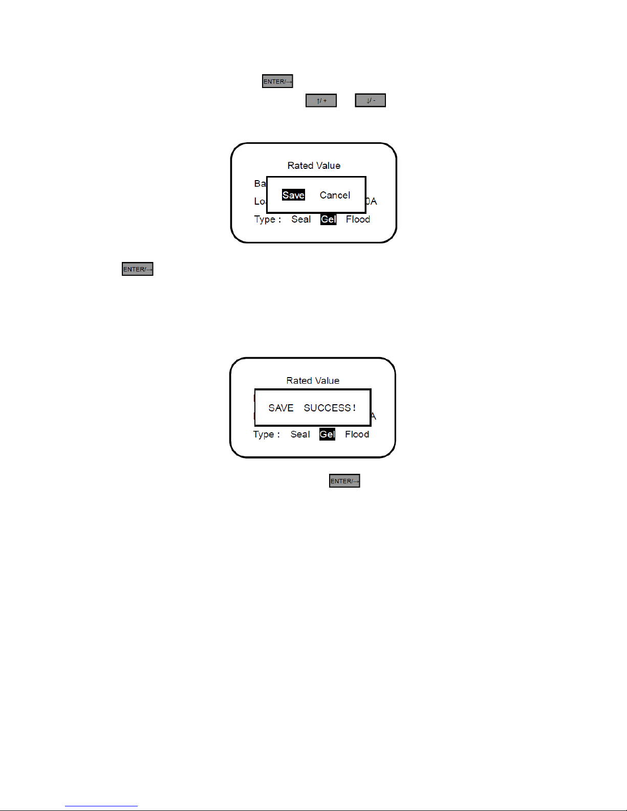
Settings can be saved by pressing until the last adjustable parameter is reached,
in this case will be the Battery Type. Press or to choose between Save or
Cancel. The inverse cursor will rest on the selected option.
Press to confirm the selection. If the Save option is chosen, then the parameters
will be saved. If Cancel was chosen, then parameters won’t be saved, and the screen will
jump back to the main menu interface. When saving, the controller will check and confirm
valid parameters. If the parameters are correctly set, and success message will appear as
shown below:
After successfully saving the parameters, press to exit to the main menu. The
controller should now have the correct parameters for the battery selected. If there is a
need to use different charging parameters, the controller is fully adjustable. Please refer
to the charge controller manual.
7
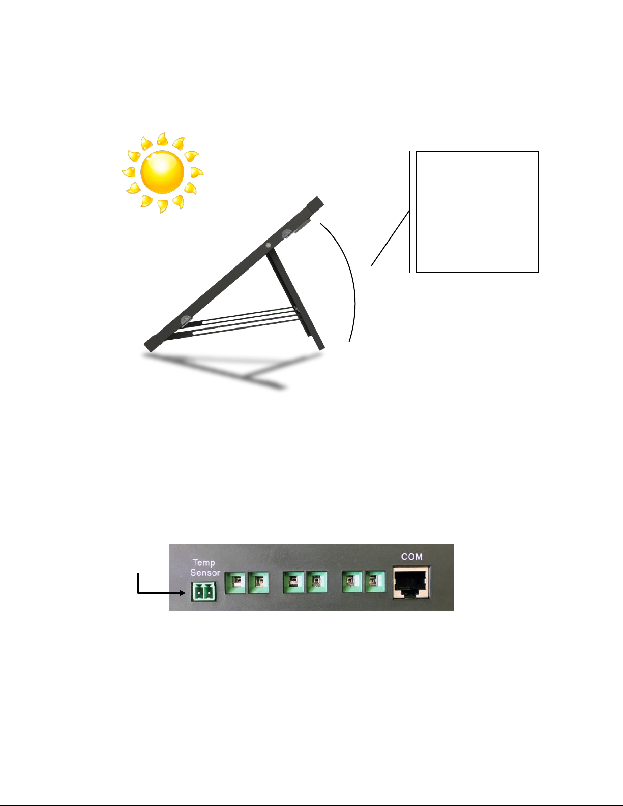
6. Find a clear sunlit area, free from overhanging tree branches, obstructions or shading.
The panel should be facing south, and the tilting angle should be adjusted as follows:
Note: To maximize the output, adjust the position of the kit regularly to track the sun movement
throughout the day
7. Remote Temperature Sensor (optional): The charge controller (ViewStar) has a built-
in temperature sensor. This is used for temperature compensation of the charging
parameters. During a hot summer day, the local temperature on the controller might
register a higher temperature than that from the battery if the battery is under shade.
For this reason, the controller also has a 2ERJ-3.81 port for a Remote Temperature
Sensor (Model: TS-R). The RTS can be placed next to the battery (ies). This optional
accessory can be purchased separately.
Summer
𝜃 = 𝐿𝑎𝑡𝑖𝑡𝑢𝑑𝑒 – 15°
Fall and Spring
𝜃 = 𝑎𝑡 𝑙𝑎𝑡𝑖𝑡𝑢𝑑𝑒
Winter
𝜃 = 𝐿𝑎𝑡𝑖𝑡𝑢𝑑𝑒 + 15°
𝜃
2ERJ-3.81
Port
8
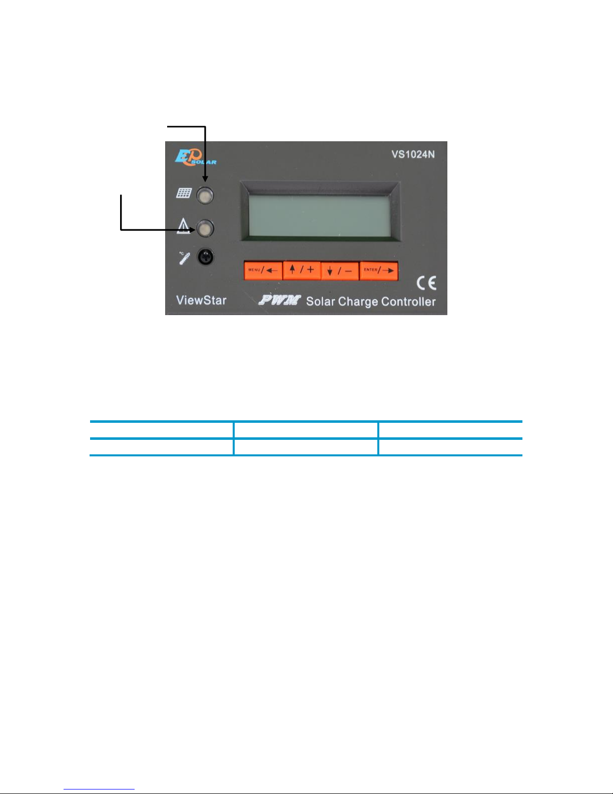
Charge Controller LEDs
Charging Indicator
The green LED indicator will turn on whenever sunlight is available for battery charging.
Under normal charging conditions, the green charging LED will stay on at all times.
Color
Indication
Operating State
Green
On solid
Charging
Table 1 Charging LED indicators
Fault Indicator
When the following cases occur the fault indicator will be flashing red:
Solar module
Over-current
Error while trying to measure the voltage
Reverse-protection MOS-I short
MOS-C short
MOS-I or MOS-C disconnection
MOS break in control section
Charging LED
Indicator
Fault
LED Indicator

9
Battery
Over-voltage
Error while trying to measure the voltage
The temperature is above range (battery too hot)
Load
Over load
Short
Discharging MOS Short
Error while trying to measure the voltage
Device
Controller is operating too hot
For trouble shooting please refer to the charge controller manual (Chapter 5).
Color
Indication
Operating State
Red
Flashing
PV: Over-current, Measure error,
MOS-I Short, MOS-C Short or MOS
Break
BATT: Over-voltage, Measure
error or Running too hot
LOAD: Over load, Short,
Discharging MOS short, or
Measure error
DEVICE: Running too hot
Table 2 Fault indicators

10
Frequently Asked Questions
Q. What type of batteries can be used with this kit?
A. Any sealed lead acid, gel, or flooded 12V battery (typically used in caravans,
motorhomes, boats etc.) is appropriate for use with this kit.
Q. Can this kit charge a 24V battery?
A. No, because this kit is designed to charge a 12V battery. Technically, it’s possible to
change solar panel connections to enable the kit to work in 24V mode; however, a
qualified, knowledgeable individual should only do this.
Note: unauthorized modification to 24V will void the warranty.
Q. Can the kit charge two or more 12V batteries connected in parallel?
A. Yes, it’s possible if the batteries have the same type and capacity and are wired in
parallel as a single 12V battery bank.
Q. Is there any risk that the solar kit will over charge my battery?
A. One of the functions of the solar charge controller is to ensure that your battery is not
over charged; therefore there is no risk of overcharge.
Q. Can I extend the battery leads?
A. Yes, it’s possible – please choose the same size of cable for extension. However, there
longer the extension, the greater the line loss. Bigger gauge will be required for longer
runs.
Q. Do I need to clean the solar panels?
A. Yes, it is recommended for better performance. Dust and dirt should first be swept off
the panel surface using a soft brush. When the sweeping is complete, use a wet cloth to
wipe the panel surface to remove remaining dirt and grime.
Q. Can rain damage the solar kit?
A. The solar panels are fully waterproof (IP66 class), the controller is not. We recommend
protecting the kit from rain, since water into controller may damage the internal circuitry.

11
Troubleshooting
Check all connections to ensure they are secure and clean
Check polarity of the battery connection and make sure the battery generates at
least 9V
Ensure the solar panels are exposed to sufficient light –ideally position them to
face the sun directly
For more information refer to the Troubleshooting section of the Solar Controller
Manual (skip anything which relates to load work in the controller manual as the
load terminals of the controller are not used)
Specifications
Solar Panels
Description
Parameter (60W)
Parameter (100W)
Maximum Power
60W
100W
Open Circuit Voltage (Voc)
21.6V
21.6V
Short Circuit Current (Isc)
3.62
6.17A
Maximum Power Voltage (Vmp)
18.0V
17.5V
Maximum Power Current (Imp)
3.34A
5.71A
Cell Type
Monocrystalline
Monocrystalline
Operating Temperature
−40°F to +185°F
−40°F to +185°F
Folded Size
13.60 x 25.40 x 2.80 “
19.88 x 27.17 x 2.36 “
Net Weight
21.20 lbs.
24.69 lbs.
Table 3 Solar panels specifications
Specifications under standard test conditions (STC): 1000W/m2, AM 1.5, 25 °C. Specifications are stated for
the solar panels only without the effect of the charge controller.
12
Charge Controller
Description
Parameter
Nominal System Voltage
12VDC
Rated Charge Current
10A
Rated Discharge Current
10A
Maximum Battery Voltage
32V
Max. Solar Input Voltage*
48VDC
Max. PV Input Power
120W (12V)
Self-consumption**
≤18mA
Charge Circuit Voltage Drop
≤ 0.24V
Discharge Circuit Voltage Drop
≤ 0.15V
Communication
TTL232 / 8 pin RJ45
Remote Temperature Sensor
2ERJ-3.81
Ground
Negative ground
Battery Type
Gel, Sealed (AGM), and Flooded
Table 4 Electrical Parameters
*Array voltage should never exceed maximum PV input voltage. Refer to the solar module documentation to
determine the highest expected array Voc (Open Circuit Voltage) as defined by the lowest expected ambient
temperature for the system location.
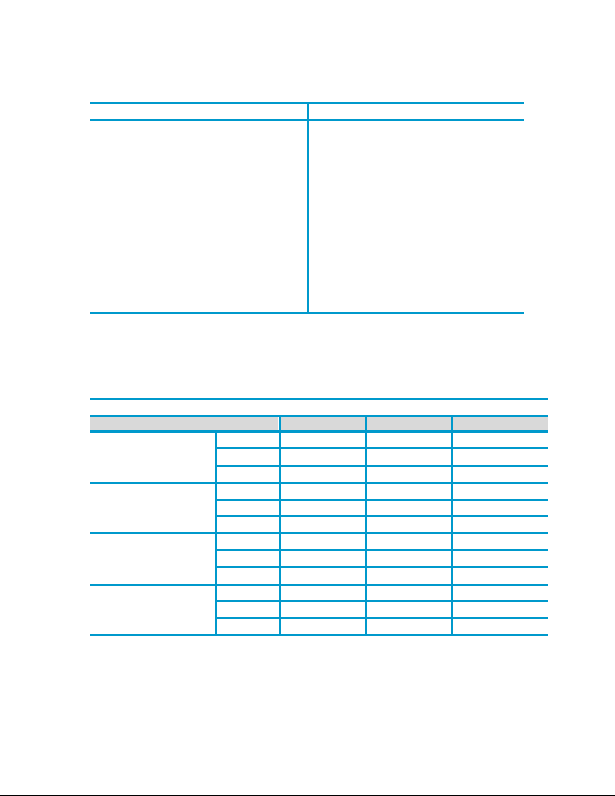
Charging Parameters
Table 5 Battery Parameters
Control Parameter
Battery type
Gel
Sealed
Flooded
High Volt Disconnect
Default
16.0V; x2/24V
16.0V; x2/24V
16.0V; x2/24V
Max
17.0V; x2/24V
17.0V; x2/24V
17.0V; x2/24V
Min
15.0V; x2/24V
15.0V; x2/24V
15.0V; x2/24V
Charging Limit Voltage
Default
15.5V; x2/24V
15.5V; x2/24V
15.5V; x2/24V
Max
16.0V; x2/24V
16.0V; x2/24V
16.0V; x2/24V
Min
14.0V; x2/24V
14.0V; x2/24V
14.0V; x2/24V
Over Voltage Reconnect
Default
15.0V; x2/24V
15.0V; x2/24V
15.0V; x2/24V
Max
16.0V; x2/24V
16.0V; x2/24V
16.0V; x2/24V
Min
14.0V; x2/24V
14.0V; x2/24V
14.0V; x2/24V
Equalization Voltage
Default
N/A
14.6V; x2/24V
14.8V; x2/24V
Max
N/A
15.2V; x2/24V
15.2V; x2/24V
Min
N/A
14.2V; x2/24V
14.2V; x2/24V

13
Boost Voltage
Default
14.2V; x2/24V
14.4V; x2/24V
14.6V; x2/24V
Max
15V; x2/24V
15V; x2/24V
15V; x2/24V
Min
13.8V; x2/24V
13.8V; x2/24V
13.8V; x2/24V
Float Voltage
Default
13.8V; x2/24V
13.8V; x2/24V
13.8V; x2/24V
Max
14.2V; x2/24V
14.2V; x2/24V
14.2V; x2/24V
Min
13.2V; x2/24V
13.2V; x2/24V
13.2V; x2/24V
Boost Return Voltage
Default
13.2V; x2/24V
13.2V; x2/24V
13.2V; x2/24V
Max
13.5V; x2/24V
13.5V; x2/24V
13.5V; x2/24V
Min
12.7V; x2/24V
12.7V; x2/24V
12.7V; x2/24V
Low Voltage Reconnect
Default
13.2V; x2/24V
13.2V; x2/24V
13.2V; x2/24V
Max
13.5V; x2/24V
13.5V; x2/24V
13.5V; x2/24V
Min
12.7V; x2/24V
12.7V; x2/24V
12.7V; x2/24V
Under Voltage Recover
Default
12.2V; x2/24V
12.2V; x2/24V
12.2V; x2/24V
Max
12.6V; x2/24V
12.6V; x2/24V
12.6V; x2/24V
Min
11.8V; x2/24V
11.8V; x2/24V
11.8V; x2/24V
Under Voltage Warning
Default
12.0V; x2/24V
12.0V; x2/24V
12.0V; x2/24V
Max
12.4V; x2/24V
12.4V; x2/24V
12.4V; x2/24V
Min
11.6V; x2/24V
11.6V; x2/24V
11.6V; x2/24V
Low Voltage Disconnect
Default
11.1V; x2/24V
11.1V; x2/24V
11.1V; x2/24V
Max
11.8V; x2/24V
11.8V; x2/24V
11.8V; x2/24V
Min
10.5V; x2/24V
10.5V; x2/24V
10.5V; x2/24V
Discharging Limit Voltage
Default
10.8V; x2/24V
10.8V; x2/24V
10.8V; x2/24V
Max
11V; x2/24V
11V; x2/24V
11V; x2/24V
Min
10.5V; x2/24V
10.5V; x2/24V
10.5V; x2/24V
Equalize Duration
N/A
N/A
2 hours
2 hours
Boost Duration
N/A
2 hours
2 hours
2 hours
Table 5 Continued
Threshold Voltage
Description
Parameter
NTTV (Night Time Threshold Voltage)
Default
5V; x2/24V
Max
10V; x2/24V
Min
1V; x2/24V
DTTV (Day Time Threshold Voltage)
Default
6V; x2/24V
Max
10V; x2/24V
Min
1V; x2/24V
Table 6 Threshold Voltages

14
Temperature Compensation
Description
Parameter
Temperature Compensation Coefficient
(TEMPCO)*
Default
-3mV/°C/2V (25°C ref)
Max
0mV/°C/2V
Min
-9mV/°C/2V
Table 7 Temperature Compensation
*Compensation of equalize, boost, float and low voltage disconnect voltage
Environmental Parameters
Environmental
Parameter
Working Temperature Range
-35 °C to +55 °C (-31 °F to +131 °F)
Storage Temperature Range
-35 °C to +80 °C (-31 °F to +176 °F)
Enclosure
IP30
Table 8 Environmental Parameters
Mechanical Parameters
Mechanical
Parameter
Terminal
VS1024N: 4 mm2(up to #12 AWG)
Weight
VS1024N: 0.44 lbs.
Table 9 Mechanical Parameters

15
Other manuals for KIT-STCS60D
1
This manual suits for next models
1
Table of contents
Popular Inverter manuals by other brands


Fimer
Fimer UNO-DM-1.2 Quick installation guide

Winco
Winco DP7500/A Installation and operator's manual

Audiovox
Audiovox ADC350 owner's manual
 Mk II instruction manual")
Atlas Copco
Atlas Copco QAS108 Pd(S) Mk II instruction manual

SDMO
SDMO KOHLER PERFORM 3000 TB UK C5 Instruction and maintenance manual

Enerdrive
Enerdrive ePOWER 300W: ePOWER 500W owner's guide