4
SAFETY INFORMATION
IMPORTANT SAFETY GUIDELINES
UNDERSTANDING POP OUT ROLLERS
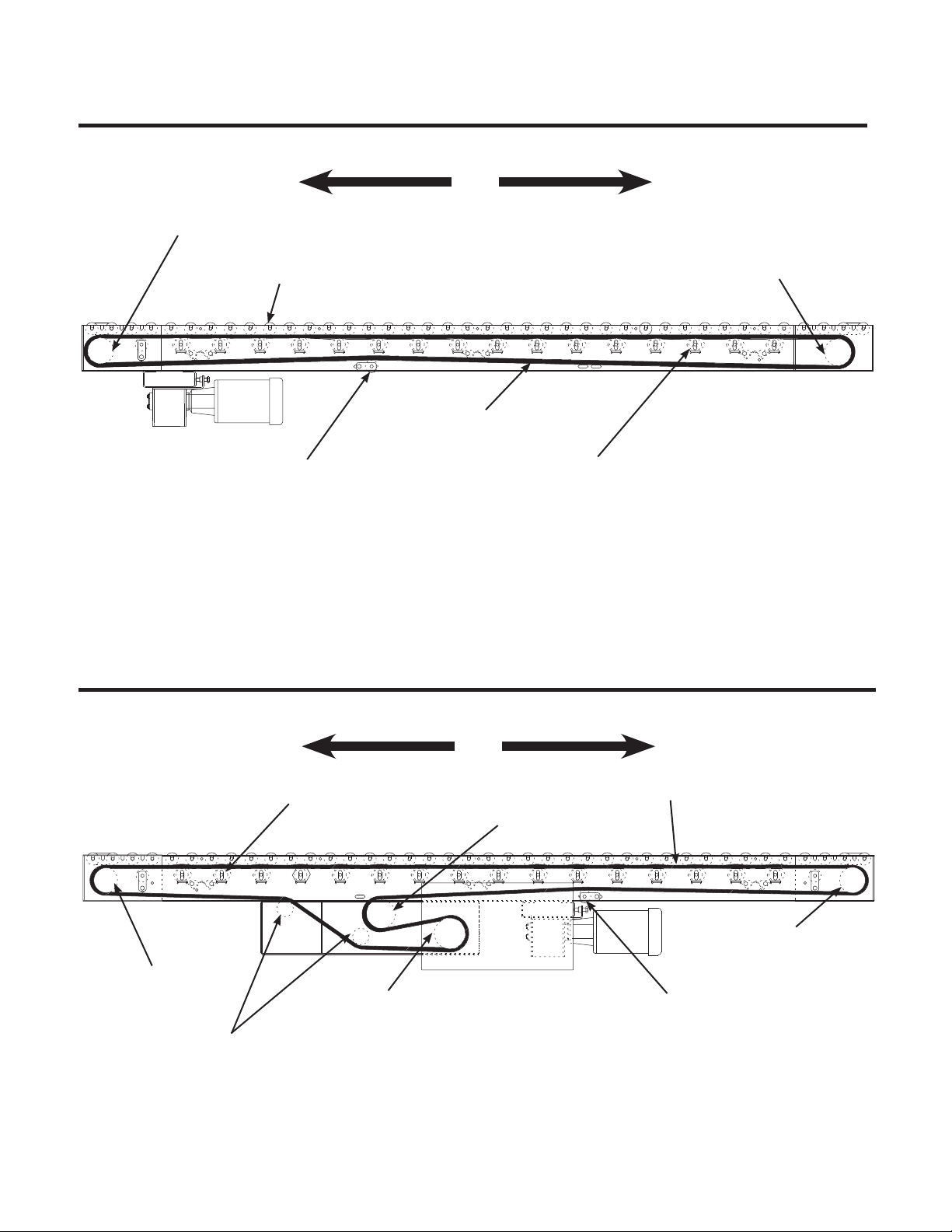
In most instances, live roller conveyor
frames are equipped with slots in the frame
for tread rollers. Why is this necessary?
When installed below 7’-0” elevation,
tread rollers must be designed to pop out
of the frame to prevent injury to operator
or individuals coming in contact with tread
rollers. However, when installed at 7’-0”
and greater elevation, tread rollers must
NOT be allowed to pop out. Individuals
stationed below the conveyor could be
injured by rollers that inadvertently become
free from conveyor frame. Therefore, a
belt driven live roller originally supplied
with slotted frame and pop out rollers, must
be modified if it is moved to 7’-0” or high-
er elevation. A special hold-down angle
must be installed to eliminate pop out roll-
ers. Also, when a live roller conveyor that
does not feature pop out rollers,
is used in an application below 7’-0”
elevation, conveyor MUST be modified to
include safety pop out rollers.
Contact Roach national sales at
870-483-7631 with conveyor serial
number for additional information.
WARNING: Belt driven live roller con-
veyors must have safety pop out tread
rollers when installed below 7’-0” eleva-
tion. Conversely, when installed at 7’-0”
or greater elevation, tread rollers must
NOT be allowed to pop out of frame.
Shut conveyor OFF and lock out power
source until above safety considerations
are completely adhered to.
*NOTE: Guard rail may be used to hold
rollers in frame when installed at 7’-0” or
higher elevations.
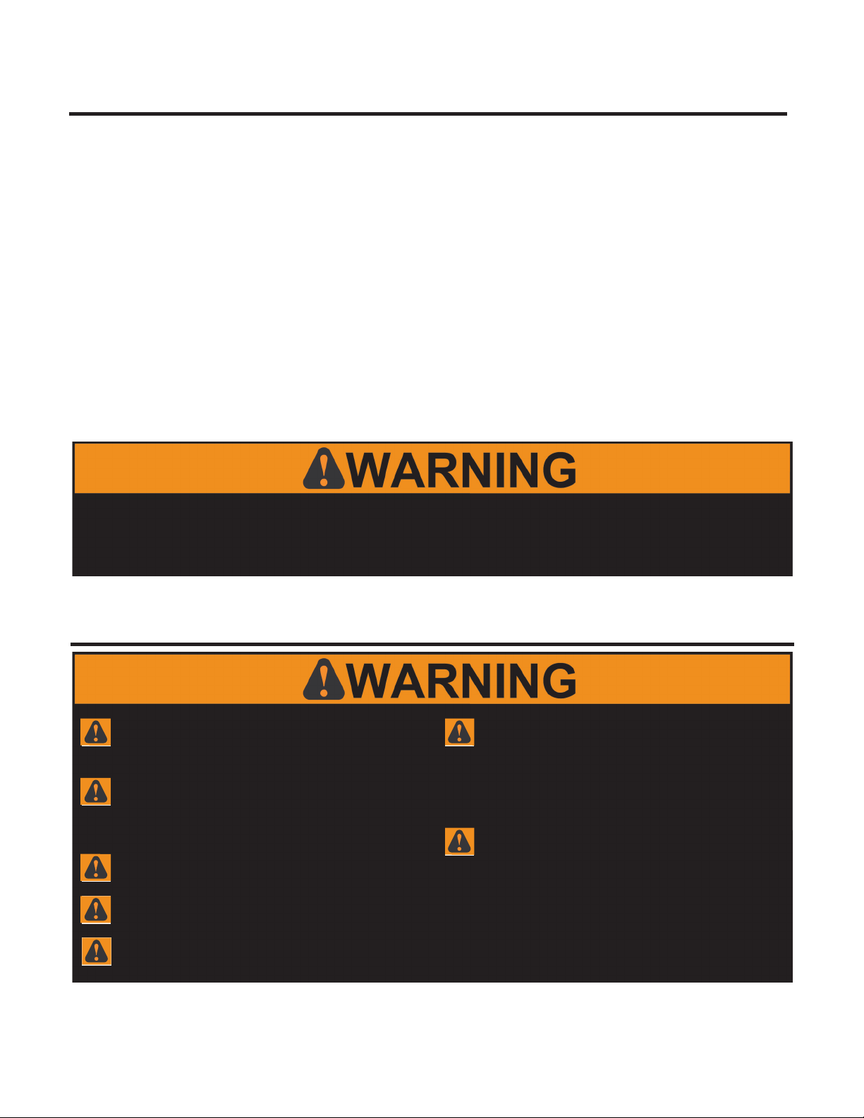
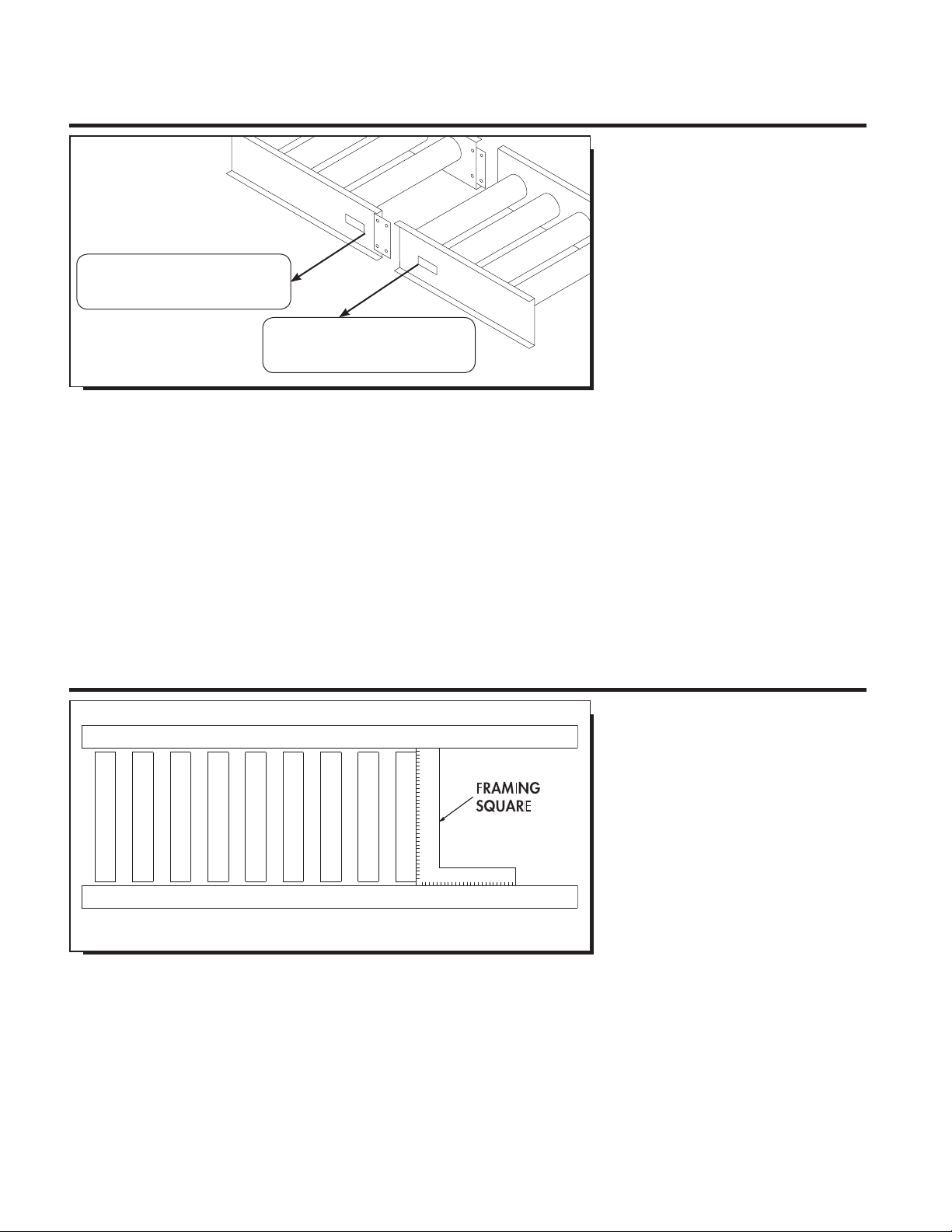
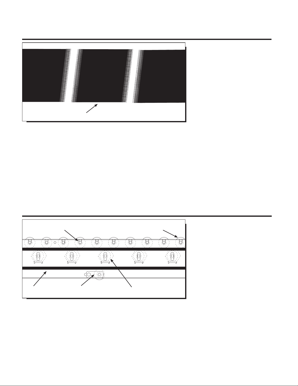
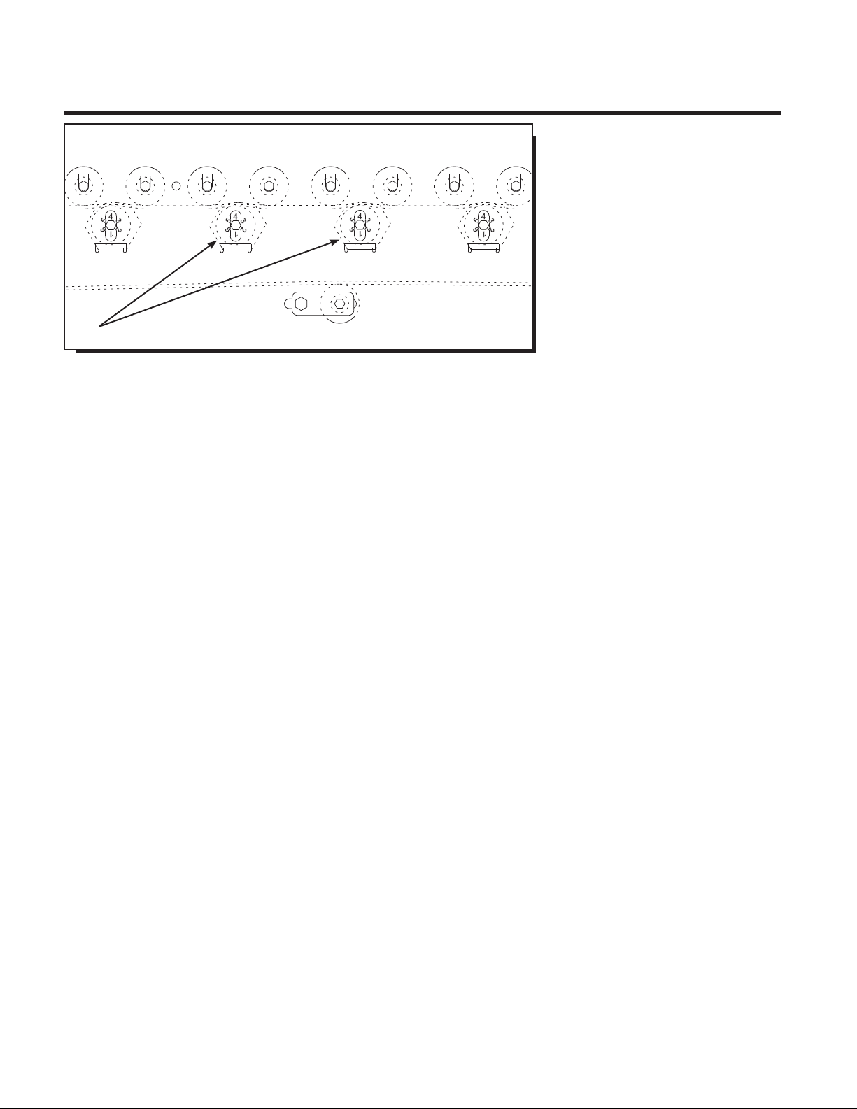
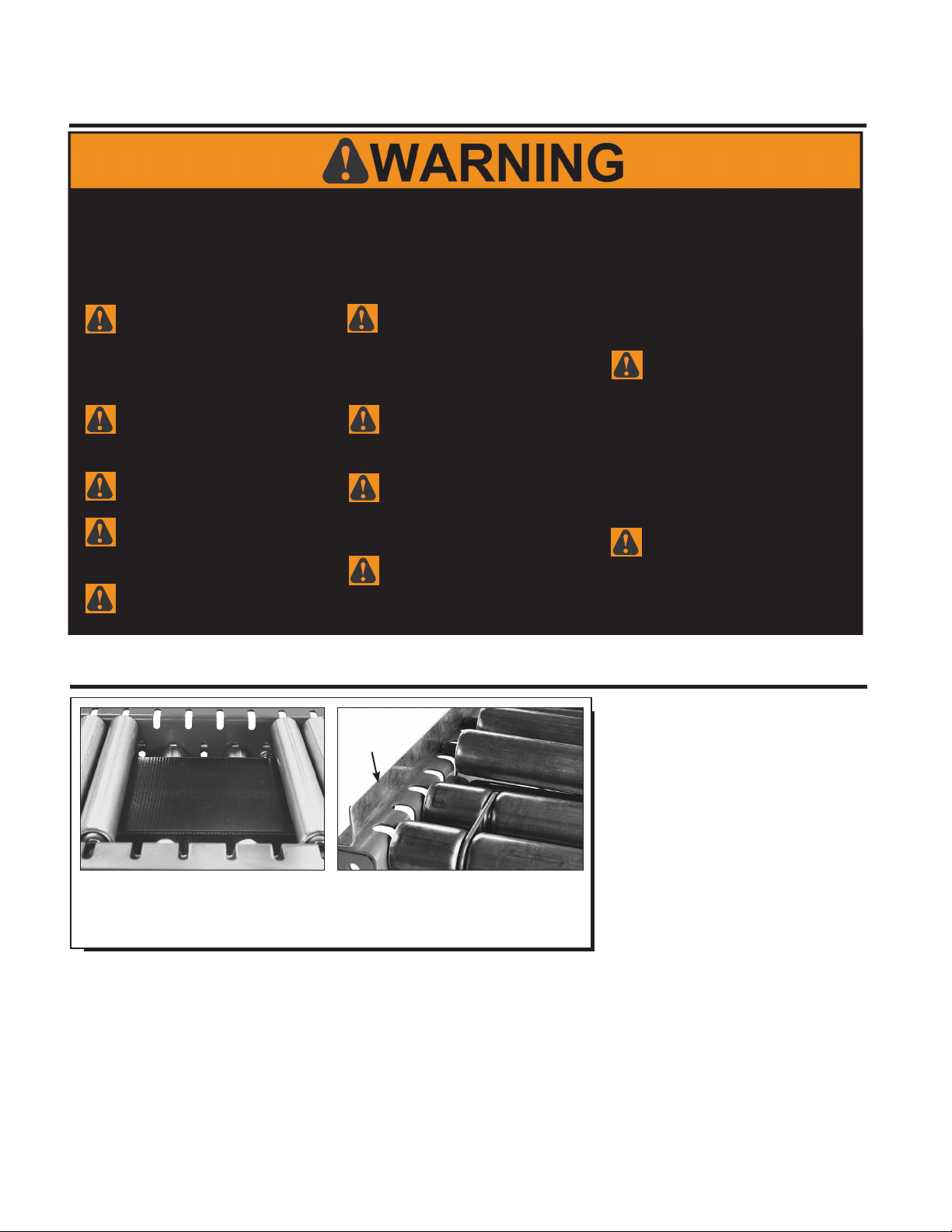
SLOTTED FRAME ALLOWS
ROLLERS TO EASILY POP OUT
(rollers removed for clarity)
WHEN GUARD RAIL IS ADDED,
DO NOT COVER POP OUT SLOTS
IN CONVEYOR FRAME*
GUARD
RAIL
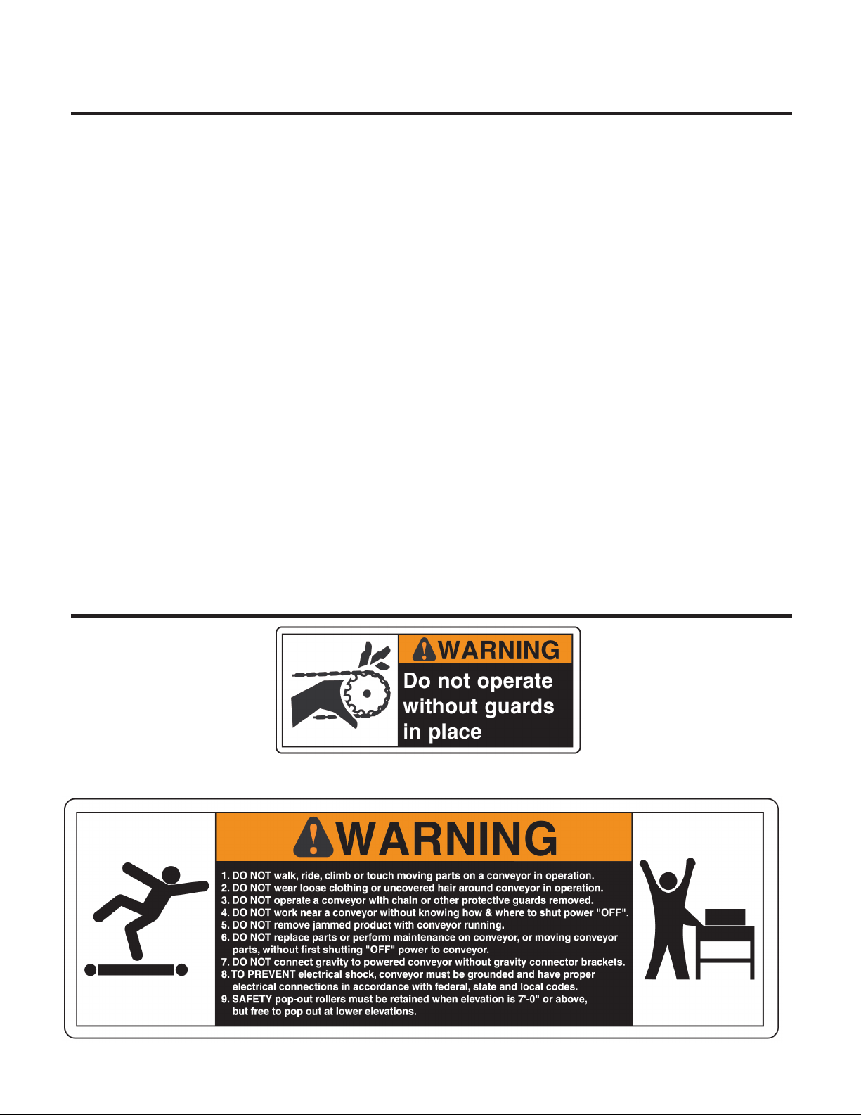
WARNING: All personnel coming in contact with this conveyor should be aware of the following safety guidelines
BEFORE USING OR WORKING AROUND CONVEYOR. NOTE: ALWAYS notify Roach Manufacturing
®
whenever any
conveyor is used in an application or condition other than was originally intended. Failure to notify Roach
®
may
allow conveyor to be operated in a hazardous operating condition. Injuries resulting from negligence or violation of
safety instructions hereby removes responsibility of product liability claims from Roach
®
.
Do not operate conveyor with
protective guards removed. This
includes chain guards, belt guards, snub
roller guards, center drive guards and
any other safety guard.
Do not walk, ride, climb, or touch
moving parts on a conveyor in
operation.
Do not wear loose clothing or
uncovered hair around conveyor.
Do not work near conveyor with-
out knowing how & where to shut
power “OFF” and lock out power source.
Do not remove jammed product
with conveyor running.
Do not replace parts or perform
maintenance on conveyor, or mov-
ing conveyor parts, without first shutting
“OFF” power to conveyor and locking out
power source.
Do not connect gravity to powered
conveyor without safety gravity
connector brackets.
To prevent electrical shock, conveyor
must be grounded, and have proper
electrical connections in accordance with
federal, state, and local codes.
Safety pop out rollers in conveyors
installed above 7’-0” elevation must
be retained by guard rail, clips, etc. Safety
pop out rollers must be allowed to pop out
when conveyors are installed at or below
7’-0” elevation.
It is the responsibility of conveyor
end-user to comply with all safety
standards including OSHA and other fed-
eral, state, and local codes or regulations.
Install protective guarding and other relat-
ed safety precautionary equipment to elimi-
nate hazardous operating conditions which
may exist when two or more vendors sup-
ply machinery for related use.
Any violation of above safety
instructions hereby removes all
product liability claims from Roach
Manufacturing Corporation
®
.