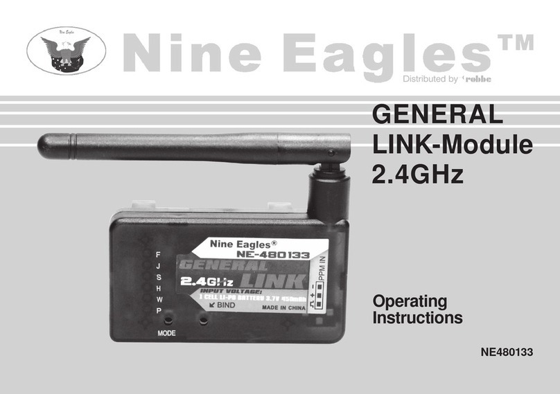
ROBBE RSC 890 mP User manual

Bedienungsanleitung / Operating instructions / Notice d'utilisation
Mikroprozessor - Fahrtregler RSC 890 µP / RSC 860 µPNo.
8352 /8151
DieRSC890/860sindmikroprozessorgesteuerteFahrtreglermitdenFunktionen"vorwärts"und"stop"
mit "bremsen". Durch ihre Konzeption eignen sie sich besonders für Kunstflug- und große Segelflug-
modelle. Speziel der RSC 890 wurde für die Belange der Wettbewerbspiloten der FAI Klasse F5B
entwickelt, in der Hochleistungsmotoren der PRO-Serie eingesetzt werden. Ein Mikroprozessor
überwacht sämtliche Funktionen des Reglers. Durch die werksseitige Voreinstellung können die
Geräte sofort in Betrieb genommen werden. Soll jedoch die Einstellung auf die persönlichen
Steuergewohnheiten angepaßt werden, so ermöglicht der Mikroprozessor das einfache Abspeichern
derSteuerknüppelpositionenfür"vorwärts"und"bremsen"mittelsTastendruck.Dervollelektronische
Aufbau arbeitet verschleißfrei. Diverse Schutzfunktionen sowie ein Selbsttest des Mikroprozessors
und eine Fehleranzeige sorgen für einen sicheren Betrieb des Reglers.
Technische Daten: RSC 890µP (RSC 860µP)
Funktionen: Stufenlos "vorwärts" -"stop" - "bremsen"
Akkuspannung : 8,4 - 36 V / 7-30 NC-Zellen
Fahrstrom: 90 A (60 A) / ca. 40 sek. (2 min.) Betriebszeit
Abmessungen: ca. 53 x 39 x 13 mm
Gewicht: ca. 68 g (58 g) -ohne Stecker
Kabelquerschnitt: 4 mm2 (2,5 mm2)
Besonderheiten:
µP- Einfache Handhabung, Funktionskontrolle und Fehlererkennung
durch Mikroprozessorsteuerung.
BRAKE -Bremse -> elektrische Motorbremse.
HEC -High Efficiency Clock -> hohe Motortaktfrequenz (feinfühlige
Drehzahlreglung).
POR -Power On Reset -> Schutz gegen unbeabsichtigtes Anlaufen des
Motors.
TOP -Thermal and Overload Protection -> Übertemperatur- und
Überlastungsschutz mit Kurzschlußerkennung
OPTO -Galvanische Trennung von Steuer- und Lastteil (Endstufe)
LED-Taster - Eingabetaste zur Programmierung, LED-Anzeige von Betriebs-
funktionen, Programmfunktionen und Fehlern
PourraccorderlevariateurRSC890/RSC860nousrecommandonslesystèmedeconnecteursGS4,
réf. 4056.
Werecommend the following connector systems for usewith the RSC 890 / RSC 860:GS4 (Order No.
4056).
Généralités et caractéristiques techniques:
Allgemeines und Technische Daten: Anschluß und Inbetriebnahme
Connection, using for the first time
Connexion et mise service
NachdemAnschlußunddemEinschaltenvonSenderundEmpfangsanlageführtder Mikroprozessor
einen Selbsttest durch, dessen erfolgreicher Abschluß durch dreimaliges kurzes Blinken der LED
angezeigt wird. Danach ist der Regler betriebsbereit. Im Teillastbereich blinkt die LED, bei Vollast ->
Dauerleuchten.
Achtung: Verpolung führt zur Zerstörung des Reglers
Caution: reversed polarity will wreck the controller
Attention: une inversion des polarités provoque la détérioration du variateur
Zum Anschluß der RSC 890 / RSC 860 empfehlen wir das Stecksystem GS4 Best.-Nr. 4056 .
GS4
Empfänger
Receiver
Récepteur
Motor
Motor
Moteur
Fahrakku
Drive battery
Accu de propulsion
GS4
rot / red / rouge = "+"
schwarz / black / noir = "-"
Fahrtregler/Motor-controller/Variateur
BRAKE-Bremse -> elektrische Motorbremse. Durch die Motorkurz-schlußbremswirkung wird ein
sauberes Anlegen von Klappluftschrauben bei E-Seglern erreicht.
HEC -High Efficiency Clock -> hohe Motortaktfrequenz (2 KHz),feinfühlige Drehzahlregelung,
stark stromsparend im Teillastbereich, längere Betriebszeiten, Reduzierung der thermi-
schen Belastung des Motors im Bereich Kollektor/Kohlebürsten.
POR -Power On Reset -> Schutz gegen unbeabsichtigtes Anlaufen beim Einschalten des
Senders, der Empfangsanlage oder Anstecken des Antriebsakkus, Regler wird nur durch
Wechseln der Steuerknüppelfunktion von "Aus" auf "Ein" eingeschaltet.
TOP -Thermal and Overload Protection ->beiÜberschreitenderzulässigen Reglertemperatur
durch Überlastung, schaltet der Mikroprozessor die Endstufe selbsttändig ab. Darüber
hinaus erkennt der Mikroprozessor einen Kurzschluß oder ein Blockieren des Antriebs-
motors und begrenzt in diesem Fall den Strom für Motor und Regler auf ungefährliche
Werte.
OPTO - Galvanische Trennung von Steu-
er-undLastteil(Endstufe),optimaleStör-unterdrückungbeihohenMotorleistungen,deshalb
beste Reichweite der Fernsteueranlage
Schutzfunktionen und ihre Bedeutung
Protective functions and how they work
Les fonctions de sécurité et leur signification
Une fois que la connexion a été établie et après mise en marche de l’émetteur et du récepteur, le
microprocesseur effectue un auto-test, dont le résultat positif est signalé par trois clignotements de la
LED.Ensuite le variateur est en ordre de marche: à mi-régime la LED clignote et luit en continu à plein
régime.
Connectthepowersystemandswitchonthetransmitterandreceiversystem. Themicro-processorwillrun
through a self-test procedure. The LED will flash three times quickly to indicate successful completion of
the test; the controller is now ready for use. In the part-load range the LED flashes; at full load it glows
continuously.
TheRSC890/860aremicro-processorbasedspeedcontrollersfeaturingthe functions „forwards“ and
„stop“withbrake.Becauseoftheirconception,theyarespecificallysuitableforaerobaticandbigglider
models.ParticularlytheRSC890 has been developed for the requirements of competition pilots in the
FAI-class F5B, in which high-performance motors of the PRO-series are used. A micro-processor
monitors all of the speed controller’s functions. The unit can be operated immediately with the factory
settingsitissuppliedwith.However,ifyouwishtofine-tunetheunittomeetyourpersonalpreferences,
the micro-processor provides a straightforward means of storing the stick positions for forwards and
brake, simply by pressing a button. The controller is fully electronic, and thus completely wear-free.
Various protective circuits, a micro-processor self-test and an error indicator system ensure that the
unit functions reliably.
Specification: RSC 890µP (RSC 860µP)
Functions: infinitelyvariablespeed control, „forwards“ - „stop“ - " brake"
Battery voltage: 8,4 - 36 V / 6 - 30 NC cells
Maximum current: 90 A (60 A) - approx. 40 sec.(2 minutes) running time
Dimensions: approx. 53 x 39 x 13 mm
Weight: approx. 68 g (58 g) -less plug
Cable cross-section: 4 sq mm (2.5 sq mm)
Special features:
µP- Integral micro-processor provides simple set-up, checking of
functions and fault detection
BRAKE -Electrical motor brake
HEC -HighEfficiencyClock->highpulsefrequencyforfinecontrolofmotor
speed
PCO -Power Cut Off -> under voltage protection
POR -Power On Reset -> guards against motor starting unintentionally
TOP -Thermal and Overload Protection -> guards against damage
through excessive temperature and overload; short-circuit detection
OPTO - Galvanic separation of control and power sections (output stage)
LED-button - Programming button, LED indicator for operational functions,
programming functions and errors
Introduction and specification:
LesRSC890/860sontdesvariateursdevitesseasservisparunmicroprocesseur;ilssontpourvusdes
fonctions suivantes: marche avant, arrêt et freinage électrique. Dû à leur conception, ils sont
spécialementadaptésaux modèlesdevoltige etauxgrandsplaneurs.LeRSC890 aétéspécialement
conçu pour les intérêts des pilotes de compétition de la classe FAI F5B, dans laquelle des moteurs
puissant de la série PRO sont utilisés. Un microprocesseur surveille un grand nombre des fonctions
du régulateur. L’appareil est réglé dans nos ateliers et peut donc être mis en oeuvre directement. Si
vous souhaitez toutefois l’adapter à vos habitudes de pilotage, le microprocesseur permet de saisir la
position des manches pour la marche avant et le frein électrique par simple pression sur un bouton.
La structure électronique ne connaît pas d’usure. Divers éléments de protection, tels la fonction auto-
test du microprocesseur et l’affichage des dérangements permettent au variateur de fonctionner en
toute sécurité.
Caractéristiques techniques:RSC 890 µP (860 µP)
Fonctions: progressive: marche avant, arrêt, frein électrique
Tension de l’accu: 8,4 à 36 volts (7 à 30 éléments Cd-Ni)
Courant: 35 ampères / approx.6 minutes
Encombrement: approx. 59 x 35 x 13 mm
Poids: approx. 51 g (sans connecteur)
Section des fils: 2,5 mm2
Spécificités
µP- mise en marche simple, contrôle de fonctionnement et détection de
dérangements par l’intermédiaire d’un microprocesseur
BRAKE -Frein électrique
HEC -High Efficiency Clock -> haute fréquence d’impulsion du moteur
(régulation très précise du régime)
POR -Power On Reset -> protection contre le démarrage intempestif du
moteur
TOP Thermal and Overload Protection -> protection contre les excès de
température et de charge avec détection des courts-circuits
OPTO - séparation galvanique de la commande et du bloc d’alimentation
(étage final).
Touche à LED - Touche de programmation, affichage à LED des modes, fonctions de
programme et de dérangement
Rückseitenansicht / Rear view / Vue arrière
Motoranschlüsse
Motor connections
Raccords moteur
Empfängeranschluß
Receiver connection
Raccord récepteur
Akkuanschlüsse
Battery connections
Raccords accu
LED-TASTER
LED button
Touche à LED
Bedienelemente / Controls / Eléments de commande
Motoranschluß "+" (rot)
motor connection "+" (red)
Raccord moteur „+“, (rouge)
Motoranschluß "-" (schwarz)
motor connection "-" (black)
Raccord moteur „-“, (noir)
Empfängeranschluß
Receiver connection
Raccord du récepteur
Akkuanschluß "-" (schwarz)
battery connection "-" (black)
Raccord accu „-“, noir
Akkuanschluß "+" (rot)
battery connection "+" (red)
Raccord accu „+“, rouge
Bei falscher Drehrichtung
Motorstecker
umpolen.
If the motor rotates in the
wrong direction, swap over
the motor plugs
Lorsque le moteur tourne
dans le mauvais sens,
inverser

Bedienungsanleitung / Operating instructions / Notice d'utilisation
Mikroprozessor - Fahrtregler RSC 890 µP / RSC 860 µPNo.
8352 /8151
- Beachten Sie die technischen Daten der Regler.
- Polung aller Anschlußkabel beachten.
- Kurzschlüsse der Kabel vermeiden.
- Antriebsmotor wirkungsvoll entstören.
- Die Regler so einbauen bzw. verpacken, daß sie nicht mit Fett, Öl oder Wasser in Berührung kommen
können.
- Note the speed controller’s operating limits and stay within them.
- Check the polarity of all cables.
- Avoid short-circuits.
- Fit effective interference suppressors to the drive motor.
- Install the controllers and protect them in such a way that they cannot come into contact with grease, oil
or water.
- Observer scrupuleusement les caractéristiques techniques du variateur,
- Observer absolument les polarités,
- Eviter de mettre les fils en court-circuit,
- Antiparasiter efficacement le moteur,
- Installer les variateurs et les emballer de telle manière qu’ils n’entrent pas en contact avec de l’huile, de
la graisse ou de l’eau.
Die LED blinkt 6x -> Einstellung beendet
Erfolgt dieses Zeichen nicht, so konnten die eingegebenen Schaltpunkte nicht übernommen werden.
Programmieren Sie die Schaltpunkte neu und beachten Sie, daß die Steuerknüppelpositionen mindestens
15°(3-4 Rastpunkte) voneinander entfernt sind.
LED flashes 6 x -> adjustment process complete
Ifthis signaldoes notappear,thenthecontrollerwasunable toaccept thevalues youhave entered. Program
the switching points again, and check the following points: the stick positions must be separated by at least
15 degrees (3 - 4 ratchet clicks).
Lorsque la LED clignote 6x -> le réglage est terminé
Si ce sextuple clignotement n’intervient pas, cela signifie que les points de commutation n’ont pas été saisis.
Reprendre la programmation des points de commutation en se souvenant que ces positions des manches
doivent au moins présenter un écart de 15°(3 à 4 crans) l’une par rapport à l’autre.
Fehlererkennung durch den RSC
RSC error detection
Détection de dérangements par le variateur RSC
Schutzfunktionen und ihre Bedeutung
Protective functions and how they work
Les fonctions de sécurité et leur signification
BRAKE-Electrical motor brake. Braking effect with motor short circuited ensures that the folding
propeller of an electric glider folds back reliably.
HEC -HighEfficiencyClock->highpulsefrequency(2kHz)forfinecontrolofmotorspeed. Substantial
current saving in the part-load range, longer running times. Reduces thermal load on the motor
in the commutator / carbon brush area.
POR -PowerOnReset->guardsagainstthemotorstartingwhenthetransmitterorreceiverisswitched
on, or when the drive battery is plugged in. Controller can only be switched on by moving the
throttle stick from "off" to "on".
TOP -Thermal and Overload Protection -> if the speed controller is overloaded, and its maximum
permissible temperature is exceeded, the micro-processor automatically switches off the output
stage. Themicro-processoralso detects short-circuitsanda stalled drivemotor,and in thiscase
limits the current for motor and controller to a non-critical value.
OPTO - Galvanic separation of control and power sections (output stage). Optimum interference
suppression with high-power motors, maintains maximum radio control system range.
BRAKE-Frein -> Frein électrique. Efficacité du freinage par court circuitage du moteur assure le
repliage parfait des pales des hélices des planeurs électriques.
HEC -High Efficiency Clock -> haute fréquence d’impulsion (2 kHz) du moteur qui procure une
régulation très précise du régime et s’avère très économique d’un point de vue énergétique au
niveau des gammes de régime à charge partielle et donne donc une meilleure autonomie et une
réduction de la charge thermique du moteur dans la zone collecteur/balais de charbon
POR -Power On Reset -> protection contre le démarrage intempestif du moteur lorsque l’émetteur ou
le récepteur est mis en marche ou lorsque l’accu du moteur est connecté. Le variateur assure
l’asservissementdumoteur uniquementlorsquele manchedecommande est déplacédu neutre
„Hors fonction“ vers „Marche“.
TOP -Thermal and Overload Protection ->lorsque la température excèdelavaleuradmissible par le
variateur, le microprocesseur commute automatiquement l’étage final. Par ailleurs, le
microprocesseur détecte la présence de courts-circuits ou le blocage du moteur et ramène dans
ce cas le courant du moteur et du variateur à des valeurs ne présentant pas de danger.
OPTO - séparation galvanique de la commande et du bloc d’alimentation (étage final) qui constitue une
protection efficace contre les dérangements lorsque le moteur tourne à pleine puissance, le
principe assure également une meilleure portée de l’ensemble de radiocommande.
1. Sender einschalten / Switch on the transmitter / Mettre l’émetteur en marche.
2. Empfangsanlage einschalten / Switch on the receiving system / Mettre l’ensemble de réception en
marche.
3. Taster (mittels Kugelschreiber) betätigen, bis LED erlischt. Der Regler ist nun aufnahmebe-
reit für die neuen Steuerknüppelpositionen, die er durch unterschiedliche Blinksignale
abfragt. Erlischt die LED nur kurz, liegt kein Steuersignal an. Fernsteueranlage bzw.
Empfangsanlage überprüfen.
Pressthebutton(usinga ball-pointpen),andtheLED willgoout. Thecontrolleris nowready
to accept the new stick positions, which it requests by means of different flashing signals. If
the LED only goes out briefly, it is not receiving a valid control signal. Check that the radio
control system is connected, switched on and working properly.
Activer la touche (à l’aide de la pointe d’un stylo à bille) jusqu’à ce que la LED s’éteigne. Le
variateurest dèslors prêtàenregistrerlesnouvellespositionsdes manchesqu’il signalepar
diversclignotements dela LED.Si laLEDs'éteigneseulementbrièvement,ellenereçoitpas
de signal de commande. Tester le réglage à l’aide de l’ensemble de radiocommande.
Vorwärtsposition / Forward position / Position marche avant
4. LED blinkt 2x Pause ...
LED flashes 2 x, pauses, ...
La LED clignote 2x fait une pause puis reclignote ...
Steuerknüppel auf die gewünschte Vorwärtsposition bringen.
Move stick to desired forwards position.
Amener le manche sur la position souhaitée pour la marche avant.
Position mit Taster bestätigen
Confirm position by pressing button
Confirmer la position avec le bouton
. . .
Bremsposition / Brakel position / Position de freinage
5. LED blinkt 3x Pause ...
LED flashes 3 x, pauses, ...
La LED clignote 3x fait une pause puis reclignote ...
. . .
Steuerknüppel auf die gewünschte Bremsposition bringen.
Move stick to desired brake position.
Amener le manche sur la position souhaitée pour lefreinage.
Position mit Taster bestätigen.
Confirm position by pressing button.
Confirmer la position avec le bouton.
Die Neutralposition (Stop ohne Bremsfunktion) befindet sich ca. 15 Grad (3-4 Rastpunkte) vor der
Bremsposition.
The neutral position ("Stop" without brake function) is approx. 15 degrees (3 - 4 ratchet clicks) in front of
the brake position.
La position neutre ("arrêt" sans fonction de freinage) se trouve environ 15 degrés (3 - 4 crans) devant le
position de freinage.
Bei Verwendung von Starrluftschrauben ist die Bremsfunktion nicht erforderlich und nicht erwünscht.
Daher zur Unterdrückung der Bremsfunktion wie folgt programmieren:
- Vollgas wie beschrieben programmieren (Trimmung in Mittelstellung).
- Die Trimmung 1 - 2 Markierungsstriche in Richtung „Stop“ verstellen. Den Steuerknüppel in Endstellung
„Stop“ bringen.
- In dieser Position „Motorstop“ programmieren.
- Trimmung wieder in Mittelstellung bringen. Die Bremsfunktion ist damit ausgeschaltet.
- Eine Überprüfung der Knüppelstellungen durchführen. In der Stellung „Stop“ darf der Motor nicht anlaufen,
die Bremse darf nicht wirken. Bei Abweichungen die Trimmposition korrigieren.
If you are using non-folding propellers the brake function is neither necessary nor desirable.
To disable the brake function the unit should be programmed as follows:
- Program the full throttle setting as already described (trim at centre).
- Move the trim slider 1 or 2 clicks in the direction of „stop“. Now move the stick to the „stop“ end-point.
- Program the unit to „motor stopped“ in this position.
- Move the trim slider back to centre. The brake function is now switched off.
- Check the stick settings: at the „stop“ position the motor should not run, and the brake should not operate.
If this is not the case, adjust the trim slider to correct.
Avec les hélices fixes (non repliables) la fonction de freinage n’est pas nécessaire ni souhaitable.
En conséquence, discriminer la fonction de freinage en programmant comme suit:
- Programmer le régime plein gaz comme décrit (trim en position médiane).
- Décalerlestraitsdeprogrammation1-2demanche(trim)endirection„Arrêt“.Amenerlemancheenposition
„Arrêt“.
- Dans cette position du manche, programmer „Arrêt moteur“.
- Amener à nouveau le manche en position médiane. La fonction freinage est ainsi coupée.
- Effectuer un cotrôle des positions du manche. En position „Arrêt“, le moteur ne doit pas démarrer et le frein
doit être inefficace. Si ce n’est pas le cas, corriger la position du manche (trim).
Soll der Regler entsprechend den eigenen Steuergewohnheiten eingestellt werden, so ist wie folgt zu
verfahren:
If you wish to adjust the controller to suit your particular requirements, this is the procedure:
Si vous souhaitez adapter le réglage du variateur à vos habitudes de pilotage, procédez comme suit:
Einstellung der Steuerknüppelpositionen
Adjusting the stick positions
Réglage de la position des manches
Die Knüppelstellungen werden so abgespeichert, daß immer eine Vollaussteuerung der Vorwärtsfunktion
erreicht wird. Die Programmierung ist in "Neutralposition" der Steuerknüppeltrimmung durchzuführen. Eine
Veränderung der Einstellung ist nur möglich, solange der Regler noch nicht betrieben wurde. Soll die
Einstellung nach dem Betrieb geändert werden, so ist die Empfängerakkuspannung kurz zu unterbrechen.
Diese Schutzfunktion verhindert eine Veränderung der Einstellung während des Betriebs. Der Regler kann
sowohl im Normal- als auch im Servo-Reverse-Betrieb programmiert werden.
When the stick positions are stored, the full control range of the forwards functions is maintained. Programe
in"trimneutralposition".Thestickpositionvaluescan onlybeadjusted beforethecontrollerisrun. Ifyouwish
to change the settings after running the model, disconnect the reciver battery beforehand. This is a safety
measure, and ensures that the adjustment does not change during operation. The controller can be used in
the normal direction and in reverse, i.e. when the transmitter’s servo reverse function is used.
Le réglage initial du manche des gaz est tel qu’on dispose d’un asservissement complet de la marche avant
et de la marche arrière. Programmer dans la position neutre du trim. Une modification de ce réglage n’est
possiblequelorsquelevariateurn’apasencoreétémisenoeuvre.Sileréglagedoitinterveniraprèsunemise
en service, il faut couper l’alimentation afin d’éviter toute modification d’ajustement pendant le service. Le
variateur peut être réglé aussi bien en mode „normal“ qu’en mode „inversé“.
La LED permet de signaler divers types de dérangements. Types de dérangements:
- la LED clignote 3x longuement - dérangement détecté lors de l’auto-test -> débrancher brèvement le
variateur ou, si nécessaire, reprogrammer les points de commutation.
-Dérangements du signal du récepteur
- Lorsque la durée du dérangement n’excède pas approx. 0,2 seconde -> le dernier signal reconnu
comme correct est retenu.
- Lorsque la durée du dérangement excède 0,2 seconde sans dépasser 2 secondes -> l’étage final
commute jusqu’à ce qu’un nouveau signal correct intervienne.
- Lorsqueladuréedudérangementexcède2secondes->l’étagefinalestcoupé.Ilestrétabliuniquement
par un déplacement du manche de la position „neutre“ à une position „EN“, marche avant ou marche
arrière.
- Les variateurs RSC réduisent le courant jusqu’à une valeur admissible si nécessaire.
- S’il y a un courts-circuit ou un blocage du moteur, les variateurs réduisent le courant du moteur et du
variateur jusqu’à des valeurs qui ne présentant pas de danger.
- Si la température excède la valeur admissible, les variateurs commutent l’étage final. Les variateurs
peuvent être utilisé après refroidissement.
Sivousn’êtespasenmesured’éliminerundérangement,faitesparvenirvotrevariateurànotreserviceaprès-
vente ou à votre détaillant spécialiste. Betriebshinweise
The speed controller in use
Conseils de mise en oeuvre
Über die LED werden unterschiedliche Fehler angezeigt.
- LED blinkt 3x lang - Fehler beim Selbsttest -> Regler kurz von der Spannungsversorgung trennen, bzw.
Schaltpunkte neu programmieren.
-Störungen des Empfängersignals
- Störungsdauer unter ca. 0,2 Sekunden -> Das letzte gültige Signal wird verwendet.
- Störungsdauer von 0,2 bis 2 Sekunden -> Endstufe schaltet ab bis ein neues gültiges
Signal anliegt,
- Störungsdauer über 2 Sekunden -> Endstufe schaltet ab.
Durch Betätigen des Steuerknüppels von Position "Aus" auf "Ein " wird die Endstufe wieder
eingeschaltet.
- Bei zu hohen Motorströmen reduzieren die RSC den Strom auf einen zulässigen Wert.
- Bei Kurzschluß oder Blockieren des Antriebsmotors begrenzen die RSC den Strom auf einen für den
Motor und Regler unkritischen Wert.
- Bei Übertemperatur schalten die Regler ihre Endstufen ab. Nach Abkühlung können die
Regler erneut eingeschaltet werden.
Lassen sich Fehler nicht beseitigen, ist der Regler an unseren Service einzusenden, bzw. zur Einsendung
bei Ihrem Fachhändler abzugeben.
The LED indicates various errors as follows:
- LED flashes 3 x (long flashes) - error during self-test -> briefly disconnect controller. R e -
program switching points if necessary.
-Receiver signal interference
- Duration of interference less than about 0.2 seconds -> the last valid signal is retained.
- Duration of interference longer than 0.2 seconds, shorter than 2 seconds - > output stage switches
off until a new valid signal is received.
- Duration of interference longer than 2 seconds -> output stage switches off. Move the stick from the
„neutral“ position to „On“ (forwards / reverse) to switch the output stage on again.
- The RSC reduce the current to a permissible value if necessary.
- In case of short circuit or a stalled drive motor, the RSC limit the current for motor and controller to a
non-critical value.
- If the maximum permissible termperature is exceeded, the controller switches off the output stage.
The controllers can be switched on again after cooling down.
Ifyouareunabletocureoperationalerrors,pleasesendthecontrollerbacktoourServiceDepartmentorhand
it to your dealer for return to us.
robbe Form 40-3577 BAJF
This manual suits for next models
3
Other ROBBE Control Unit manuals
Popular Control Unit manuals by other brands
Stafsjö
Stafsjö XV Maintenance instructions
Weller
Weller WD 2M operating instructions

Vapac
Vapac VapaNet LFE Series Installation & operation manual
Phylrich
Phylrich DFPHYID 001 Series Installation & owner's manual

Georg Fischer Piping Systems
Georg Fischer Piping Systems 514 operating instructions
Festo
Festo CPX-CMIX-M1-1 manual
