4
A. GENERAL:
Be sure that all pipes and fittings used are clean, free of chips,
dirt and moisture. If pipe compound or shellac is used, apply a
small amount above the second or third male thread only.
DO NOT GET PIPE COMPOUND OR SHELLAC INSIDE
RELAY.
B. MOUNTING:
When installing the relay, do not remove the plastic plugs from
the connections until ready to install fittings. Do not remove
any metal pipe plugs.
The relay may be mounted in any position. Due to its size and
OPERATION:
The illustration (Figure 2) shows a relay for averaging 7 input
pressure signals. The operation of the smaller units is similar.
With zero input pressure at all input ports and the biasing
spring adjusted so that it is not exerting any force in either
direction, the unit is in a balanced position. In this balanced
position, both the supply and exhaust seats of the valve are
closed and there is no air flow. The diaphragm areas are
related in such a manner that the effected force of any input
pressure is downward. Therefore, with the unit in a balanced
position, introduction of any input pressure will create a
downward force which will move the center assembly down,
opening the supply seat of the valve and permitting supply air
pressure to flow into the output chamber. This output pressure
is channeled into all of the balancing chambers. The
diaphragms of the balancing chambers are related so that this
output air pressure creates an upward force. As the output
pressure approaches the average input pressure, the center
weight, it may be supported by the air lines. If more secure
mounting is desired, use the mounting bracket furnished as
shown in Figure 1. Use two 1/4" bolts, toggle bolts or wood
screws as required by the installation. Bracket may be
removed or inverted by removing two lock nuts.
C. CONNECTIONS:
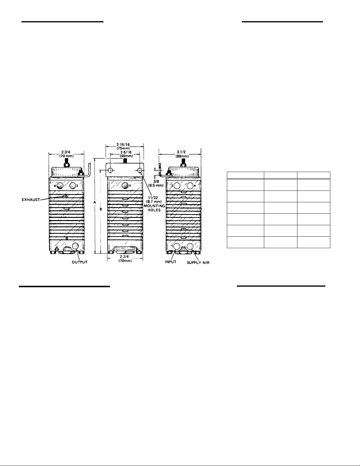
The input, supply and output ports are 1/4" female NPT.
Make the air connections to the proper ports as shown in
Figure 1. The air supply must be clean, dry and regulated
(use filter-regulator #97478) and must not exceed 60 psig (4.2
bar).
assembly will be returned to the balanced position, permitting
the supply seat of the valve to close, throttling the flow of
supply air.
Should any or all of the input pressure decrease, the upward
force of the output pressure would be greater than the
downward force of the input pressures. Then the center
assembly would move upward, opening the exhaust seat and
thereby exhausting the output air until the decreased output
pressure again balances the input pressures.
The spring assembly permits biasing the output pressure to a
maximum of ±18 psig (1.2 bar) divided by the number of
inputs. In the 6 input signal relay, this means that the output
pressure may be biased ±3 psig (0.21 bar). In the 2 input
signal relay, it may be biased ±9 psig (0.62 bar). This is
accomplished by turning the adjusting screw in the top of the
assembly to either extend or compress the spring.
SECTION II - INSTALLATION
SECTION III - OPERATION
Figure 1
NUMBERED PORTS ARE INPUT SIGNAL
CONNECTIONS
DIMENSIONS
MODEL NO. A B
CR103-A2 4-7/8″
(124 mm) 4″
(102 mm)
CR103-A3 5-3/8″
(137 mm) 4-1/2″
(114 mm)
CR103-A4 5-7/8″
(149 mm) 5″
(127 mm)
CR103-A5 6-3/8″
(162 mm) 5-1/2
(140 mm)
CR103-A6 6-7/8″
(175 mm) 6″
(152 mm)
CR103-A7 7-3/8″
(187 mm) 6-1/2″
(165 mm)
SIGNAL PORT 5 IS ON THE FACE OPPOSITE
PORT 7
DIMENSIONS