Robinson Poly-Pitch User manual

8ft Wide “Poly-Pitch” Assembly Instructions

8ft Wide “Poly-Pitch” Assembly Instructions
Copyright © Robinson Polytunnels 2014 2
CONTENTS
Section Page
1. FOUNDATION TUBES: Option A –Concreted Foundation Tubes 3
2. FOUNDATION TUBES: Option B –Ground Anchor Plates 5
3. TIMBER BASE RAILS (Along the sides) 6
4. STEEL FRAME ASSEMBLY & INSTALLATION 7
5. TIMBER END FRAME ASSEMBLY & INSTALLATION 10
6. TIMBER BASE RAIL (Across the ends) 11
7. TIMBER SIDE RAIL (OPTION) 12
8. ROLL UP CURTAIN (OPTION) 13
9. END PANELS & SIDE NETTING (INCLUDED WITH TIMBER SIDE RAIL OPTION) 15
10. FITTING THE ANTI HOT SPOT TAPE 16
11. FITTING THE POLYTHENE –POLYTHENE TO BASE RAIL 17
12. FITTING THE POLYTHENE –POLYTHENE TO SIDE RAIL 19
13. DOOR ASSEMBLY & INSTALLATION 21
PARTS LIST 23
POLYTUNNEL MAINTENANCE 26
8ft Wide “Poly-Pitch” Assembly Instructions
Copyright © Robinson Polytunnels 2014 3
Work Safely
When you tackle a job it is important to work safely. Please consider the following points when building your
Polytunnel.
Keep your work area tidy. A tidy site is a safe site.
Use the correct tools for the job.
Wear gloves where practical. Components may have sharp edges. Timber may have splinters.
Take care when using tools such as hammer, spade, drill, knife, scissors.
Consider other people, particularly children.
Tools Required
You will require a few tools to assemble your Polytunnel which are usually available in most households.
Hammer
Wood saw
Spirit level
Cordless drill
9mm drill bit
String line
Staple gun (optional) or stapler
13mm spanners or sockets
Tape measure
Scissors or craft knife
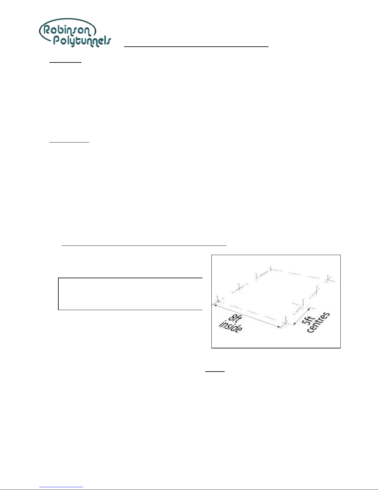
1. FOUNDATION TUBES: Option A –Concreted Foundation Tubes
1Set two string lines to the width of the polytunnel
(8ft apart). Ensure they are parallel.
Tip! It’s best to put your polytunnel on a flat, level site.
A fall lengthways is easy to accommodate. A fall
sideways should be limited to about 6” over the
width of the polytunnel.
2Set another string line for the end of the polytunnel.
Ensure the “end” string line is perpendicular to the
“length” string lines.
3Mark the ground at each foundation position, to the outside of the “length” string lines at 5ft centres
until the full length is reached.
4Temporarily remove the string lines so they don’t get in the way whilst digging.
5Dig a hole for each Foundation Tube, approximately 25cm square x 35cm deep.
6Reinstate the string lines.
7Fill the excavated holes with freshly-mixed concrete (or use post-mix, following the instructions on the
bag).

8ft Wide “Poly-Pitch” Assembly Instructions
Copyright © Robinson Polytunnels 2014 4
8Slot the Foundation Tubes into the concrete, to the outside of the string lines. Make sure the Foundation
Tubes are vertical, touching the string line and spaced at 5ft centres. The Foundation Tubes should be
protruding above ground by approximately 35cm.
Tip! Allow the concrete to set before you try to install
the framework!
8ft Wide “Poly-Pitch” Assembly Instructions
Copyright © Robinson Polytunnels 2014 5
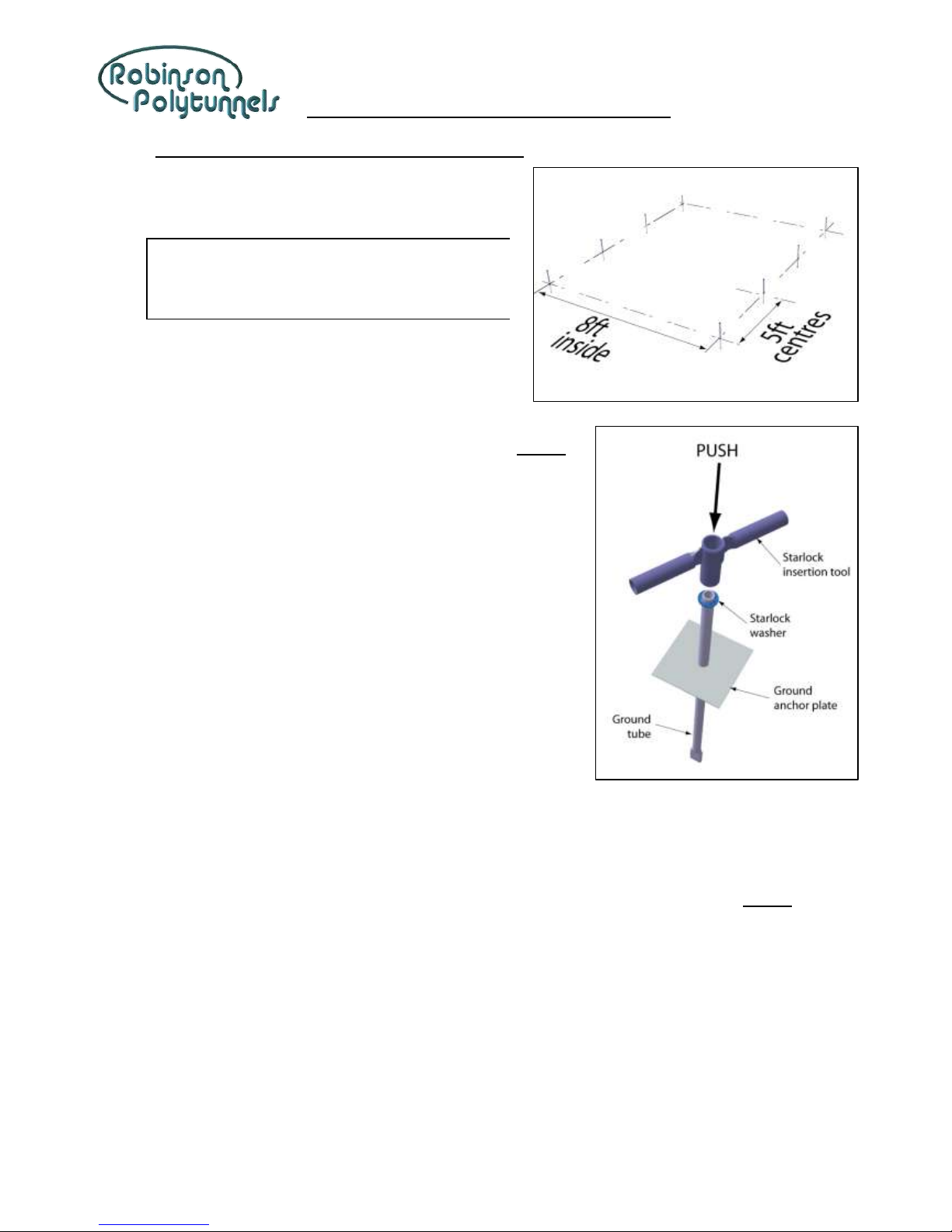
2. FOUNDATION TUBES: Option B –Ground Anchor Plates
1Set two string lines to the width of the polytunnel
(8ft apart). Ensure they are parallel.
Tip! It’s best to put your polytunnel on a flat, level site.
A fall lengthways is easy to accommodate. A fall
sideways should be limited to about 10cm over the
width of the polytunnel.
2Set another string line for the end of the polytunnel.
Ensure the “end” string line is perpendicular to the
“length” string lines.
3Mark the ground at each foundation position, to the outside
of the “length” string lines at 5ft centres until the full length is
reached.
4Temporarily remove the string lines so they don’t get in the
way whilst digging.
5Dig a hole for each Foundation Tube, approximately 25cm
square x 35cm deep.
6Slot the ground anchor plates over the Foundation Tubes.
And lock in place with the starlock washers. Starlock washers
are inserted using the insertion tool.
a. Hold the insertion tool over the starlock washer on
top of the Foundation Tube.
b. Gently tap the insertion tool with a hammer until the
washer is located on the Foundation Tube by about
5cm.
c. Using the insertion tool, push the starlock washer right down to the ground anchor plate until it
is secured.
7Reinstate the string lines.
8Insert the Foundation Tube and anchor plate assembly into the excavated holes, to the outside of the
string line. Make sure the Foundation Tubes are vertical, touching the string line and spaced at 5ft
centres. The Foundation Tubes should be protruding above ground by approximately 35cm.
9Backfill the excavated holes, checking that the Foundation Tubes are still in the correct position. Stamp
on the soil to ensure the soil is well-compacted.

8ft Wide “Poly-Pitch” Assembly Instructions
Copyright © Robinson Polytunnels 2014 6
3. TIMBER BASE RAILS (Along the sides)
1Lay the lengths of 38mm x 89mm timber along the side of the polytunnel, end-to-end. Join together with
the timber joint plates and 30mm twist nails.
2Position the joined timbers against the foundation tubes and flush with the M20 fitting at one end.
3Drill a hole in the timber, through the hole in the M20 fitting. Bolt with an M8 x 50 coach bolt and nut.
4Do the same, fixing to the M20 fitting at the other end of the polytunnel.
5Fix the timber base rail to the inner foundation tubes with the SC20 fittings and M8 x 65 coach bolts.
6Spy through from one end to make sure the base rail is straight and adjust if necessary.
7Trim off the surplus timber flush with the outside face of the M20 fitting.
8Fix the timber base rail to the foundation tubes on the other side of the polytunnel. Spy through from
the side of the polytunnel to make sure both base rails are parallel and adjust if necessary.
8ft Wide “Poly-Pitch” Assembly Instructions
Copyright © Robinson Polytunnels 2014 7
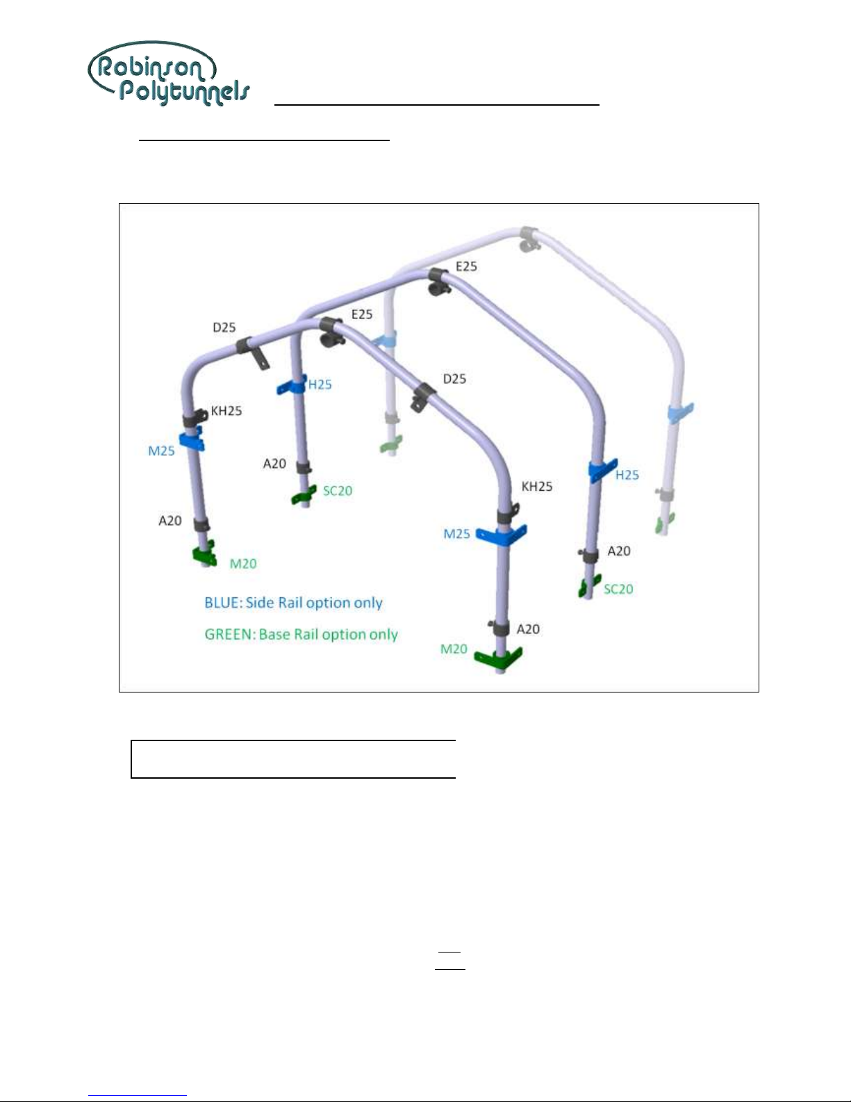
4. STEEL FRAME ASSEMBLY & INSTALLATION
1Assemble the hoops. Lay the components out on a flat surface with the fittings in the positions shown.
Please note the orientation of the fittings.
Tip! If you have ordered crop/tie bars, it’s easier to put
the KH25 fittings onto the inner hoops now.
2Each arch is in 3 parts. Fix the hoop leg to the middle part-hoop with the self-drill screws, using a
cordless drill.
3The D25 fittings on the end arches go BELOW the self-drill screws, with the tab hanging to the INSIDE of
the polytunnel.
4(OPTION) If you have ordered the Side Rail Option:
a. Slide an M25 fitting onto the leg of each end hoop.
b. Slide an H25 fitting onto the leg of each inner hoop.
Set the M25 fitting and the H25 fittings at approximately 90cm from the bottom of the hoop.

8ft Wide “Poly-Pitch” Assembly Instructions
Copyright © Robinson Polytunnels 2014 8
5The A20 fitting is slotted over each foundation tube for the hoop to rest on. Set the A20 fittings on the
end foundation tubes so that they are level across the width of the ‘tunnel and approximately 5cm
above top of the base rail. Set the A20 fittings on the inner foundation tubes resting on top of the base
rail. (The end hoops are set higher than the inner hoops to allow for the inner hoops being “jacked up”
when the polythene is tensioned later in the assembly process.)
6NOTE: If the base rails on each side are not at the same height, the A20 fittings MUST STILL BE LEVEL
ACROSS THE WIDTH. On the side where the base rail is low, set the A20 fittings higher above the base
rail by the difference in heights.
7Slot the assembled hoops onto the foundation tubes.
8Slide the ridge tube into the E25 fittings (at the top of each hoop), starting with the plain-ended ridge
tube. Set the end of the ridge tube flush with the E25 fitting and tighten the bolt to secure in place.
9Slot a swaged ridge tube into the end of the previous ridge tube until you reach the end of the
polytunnel. Trim off any excess with a hacksaw if necessary. Tighten the bolts in the E25 fittings to
secure the ridge tubes in place.
10 Insert a plastic plug into each end of the ridge tube.
11 Fit the four corner diagonals. Fix the bottom end onto the M8 x 65 coach bolt (through the SC20 fitting)
and secure with an additional M8 nut. Then fix the top end to the KH25 fitting on the end hoop with and
M8 x 30 hex bolt and nylock nut. Make sure the bolt thread is pointing inwards (to avoid damaging the
polythene).

8ft Wide “Poly-Pitch” Assembly Instructions
Copyright © Robinson Polytunnels 2014 9
12 Set the end hoops so that they are vertical
(looking from the side) by adjusting the
position of the KH25 fittings on the end hoop.

8ft Wide “Poly-Pitch” Assembly Instructions
Copyright © Robinson Polytunnels 2014 10
5. TIMBER END FRAME ASSEMBLY & INSTALLATION
1For each Timber End Frame you will need:
a. 3 pieces of timber at 89mm x 38mm
x 2400mm long
b. 2 corner joint plates
c. 1 batten 38mm x 19mm x 1800mm
long (temporary)
d. 18 twist nails 30mm long
e. 2 nails 125mm long
2Lay the timber end frames out on a flat
surface in the arrangement shown.
Tip! It’s easier to make the frame of the door
first and then build the End Frame around
it, flat on the ground.
3Use the 30mm twist nails to fix the corner joint plates (9 nails each) and then nail through the lintel into
the top of the door post with the 125mm nails.
Tip! Pre-drill the lintel with a 5mm hole for the
125mm long nails.
4Nail a temporary batten across the door posts at 183cm below the lintel. This will rest on the ground
when you are installing the Timber End Frame and set the lintel to the correct height.
5Nail a short offcut of timber close to the bottom end of each door post. (This will give the soil/concrete
something to bond around in the excavated hole.)
6Dig two holes for the door posts at each end
of the polytunnel, approximately 55cm deep.
7Slot the door posts into the excavated holes
and set the end frame vertical in both
directions.
8Position the D25 fittings on the end hoop to
accept the lintel. Mark the lintel for mitring
and drilling to bolt to the D25 fittings.
9Fix the Timber End Frame to the D25 fittings
with M8 x 50 coach bolts and nuts.
10 Back-fill the excavated holes (or use concrete
if preferred) and remove the temporary
battens.

8ft Wide “Poly-Pitch” Assembly Instructions
Copyright © Robinson Polytunnels 2014 11
6. TIMBER BASE RAIL (Across the ends)
1Place the end of the timber 89mm x 38mm x 240cm long up to the side of the door post. Mark the
timber to the outside face of the timber base rail already fitted along the side of the polytunnel and cut
to length.
2Fix this timber to the door post with a timber joint plate and 30mm twist nails. Drill and bolt to the M20
fitting on the corner foundation tube. Hammer a 125mm long nail through the door post into the end of
this timber.
Tip! Pre-drill the door post with a 5mm hole for the
125mm long nails.
Tip! Use the timber offcuts wherever they are long
enough.
3Repeat for all four corners.
4If you are fixing the main cover to the base rail,
create a rebate around the Timber End Frame
and along the base rail for fixing the polythene.
Use battens 38mm x 19mm and 50mm long
nails at about 15cm apart.

8ft Wide “Poly-Pitch” Assembly Instructions
Copyright © Robinson Polytunnels 2014 12
Tip! Pre-nail the timber joint plates onto the
vertical timber before you put it in place.
Everything is much more rigid whilst you
are nailing.
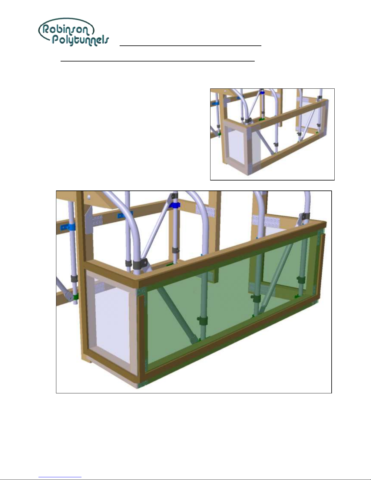
7. TIMBER SIDE RAIL (OPTION)
1Set the M25 fittings and H25 fittings 90cm above
the top of the Base Rail.
2Fix the timber rails along the sides of the
polytunnel, ensuring they are parallel with the
base rail.
3Continue around the corners, fixing to the posts
in the same way as the Base Rail.
Tip! Use the timber offcuts wherever they are long
enough.
4For each corner, cut a piece of timber to fit
between the base rail and the side rail.
5Fix this vertical timber between the base rail and the
side rail with a timber joint plate at each end using
30mm long twist nails.

8ft Wide “Poly-Pitch” Assembly Instructions
Copyright © Robinson Polytunnels 2014 13
8. ROLL UP CURTAIN (OPTION)
1Cut the 2m wide roll of polythene down the centre, to 1m wide. (This may have already been done for
you).
2Join the lengths of curtain tube together starting with
the plain-ended piece. Fix the tubes together with a
self-drill screw. Cut the last piece to length so that the
overall length of the tube is 30cm shorter than the gap
between the vertical corner timbers.
Tip! The curtain operates better if the gearbox is
positioned at the “low” end of the ‘tunnel.
3Slot the drive tube end into the curtain tube at
the end where you want to operate the
gearbox. Fix together with a self-drill screw,
65-70mm from the swage shoulder (to avoid
drilling into the square shaft).
4Slot a black PVC plug into the other end of the drive tube.
5Roll out the 1m wide polythene along the side of the polytunnel and lay
the drive tube on top, close to one edge.
6With the Spring Clips, clip the polythene to the drive tube at
approximately every 30cm, keeping the polythene as straight as
possible.
7Rest the drive tube on top of the base rail with
approximately 2cm gap between the end of the
drive tube and the vertical corner timber. Staple
the top edge of the polythene to the side rail,
flush with the top edge. At each end of the drive
tube, trim of the surplus polythene.

8ft Wide “Poly-Pitch” Assembly Instructions
Copyright © Robinson Polytunnels 2014 14
8Take up the slack in the polythene by rolling the drive tube into the
polythene. Slot the gearbox assembly onto the square shaft and slide
the guide tube into tube on the gearbox bracket.
9Hold the guide tube onto the inside faces of the base rail and side rail
and fix it to the base rail with an M8 x 50 coach screw.
10 With the gearbox handle, wind the
curtain up to the side rail. Fix the top
end of the guide tube to the side rail
with an M8 x 50 coach screw. Fit a
PVC plug into the top end of the
guide tube.
11 Check that the curtain rolls up parallel to the base rail and side rail and adjust the Spring Clips if
necessary.
12 Cut a notch out of the base rail where the gearbox touches to allow the
drive tube to rest directly on top of the base rail.
8ft Wide “Poly-Pitch” Assembly Instructions
Copyright © Robinson Polytunnels 2014 15
9. END PANELS & SIDE NETTING (INCLUDED WITH TIMBER SIDE RAIL OPTION)
1Cut a piece of polythene to fit over the panel at the side of the doorway and around the side of the
polytunnel by approximately 40cm (approximately 1m x 1.5m).
2Staple the polythene over the end frame, around the
side of the polytunnel to overlap the curtain.
3Unroll the net along the side of the polytunnel.
4Staple the net to the side rail, flush with the top edge.
Staple the net to the two vertical corner rails and to
the base rail.
5Batten over the net and end panels in the positions
shown.

8ft Wide “Poly-Pitch” Assembly Instructions
Copyright © Robinson Polytunnels 2014 16
10. FITTING THE ANTI HOT SPOT TAPE
1The Anti Hot Spot Tape is applied to the hoops of the polytunnel where
the polythene would touch.
2Starting just above the A20 fitting on the Foundation Tube, place the
Anti Hot Spot Tape on the outside face of the hoop. On the inner hoops
the tape should be central on the tube. On the end hoops the tape
should be on the “corner” of the tube.
Tip! Don’t fit the Anti Hot Spot Tape until you’re
ready to sheet –it may get damaged if the
weather is wet and windy.
3Tape over any sharp edges, bolt heads and metal faces that the polythene may come into contact with.

8ft Wide “Poly-Pitch” Assembly Instructions
Copyright © Robinson Polytunnels 2014 17
11. FITTING THE POLYTHENE –POLYTHENE TO BASE RAIL
1Unroll and unfold the polythene and drape it over the polytunnel framework with an equal amount over
each side and each end.
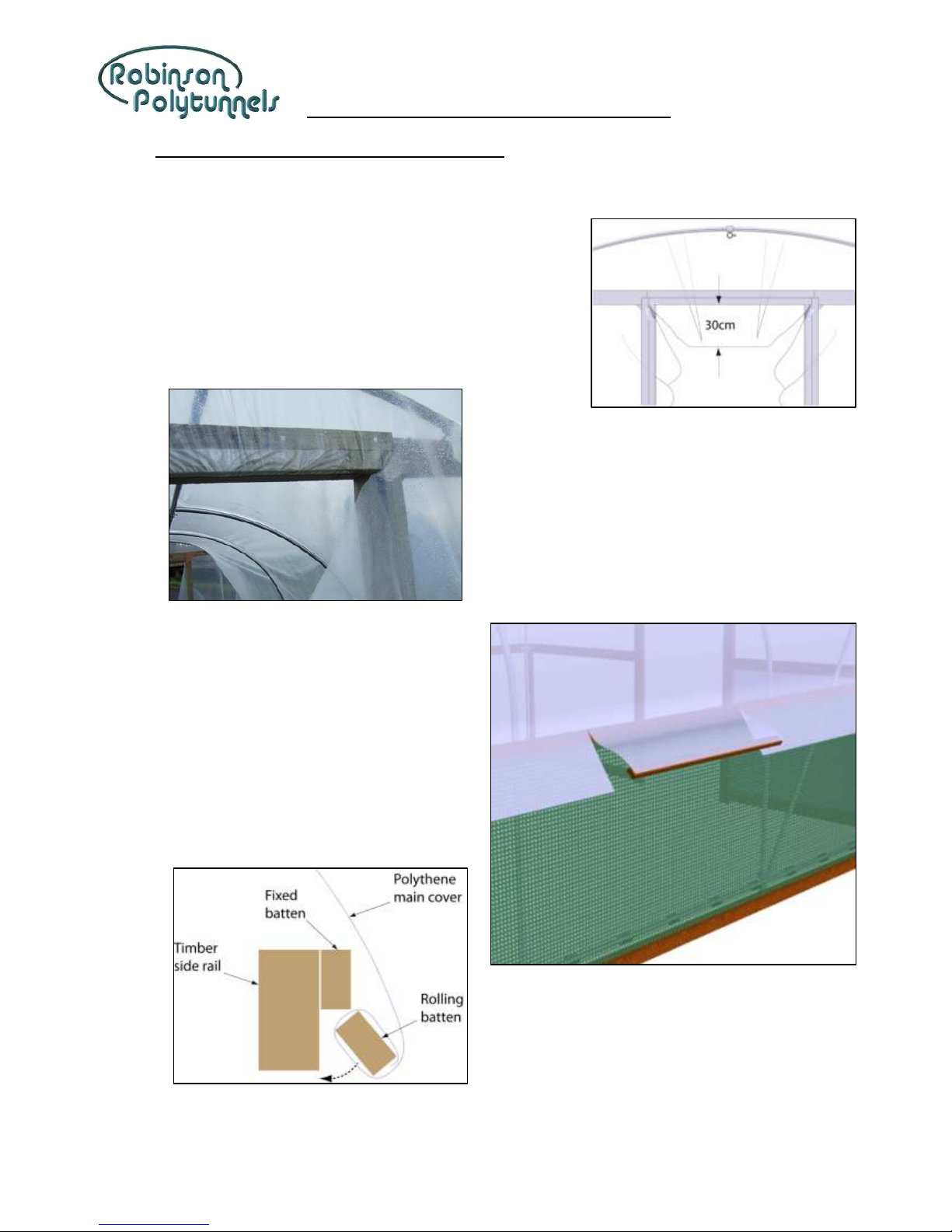
2Carefully slice the polythene diagonally from the top corners
of the doorway. Trim the bottom off the central flap so that it
hangs approximately 30cm below the door lintel.
3Cut a batten to fit in the rebate above each doorway
(approximately 86cm long).
4Place the batten underneath the flap of
polythene and roll the batten into the
polythene, up to the rebate. Nail the batten in
place. Note, it is preferable to have a couple of
small pleats in the flap of polythene.
5Repeat at the other end, PULLING THE
POLYTHENE AS TIGHT AS POSSIBLE.
6Starting at the centre of one side, batten the
polythene to the base rail. Hold the batten
under the edge of the polythene and carefully
cut the polythene in line with the ends of the
batten to create a flap, up to the bottom edge
of the base rail.
7Roll the batten into the polythene up to the
rebate and nail the batten to the base rail with
50mm long nails, at about 15cm apart.
8Do the same at the opposite side of the polytunnel but try to tension the polythene by levering the edge
of the batten against the rebate.
9Continue towards each end of the polytunnel, alternating between each side.
8ft Wide “Poly-Pitch” Assembly Instructions
Copyright © Robinson Polytunnels 2014 18
10 Continue around the corners, pulling the polythene towards to doorway.
11 Now fix the polythene to the door posts. The polythene
is pulled into the doorway and pleated. Trap the
polythene behind the batten as you nail the batten into
the rebate. Use approximately 9 nails 50mm long per
batten.
Tip! Fold the pleats “downwards” so that they
don’t collect rainwater. Lots of small pleats
are better than a few big pleats.
Tip! Pre-nail the battens so they’re ready to fix
the polythene quickly.
12 Trim off the surplus polythene in the doorway.
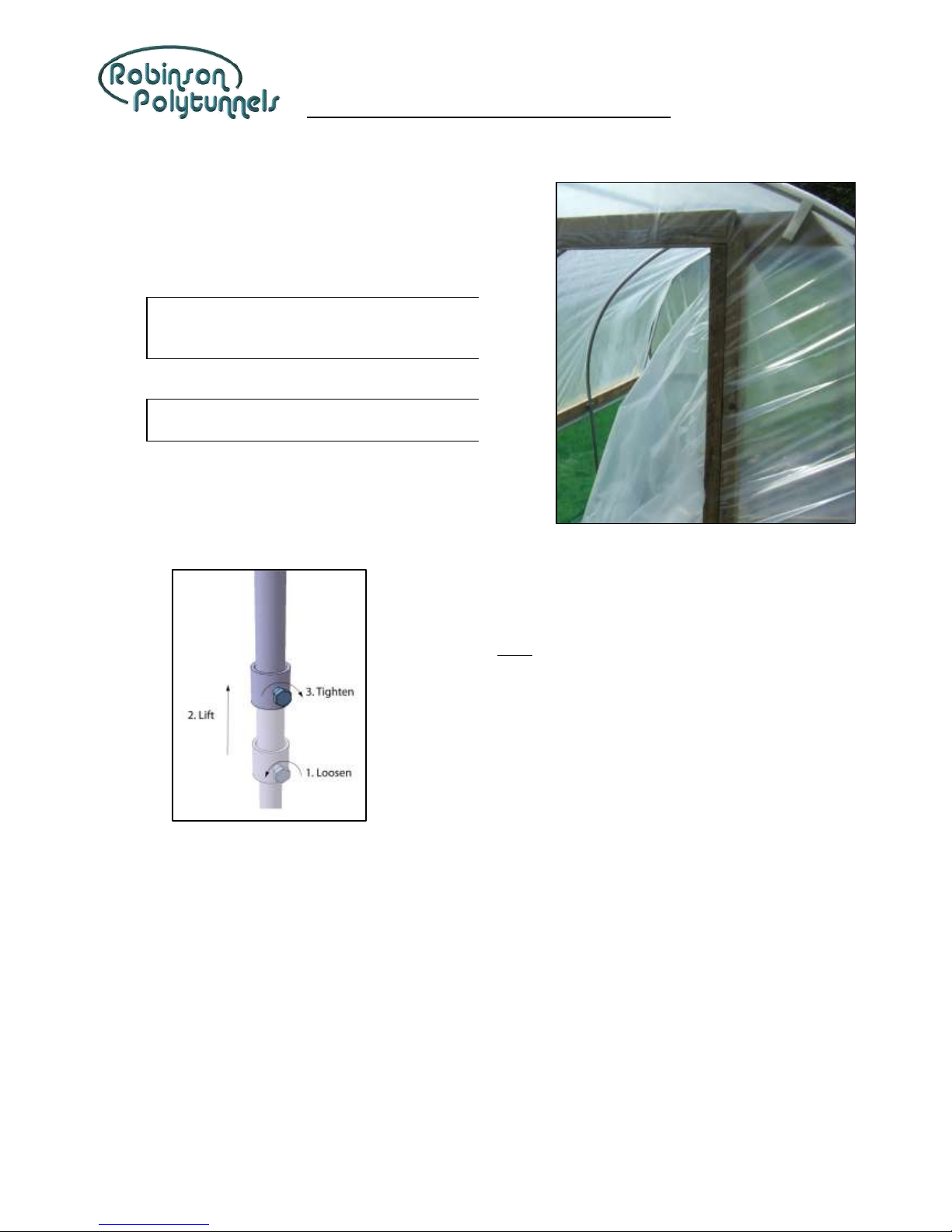
13 Raise the inner hoops to tension the polythene.
8ft Wide “Poly-Pitch” Assembly Instructions
Copyright © Robinson Polytunnels 2014 19
12. FITTING THE POLYTHENE –POLYTHENE TO SIDE RAIL
1Unroll and unfold the polythene and drape it over the polytunnel framework with an equal amount over
each side and each end.
2Carefully slice the polythene diagonally from the top corners
of the doorway. Trim the bottom off the central flap so that it
hangs approximately 30cm below the door lintel.
3Cut a batten to fit in the rebate above each doorway
(approximately 86cm long).
4Place the batten underneath the flap of
polythene and roll the batten into the
polythene, up to the rebate. Nail the batten in
place. Note, it is preferable to have a couple of
small pleats in the flap of polythene.
5Repeat at the other end, PULLING THE
POLYTHENE AS TIGHT AS POSSIBLE.
6Starting at the centre of one side, batten the
polythene to the side rail. Hold the batten
under the edge of the polythene and carefully
cut the polythene in line with the ends of the
batten to create a flap, up to the bottom edge
of the side rail.
7Roll the batten into the polythene up to the
rebate and nail the batten to the side rail with
50mm long nails, at about 15cm apart.
8Do the same at the opposite side of the
polytunnel but try to tension the polythene by
levering the edge of the batten against the
rebate.
9Continue towards each end of the polytunnel,
alternating between each side.

8ft Wide “Poly-Pitch” Assembly Instructions
Copyright © Robinson Polytunnels 2014 20
10 Continue around the corners, pulling the polythene towards to doorway.
11 Now fix the polythene to the door posts. The polythene
is pulled into the doorway and pleated. Trap the
polythene behind the batten as you nail the batten into
the rebate. Use 50mm long nails at about 10cm apart.
Tip! Fold the pleats “downwards” so that they
don’t collect rainwater. Lots of small pleats
are better than a few big pleats.
Tip! Pre-nail the battens so they’re ready to fix
the polythene quickly.
12 Trim off the surplus polythene in the doorway.
13 Raise the inner hoops to tension the polythene.
Table of contents
Popular Lawn And Garden Equipment manuals by other brands


Garden Oasis
Garden Oasis D71 M20513 Use & care guide

Billy Goat
Billy Goat SC181HEU owner's manual

Algreen Products
Algreen Products Madison quick start guide

greenhouse sensation
greenhouse sensation Hydropod Propagator Assembly and maintenance instructions

Atom
Atom 740 Operator owner's manual

Kooper
Kooper 5902380 User instructions