7
GB
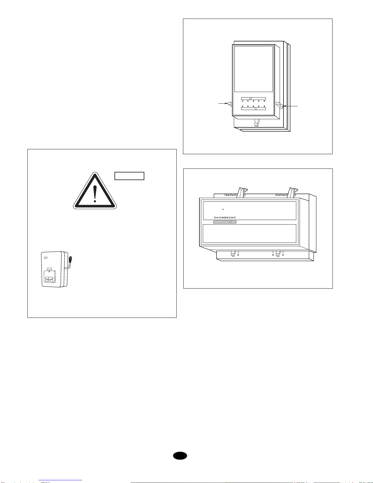
Compact installation of the units
The units are supplied prepared for connection of their
cooling circuits and electrically.
To install the units as a compact system, the outdoor ASAO
unit and the indoor ASAI one have to be joined through the
holesprovidedinthembythescrewsprovided.Thesewillbe
found in a bag inside the electrical box in the ASAO-60 and
in the indoor unit in the ASAI-25, 30 & 45.
The indoor and outdoor units are supplied with the cooling
circuit connections ready for soldering and to be intercon-
nected on the outside of the casing.
The ASAO/I-25 and ASAO/I-30 units have one sole circuit.
The ASAO/I-45 and ASAO/I-60 units has two circuits.
And the refrigerant load should be applied onsite.
Charge process
1 - Depressurise the units.
2 - Drain the refrigerant.
3 - Clean out with dry nitrogen.
4 - Solder the tubing under dry nitrogen inside the tubes.
5 - Forsolderinguselowmelting-pointrodswithaminimum
silver content of 5%.
6 - Fill with 2 kg. R-22 refrigerant to detect leaks.
7 - Drain off the refrigerant.
8 - Clean out with dry nitrogen.
9 - Create a vacuum down to 200 microns.
10- Put in the refrigerant, using scales or a calibrated
cylinder. Charge accuracy should be within 30 grams.
Theoutdoor unitisfittedwithplug-in pointsattheconnection
outlets for verification of pressure and temperature, Super-
heat and Sub-cooling. Check that these values are in the
order of 5°C.
Installation with separated units
Separation between the units
The length of connecting tubing should be kept down to the
minimum possible.
Maximumadmissibledistanceswiththecircuitandstandard
diameter tubes are:
Total length
of tubes
m
Maximum level
difference between units
m
1020
For greater lengths the installation must be made after a
previous project approved by our technical service.
This project may require modification of any of the following
elements:
- Tube dimensions.
- Refrigerant charge.
- Suction traps.
- Suction accumulator.
- Liquid solenoid valve.
In such cases the maximum lengths which can be recom-
mended are:
Cooling interconnections
When forming the tubing to join the two units special care
shouldbe takentokeepthetubes cleananddryevenbefore
installation. The following recommendations should be ob-
served:
1 - Use only copper tubing of refrigerant quality.
2 - Do not carry out outdoor work if it is raining.
3 - The ends of the tubes should be kept closed during the
installation.
4 -The dryer filters and compressor should not be left
exposed to the elements for more than one or two
minutes.
5 - For soldering use low melting-point rods with a minimum
silver content of 5%.
6 -During soldering and for as long as the tube stays hot, a
current of dry nitrogen should be kept up to avoid the
formationofoxideswhichcouldcausecontaminationand
blockage.
7 - For copper-copper unions stripper should not be used.
Units at same level, maximum length
Installation type
50m
Outdoor unit higher than indoor. Maximum
length and level difference. 50
m
Outdoor unit lower than indoor. Maximum
length and level difference. 15
m
PANEL
LOCKSCREW UPPER AND LOWER
UNITS LOCKSCREWS
(TWO ON EACH SIDE)
UPPER UNIT
(INDOOR)
LOWER UNIT
(OUTDOOR)