Roca DFK-75 AG User manual

1
DFK / DFO - 75 AG, 100 AG,120 AG
DBK / DBO - 75 AG, 100 AG, 120 AG
Ref: N-40105 1005M
EUnidades split cassette sólo frío y bomba de calor
Instrucciones de Instalación
○○○○○○○○○○○○○○○○○○○○○○○○○○○○○○○○○○○○○○○○○○○○○
7 - 14
GB Split cassette units, cool only and heat pump
Installation Instructions
○○○○○○○○○○○○○○○○○○○○○○○○○○○○○○○○○○○○○○○○○○○○
15 - 22
FUnités split cassette froid seul et réversible
Instructions d'Installation
○○○○○○○○○○○○○○○○○○○○○○○○○○○○○○○○○○○○○○○○○○○○
23 - 30
PUnidades split cassete do só frio e de bomba de calor
Instruções de Instalação
○○○○○○○○○○○○○○○○○○○○○○○○○○○○○○○○○○○○○○○○○○○○
31 - 38
IUnitá split tipo cassette solo freddo e a pompa di calore
Istruzioni per l'installazione
○○○○○○○○○○○○○○○○○○○○○○○○○○○○○○○○○○○○○○○○○○○○
39 - 46
DSplit-Kassettendegäte Nur Kühlen und Wärmepumpe
Hinweise zum Einbau
○○○○○○○○○○○○○○○○○○○○○○○○○○○○○○○○○○○○○○○○○○○○
47 - 54
NL Split-systeeminbouwcassetteenkelkoelingenwarmtempomp
Installatie-instructies
○○○○○○○○○○○○○○○○○○○○○○○○○○○○○○○○○○○○○○○○○○○○
55 - 62
NSplit cassette enheter bare avkjøling og varmepumpe
Installasjonsinstrukser
○○○○○○○○○○○○○○○○○○○○○○○○○○○○○○○○○○○○○○○○○○○○
63 - 70
Clima Roca York S.L. participa no Programa de Certificação EUROVENT.
Os produtos correspondem aos referidos no Directório EUROVENT de Produtos
Certificados, no programa AC1, AC2 eAC3.
Clima Roca York S.L. participa en el Programa de Certificación EUROVENT.
Los productos se corresponden con los relacionados en el Directorio EUROVENT de
Productos Certificados, en el programa AC1, AC2 y AC3.
Clima Roca York S.L. is participating in the EUROVENT Certification Program.
Products are as listed in the EUROVENT Directory of Certified Products, in the program
AC1, AC2 and AC3.
Clima Roca York S.L. participe au Programme de Certification EUROVENT.
Les produits figurent dans l'Annuaire EUROVENT des Produits Certifiés, dans le
programme AC1, AC2 et AC3.
Clima Roca York S.L. partecipa al Programma di Certificazione EUROVENT.
I prodotti interessati figurano nella Guida EUROVENT dei Prodotti Certificati, nel
programma AC1, AC2 eAC3.
Clima Roca York, S.L. ist am Zertifikationsprogramm EUROVENT beteiligt.
Die entsprechend gekennzeichneten Produkte sind im EUROVENT-Jahrbuch im
Programm AC1, AC2 und AC3 enthalten.
Clima Roca York, S.L. neemt deel aan het EUROVENT-certificatieprogramma.
De produkten zijn opgenomen in het EUROVENT-jaarboek van de gecertificeerde
produkten, in de programma AC1, AC2 en AC3.
Clima Roca York, S.L. deltar i EUROVENT sertifiseringsprogram.
ProdukteneeroppførtiEUROVENT'skatalogoversertifiserteprodukt,ikategorieAC1,
AC2 og AC3.
EUROVENT
CERTIFIED PERFORMANCE
CGM-97/013
ISO 14001
ER-0028/1991
ISO 9001

2

3
Unidad interior/Indoor unit/Unité intérieure/Unidade interior/Unità interna/Innengerät/Binnenunit/Innendørs enhet
Unidad exterior/Outdoor unit/Unité extérieure/Unidade exterior/Unità esterna/Anßengerät/Buitenunit/Utendørs enhet
Descripción de los componentes/Description of components/Description des composants/
Descrição dos componentes/Descripzione dei componenti/Beschreibung der Komponenten/
Beschrijving van de componenten/Beskrivelse av komponentene
98
8
10
1
2
3
4
5
6
7
8
MODE
SLEEP
FAN
SWING
LIGHT
AIR
T-ON
T-OFF
+°C -°C
ON/OFF

4
1Sistema de desagüe: Drenaje del agua resultante
por condensación en modo refrigeración
Drainsystem:Drainageofcondensedwater in cooling
mode
Système de drainage: Évacuation de l'eau des
condensats au mode de refroidissement
Sistema de desaguamento: Drenagem da água re-
sultante por condensação no modo de refrigeração
Sistema di scarico: Scarico della condensa che si
forma durante il funzionamento in modo raffred-
damento
Kondensatablauf: Ableitung des bei Kühlbetrieb
anfallenden Kondenswassers
Afvoersysteem: afvoer van het condenswater in de
functio koelen
Avløpssystem: Drenasje av kondensvann på
avkjølingsmodus
2Manguera de desagüe
Drain hose
Tuyau de drainage
Mangueira de desaguamento
Tubo di scarico
Kondensatschaluch
Afvoerslang
Avløpsslange
3Deflector o lama (salida de aire)
Deflector or slit (air outlet)
Déflecteur ou lame (sortie d'air)
Deflector ou lâmina (saída de ar)
Deflettore o lama (uscita d'aria)
Deflektor(Luftaustritt)
Uitblaasornament of lamel (luchtuitlaat)
Deflektor eller spejeld (luftavløp)
4Interconexión eléctrica y de refrigerante
Electrical and refrigerant interconnection
Interconnexion électrique et raccordement
frigorifique
Interligação eléctrica e de refrigerante
Collegamento elettrico e frigorifero
Elektrische und kältetechnische Verbindung
Onderlinge elektrische aansluiting en aansluiting
koelleidingen
Elektrik sammenkopling og av kjølemiddel
5Control remoto
Remote control
Commande à ditance
Controlo remoto
Comando a distanza
Fernbedienung
Afstandsbediening
Fjernkontroll
6Rejilla de entrada de aire
Air intake grid
Grille d'entrée d'air
Grelha de entrada de ar
Griglia di entrata aria
Lufteintrittsgitter
Luchtinlaatrooster
Luftinntaksrist
7Filtro anti-partículas
Antiparticle filter
Filtre anti-particules
Filtro antipartículas
Filtro
Luftfilter
Deeltjesfilter
Antipartikkelfilter
8Salida de aire
Air outlet
Sortie d'air
Saída de ar
Uscita d'aria
Luftaustritt
Luchtuitlaat
Luftavløp
9 Interconexión
Interconnection
Interconnexion
Interligação
Collegamento tra le unità
Verbindungsleitung
Onderlinge aansluiting
Sammenkopling
10 Entrada de aire
Air intake
Entrée d'air
Entrada de ar
Entrata d'aria
Lufteintritt
Luchtinlaat
Luftinntak

5
Diagrama de instalación/Installation diagram/Schéma de l'installation/Diagrama de instalação/
Schema d'installazione/Installationsschema/Installatieschema/Installasjonsskjema
> 500 > 500
> 300
> 2000
> 1000 > 1000
> 2000
Unidad interior/Indoor unit/Unité intérieure/Unidade interior/Unità interna/Innengerät/Binnenunit/Innendørs enhet
Unidad exterior/Outdoor unit/Unité extérieure/Unidade exterior/Unità esterna/Anßengerät/Buitenunit/Utendørs enhet
Fig. 2
Atención: El equipo de aire acondicionado ha de instalarlo personal cualificado acorde con este manual.
Attention: This air conditioning equipment must be installed by qualified personnel, in accordance with these instructions.
Attention: L'installation de l'appareil de climatisation doit être effectuée par un personnel qualifié et selon les instructions données dans ce manuel.
Atenção: O equipamento de ar condicionado tem de ser instalado por pessoal qualificado e de acordo com este manual.
Attenzione: Il climatizzatore deve essere installato da personale qualificato, seguendo le istruzioni riportate nel presente manuale.
Achtung: Die Klimaanlage muss von qualfiziertem Fachpersonal in Übereinstimmung mit den vorliegenden Hinweisen installiert werden.
Let op: De airconditioner dient door deskundig personeel en overeenkomstig deze handleiding geïnstalleerd te worden.
OBS: Dette luftklimatiseringsutstyret må installeres av kvalifiserte fagfolk i samsvar med foreliggende manual.
DFK/DBK 75 AG
DFK/DBK 100 AG, 120 AG
260
340
H (mm)
H
> 20 mm
> 1500 mm > 1500 mm
> 2300

6
DFK/DFO
75AG
DBK/DBO
120AG
7 000
6 020
-
-
2 750
-
20
12 000
10 350
12 500
10 750
4 750
4 400
20
1 180
4
47
840 x 840 x 240
950 x 950 x 60
30
6,5
230.1.50
60
950
840
412
75
R-407C
2,8
5/8"
3/8"
20
15
W
Frig.
W
kcal/h
W
W
A
m3/h
l/h
dB (A)
mm
mm
kg
kg
V.ph.Hz
dB (A)
mm
mm
mm
kg
kg
m
m
Especificaciones técnicas/Technical specifications/Spécifications techniques/Especificações
técnicas/Caratteristiche tecniche/Technische Mekmale/Technische specificaties
Unidad interior/Indoor unit/Unité intérieure/Unidade interior/Unità interna/Innengerät/Binnenunit/Innendørs enhet DFK/DBK
Unidad exterior/Outdoor unit/Unité extérieure/Unidade exterior/Unità esterna/Außengerät/Buitenunit/Utendørs enhet DFO/DBO
Modelos/Models/Modèles/Modelos/Modello/Modelle/Modellen/Modeller
Capacidad frigorífica/Cooling capacity/Puissance frigorifique/
Capacidade frigorífica/Potenza frigorifera/Kälteleistung/
Koelvermogen/Kjølekapasitet
Capacidad calorífica/Heating capacity/Puissance calorifique/
Capacidade calorífica/Potenza termica/Heisleistung/
Verwarmingsvermogen/Varmekapasitet
Consumo en frío/Consumption in cool/Consommation en froid/Consumo em frio/
Consumo in raffreddamento/Leistungsaufnahme Kühlen/Verbruik in koelen/
Forbruk på avkjøling
Consumo en calor/Consumption in heat/Consummation en chaud/Consumo em
calor/Consumo in riscaldamento/Leistungsaufnahme Heizen/Verbruik in
verwarming/Forbruk på oppvarming
Fusible/Fuse/Fusible/Fusível/Fusibile/Sicherung/Zekering/Sikring
Caudal de aire/Air flow/Débit d'air/Caudal de ar/Portata d'aria/
Luftdurchsatz/Luchtdebiet/Luftstrøm
Deshumidificación/Dehumidification/Déshumidification/Desumidificação/
Deumidificazione/Entfeuchtung/Luchtontvochtiging/Avfuktning
Presión sonora a 1m/Sound pressure at 1m/Pression acoustique à 1m/
Pressão sonora a 1m/Pressione sonora a 1m/Schalldruck in 1m
Abstand/Geluidsdruk op 1m/Lydtrykk på 1m avstand
Dimensiones cuerpo/Casing dimensions/Dimensions corps/Dimensões do
corpo/Dimensioni dell'unità/Abmessungen Gehäuse/Afmetingen frame/
Dimensjoner hoveddel
Dimensiones panel/Panel dimensions/ Dimensions panneau/Dimensões
do painel/Dimensioni del pannello/Abmessungen Verteilerplatte/
Afmetingen paneel/Dimensjoner panel
Peso cuerpo/Casing weight/Poids corps/Peso do corpo/Peso dell'unità/
Gewicht Gehäuse/Gewicht frame/Vekt hoveddel
Peso panel/Panel weight/Poids panneau/Peso do painel/Peso del
pannello/Gewicht Verteilerplatte/ Gewicht paneel/Vekt panel
Alimentación eléctrica/Power supply/Alimentation électrique/
Alimentação eléctrica/Alimentazione elettrica/Elektr. Anschluss/
Voedingsspanning/Elektrisk mating
Nivel sonoro/Sound level/Niveau sonore/Nível sonoro/Livello sonoro/
Schalldruck/Geluidsniveau/Lydtrykk
Ancho/Width/Largeur/Largura/Larghezza/Breite/Breedte/Bredde
Alto/Height/Hauteur/Altura/Altezza/Höhe/Hoogte/Høyde
Profundidad/Depth/Prodondeur/Profundidade/Profondità/Tiefe/Diepte/
Dybde
Peso/Weight/Poids/Peso/Peso/Gewicht/Gewicht/Vekt
Refrigerante/Refrigerant/Réfrigérant/Refrigerante/Refrigerante/
Kältemittel/Koelmiddel/Kjølemiddel
Carga (para 5m tubería)/Charge (for 5 m. tubing)/Charge (pour 5m
tuyauterie)/Carga (para 5m de tubagem)/Carica (per 5 metri di tubo)/
Kältemittelmenge (für 5m Leitung)/Vulling (per 5 m leiding)/Ladning (for
5 m rørledning)
Diámetro tubo gas/Gas pipe diameter/Diamètre tuyau gaz/Diâmetro do tubo
de gás/Diametro tubo gas/Durchmesser Gasleitung/Doorsnede gasleiding/
Diameter gassrør
Diámetro tubo líquido/Liquid pipe diameter/Diamètre tuyau gaz/Diâmetro do
tubo de líquido/Diametro tubo liquido/Durchmesser Flüssigkeitsleitung/
Doorsnede vloeistofleiding/Diameter væskerør
Máxima longitud linea frigorífica/Maximum length cooling line/Lorgueur
maximale ligne frigorifique/Máximo comprimento da linha frigorífica/
Massimo lunghezza linea frigorifera/Maximale Kältemittelleitung/
Maximale lengte koellijn/Maksimal lengde kjølelinje
Máximo desnivel/Maximum drop/Dénivellement maximal/Máximo
desnível/Massimo deslivello/Maximaler Höhenunterschied/Maximale
niveauverschil/Maksimal høydeforskjell
DFK/DFO
100AG
DFK/DFO
120AG
DBK/DBO
100AG
DBK/DBO
75AG
10 000
8 600
-
-
4 300
-
20
12 000
10 350
-
-
4 750
-
20
7 000
6 020
7 500
6 450
2 750
2 750
20
10 000
8 600
10 500
9 030
4 300
4 400
20
75AG
1 860
6
54
840 x 840 x 320
950 x 950 x 60
38
6,5
100AG
1 860
7
53
840 x 840 x 320
950 x 950 x 60
38
6,5
120AG
400.3.50
62
950
1 250
412
112
R-407C
3,4
3/4"
1/2"
20
15
400.3.50
63
950
1 250
412
112
R-407C
3,8
3/4"
1/2"
30
20
75AG 100AG 120AG

7
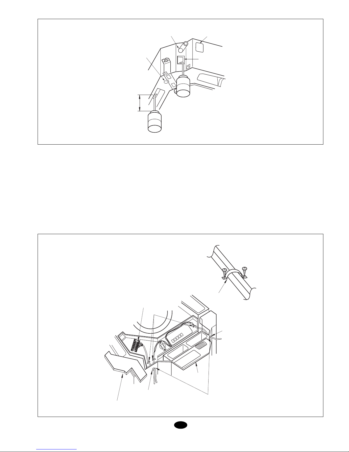
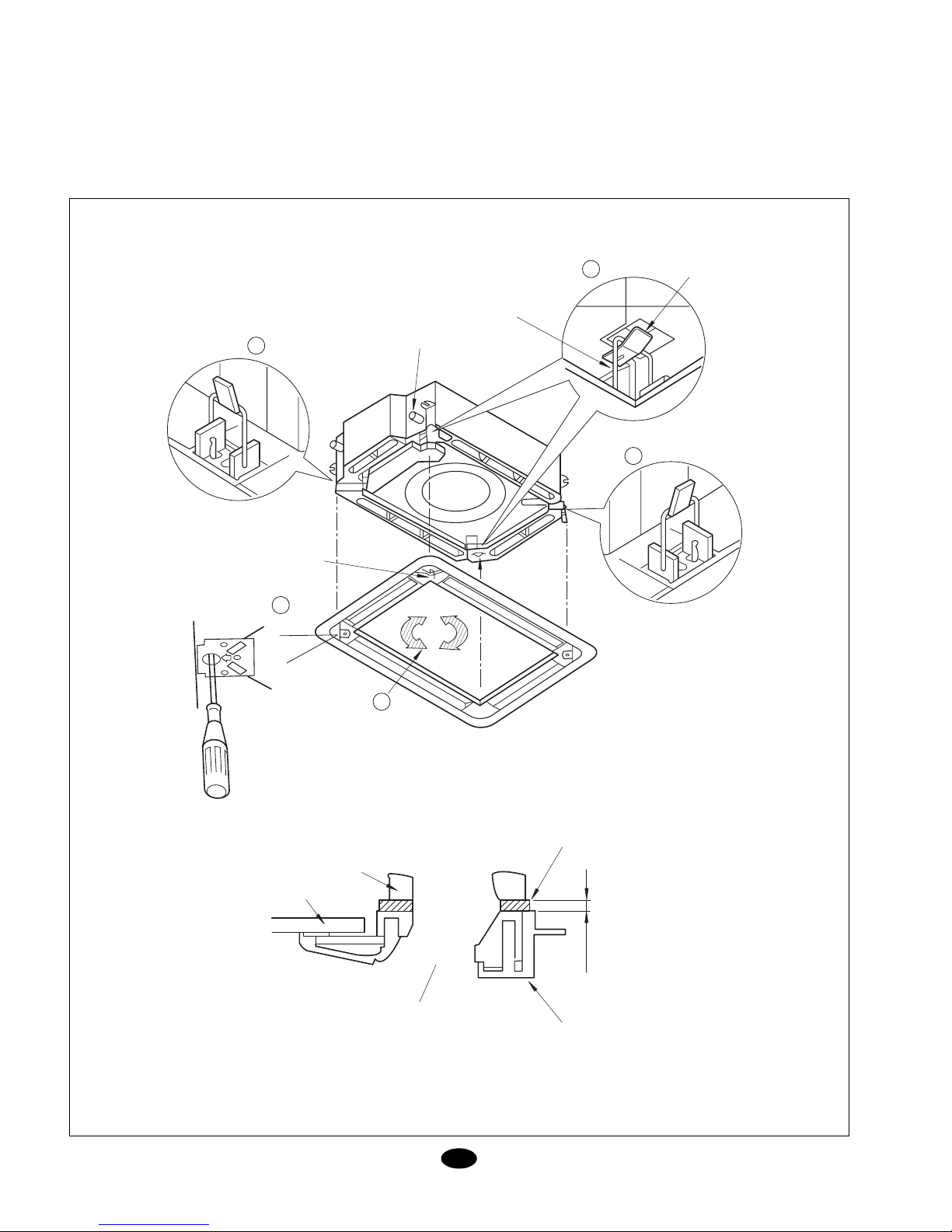
Instalación de la unidad inte-
rior (Fig. 4 y 4 bis)
1. Ubique la unidad interior.
- Sujete el soporte a los tornillos de suje-
ción. Asegúrese de que están bien fija-
dos y utilice tuercas y arandelas tanto en
la parte superior como inferior del sopor-
te. La plaqueta de sujeción o fijadores (1)
evitará el desprendimiento de las
arandelas.
- Utilice la plantilla (2) para saber las di-
mensiones de la apertura en el techo.
- Tanto el centro de la apertura en el te-
cho, como el centro de la máquina vie-
nen indicados en la plantilla adjuntada al
equipo.
- Fije la plantilla a la unidad interior con los
tornillos (3) x 3.
2.Ubique la unidad en su correcta posición
para la instalación.
3.Compruebe que la unidad está colocada
horizontalmente (con nivel).
- La unidad interior está equipada con una
bomba y una boya en cada una de las
cuatro esquinas. Compruebe su correcta
colocación con un nivel o el tubo de vinilo.
(Si la unidad se coloca en contra del flujo
de agua condensada, la boya no actuará
correctamente y podría causar derrame
de agua).
4.Retire el fijador de las arandelas (1) y
enrosque la tuerca superior.
5.Retire la plantilla de instalación (2).
E
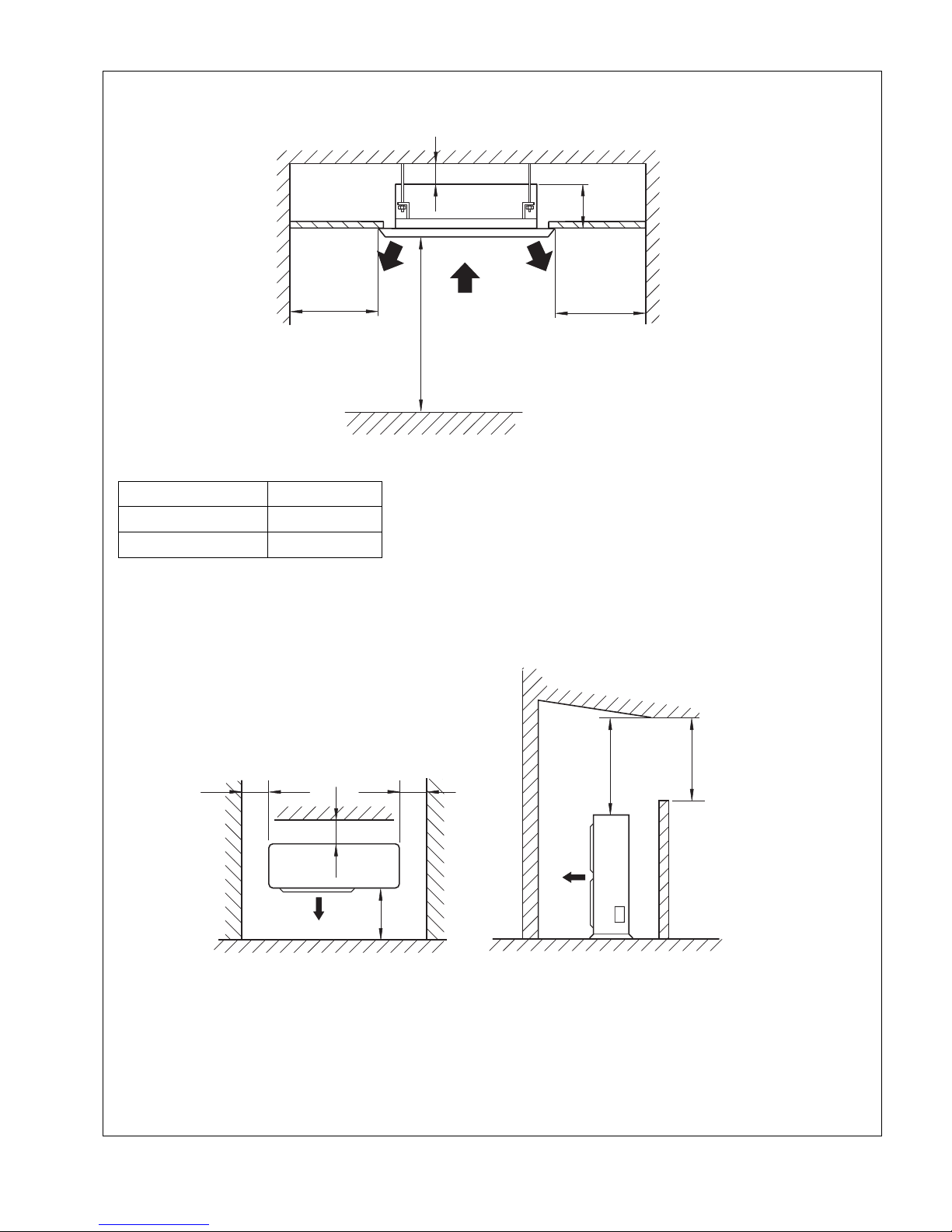
Ubicación unidad interior
1. No coloque objetos cerca de la salida
de aire, para que éste pueda llegar a
toda la habitación.
2. Asegúrese de instalar la unidad interior
firme y horizontalmente.
3. Seleccione un lugar que pueda aguan-
tar 4 veces el peso de la unidad a efec-
tos de reducir el nivel sonoro ocasiona-
do por las vibraciones.
4. Seleccione un lugar donde sea fácil ubi-
car el desagüe y los más cerca posible
de la unidad exterior.
5. Asegúrese que hay suficiente espacio
libre para poder llevar a cabo cualquier
actividad de mantenimiento.
6. Asegúrese que el sistema de suspen-
sión pueda aguantar 4 veces el peso de
la unidad, para evitar la saturación
(compresión permanente).
Nota:
1. Mantenga una distancia prudencial con
la cocina.
2. No debe instalarse en lavanderías.
Apertura del techo y tornillos
de suspensión (M10) (Fig. 3)
Atención: Atornille las tuercas en preven-
ción de la caída de la unidad.
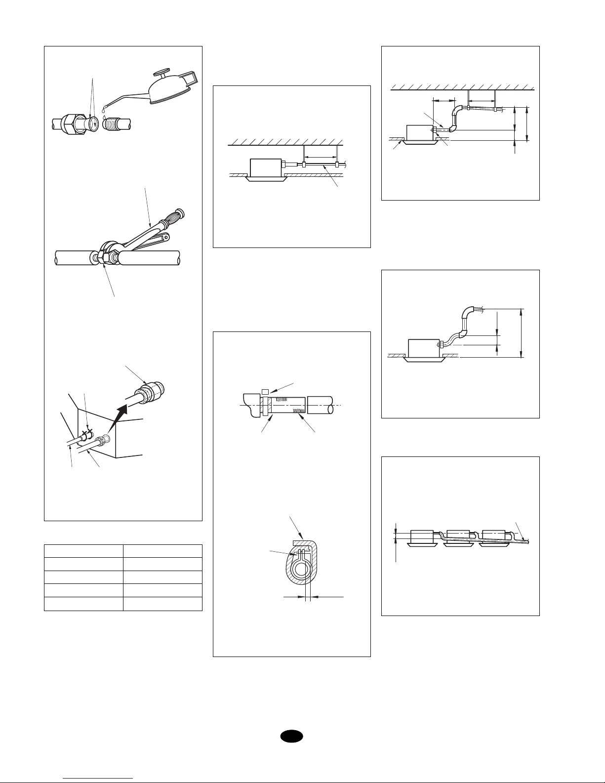
Conexiones frigoríficas (Fig. 5)
- Asegúrese de utilizar las dos llaves al
mismo tiempo, como se muestra en los
dibujos siguientes, al conectar y desco-
nectar las tuberías de refrigeración.
- Refiérase a la tabla 1 para determinar la
fuerza correcta a aplicar en el apretado
de las tuercas. (Un apretado excesivo
podría provocar fugas de gas).
- Cuando conecte las tuberías cubra tanto
el lado interior como el lado exterior del
tubo con aceite de máquinas de refrige-
ración y apriételas inicialmente a mano 3
o 4 vueltas.
- Revise la conexión de las tuberías en pre-
visión de fugas de gas, entonces aíslelo
como se muestra a continuación.
- Utilice la masilla selladora (11) para ais-
lar la conexión del aislamiento (8).
- En instalaciones que se supere la distan-
cia de 10 metros se ha de añadir 30g por
metro que superen de estos 10m, tenien-
do en cuenta que no se puede superar
Fig. 3 Fig. 4
Fig. 4 bis
160
VISTO DESDE “A”
SUJECCIÓN
TECHO
SOPORTE DE
SUJECIÓN
APRETAR CON
DOBLE TUERCA
ARANDELA (INCLUIDA)
ESPÁRRAGO M10
TUBO DE
VINILO
NIVEL DE
AGUA
780 SUJECCIÓN
840 UNIDAD INTERIOR
890 APERTURA TECHO
950 PANEL FRONTAL
780 SUJECCIÓN
840 UNIDAD INTERIOR
890 APERTURA TECHO
950 PANEL FRONTAL
A
FIJADOR DE
ARANDELA (1)
INSERTAR
TORNILLOS (3)
CENTRO DE LA
APERTURA EN
EL TECHO
PLANTILLA DE
INSTALACIÓN (2)
TORNILLOS (3)
FIJE LOS TORNILLOS
EN LAS ESQUINAS DEL
SISTEMA DE DRENAJE
950
> 20

8
los 25 metros máximos permitidos de dis-
tancia.
- Si la manguera no tiene la suficiente
pendiente, añada una pequeña eleva-
ción.
- Para evitar que la manguera se despren-
da coloque las sujeciones como míni-
mo a 1-1,5 m entre sí.
mm de la unidad y con el ángulo correc-
to.
E
Fig. 5
Diámetro
3/8"
1/2"
5/8"
3/4"
Fuerza
30 a 40 N. m
45 a 50 N. m
60 a 65 N. m
70 a 75 N. m
Tabla 1
Manguera de desagüe
(Figs. 6 y 7)
1. Instalación de la manguera de desagüe.
- El diámetro de la manguera de desagüe
ha de ser mayor o igual al diámetro del
tubo de salida (tubo de vinilo 25 mm de
diámetro exterior).
- Mantenga la manguera con una ligera
pendiente del 1% como mínimo para
prevenir bolsas de aire en el interior.
- Utilice la manguera (1) y la abrazadera
(2).Insértela por encima de al zona gris.
Enrosque la abrazadera hasta que la
cabeza salga unos 4 mm.
- Utilice el aislante de mayor tamaño para
cubrir el sistema de desagüe.
- Aislé el desagüe dentro de la habitación.
Fig. 8
Precauciones para la eleva-
ción de la manguera (Fig. 8)
- Instale la elevación a una altura inferior
de 280 mm.
- Instale la elevación como máximo a 300
Fig. 7
Fig. 6
Atención: (Fig. 9 y 9 bis)
- La inclinación de la manguera incluida,
podría ser 75mm o menos sin que ésta
tenga que realizar ninguna fuerza adicio-
nal.
Fig. 9
- Siga el consejo siguiente para instalar un
sistema múltiple.
Fig. 9 bis
2. Después de terminal la instalación com-
pruebe que el agua fluye correctamen-
te.
- Añada aproximadamente 600cm3de
agua al sistema de desagüe através del
agujero de inspección.Vierta el agua len-
tamente y compruebe el flujo.
- Cuando termine la instalación eléctrica
compruebe el flujo del desagüe en modo
frío.
< 500 mm
< 75 mm
CUBRA CON ACEITE
DE REFRIGERACION
LLAVE FIJA
TUERCA
MASILLA
AISLANTE (11)
AISLAMIENTO (8)
ABRAZADERA (4) x 4
GASLIQUIDO
CINTA GRIS MANGUERA (1)
ABRAZADERA (2)
< 4 mm
ABRAZADERA (2)
SELLANTE (10)
JUNTA
1 a 1,5 m
TECHO
SALIDA DE
DESAGÜE
< 300 mm
< 280 mm
< 500 mm
< 200 mm
ELEVACIÓN DEL
DESAGÜE
< 100 mm
SITEMA MULTIPLE
CONVERGENTE TIPO T
DESNIVEL 1%
1 a 1,5 m

9
E
Método de adición de agua (Fig.10)
Conexionado eléctrico
Atención: Antes de acceder a los termina-
les desconecte la fuente de alimentación.
- Todos los accesorios y materiales sumi-
nistrados con el equipo cumplen la nor-
mativa local.
- Para el conexionado eléctrico diríjase al
esquema eléctrico en el interior de la uni-
dad.
- El conexionado eléctrico ha de realizarlo
personal autorizado.
- Ha de instalarse un interruptor diferencial
capaz de desconectar todo el sistema.
- La conexión a tierra ha de ser la correc-
ta.
- La conexión eléctrica ha de cumplir la
normativa vigente.
- El interruptor instalado no debe sobrepa-
sar los 30mA.
- Si el cable de alimentación se dañase,
ha de reemplazarse por uno original y
mediante personal cualificado.
Conexiones de la unidad y el controla-
dor (Fig. 11)
- Retire la tapa (1) e inserte los cables den-
tro através de la goma protectora I y co-
néctelo acorde con el esquema eléctrico
del interior de la unidad. Sujételo con la
abrazadera.
- Retire la tapa (2) e inserte los cables den-
tro através de la goma protectora II y co-
néctelo al controlador.
- Cubra los cables con aislante.
- Después del cableado, sujételo con las
abrazaderas y coloque las tapas 1 y 2.
- Para sistemas frío/calor: Conecte los 5
terminales correctamente.
- Para sistemas solo frío: Conecte los 3
terminales correctamente.
Fig. 10
Fig. 11
MANGUERA DE
DESAGÜE
SALIDA DE SERVICIO
DE DESAGÜE
ADICION DE AGUA
A TRAVES DEL AGUJERO
DE INSPECCION
100 mm
ORIFICIO
DE INSPECCION
TAPA DE
SERVICIO
GOMA
PROTECTORA 2
TAPA DE CAJA DE
CONTROL 2
GOMA
PROTECTORA 1
TAPA DE CAJA DE CONTROL 1
SELLE AQUI PARA EVITAR FUGAS
TERMINALES DE CONEXION
3 - PARA FRIO / CALOR
5 - PARA SOLO FRIO
ABRAZADERA

10 E
Asegúrese de conectar los
polos correctos en ambas uni-
dades (Fig. 12)
Instalación del panel.
1. Coloque el panel en la unidad interior,
colocando la esquina del motor de la-
mas con la esquina de tuberías de la
unidad interior.
2. Instalación del panel decorativo:
(1) Cuelgue la trabilla, que está en el lado
contrario del motor de lamas del panel
decorativo, temporalmente del soporte
para ello habilitado. (2 Posiciones).
(2) Cuelgue también temporalmente las dos
trabillas restantes. Tenga cuidado y evi-
te que el cable del motor de lamas se
enganche en con el material sellante.
(3) Atornille los 4 tornillos hexagonales de
la parte derecha bajo las trabillas aprox.
(El panel subirá 15 mm).
(4) Ajuste el panel girándolo en los senti-
dos descritos en la figura. A efectos de
cubrir por completo la apertura del te-
cho.
(5) Apriete los tornillos hasta que la distan-
cia entre la unidad interior y el panel se
reduzca a unos 5 - 8 mm.
Fig. 12
SOPORTE
TRABILLA
1
3
4
MOTOR DE LAMAS
TUBERIAS
2
2
5 ~ 8 mm
PANEL FRONTAL
SALIDA DE AIRE
UNIDAD INTERIOR
TECHO
MATERIAL SELLANTE

11
E
Precauciones
1.Un atornillamiento incorrecto puede cau-
sar problemas como los de la figura 13.
Fig. 13
2.Si hay algún hueco entre el techo y el
panel frontal después del atornillado, re-
ajuste la altura de la unidad interior como
muestra la figura 14.
Ajuste la altura de la unidad interior através de las
aperturas en las esquinas del panel frontal es posible
si la unidad interior está nivelada. Esto no afectará a
las conexiones.
* Después de fijar la unidad asegúrese que no hay
espacio entre la máquina y el techo.
3.Conexión del panel frontal.
Fig. 14
(6) Una los 2 conectores del panel frontal con lo de la unidad.
Fig. 15
Selección de ubicación para la
unidad exterior
- Seleccione un lugar que satisfaga las si-
guientes condiciones y las impuestas por
el cliente.
- Seleccione un lugar donde el aire y el
ruido emitidos por la unidad no moleste a
los vecinos.
- Seleccione un lugar de elevada ventilación.
- La entrada y salida de aire no pueden
estar obstruidas.
- Instalar en un lugar lo suficientemente
fuerte para aguantar el peso y las vibra-
ciones de la unidad.
- No puede haber peligro de gases infla-
mables o corrosivos.
- Asegúrese que la instalación sigue las
distancias recomendadas en el diagrama
de dimensiones de instalación.
Instalación de la unidad exte-
rior
1. Instale la unidad con tornillos de M10 o
más, firmemente y en posición vertical.
2. No instale la unidad en el tejado.
3. Asegúrese que no haya vibraciones
para evitar ruidos, para ello añada
arandelas de goma.
4. Evacue el agua de condensados a un
lugar apropiado.
5. Fije el sistema de desagüe utilizando el
orificio de la parte inferior de la unidad
exterior.
Purgado y test de fugas
1. Una las tuberías de gas y líquido con
su válvula correspondiente.
2. Apriete las tuerca de forma correcta.
3. Retire las tuercas de protección de la
unidad exterior, tanto de la tubería de
líquido, la de gas como la válvula de ser-
vicio.
4. Libere la válvula de líquido con una lla-
ve hexagonal.
5. Empuje la válvula de chequeo de pre-
sión pulsando en su centro.
FUGA DE AIRE
FUGA DE AIRE
DEL TECHO
FUGA DE AGUA DE CONDENSACION
NO SE PERMITEN ESPACIOS
UNIDAD
INTERIOR PANEL
FRONTAL
UNIDAD
INTERIOR PANEL
FRONTAL
572 mm
378 mm

12
6. Deje de apretar tan pronto vea salir re-
frigerante por ella, y vuelva a colocar la
tuerca del puerto de servicio.
7. Abra las dos válvulas completamente,
tanto la de gas como la de líquido. (Fig.
16)
8. Apriete las tuercas de las válvulas.
9. Compruebe las posibles fugas de todo
el circuito con jabón líquido o un detec-
tor de fugas.
ROSCA DE
PRESION
VALVULA DE
LIQUIDO
VALVULA DE
GAS
VALVULA DE
SERVICIO
Fig. 16
Vacío del circuito
Es muy recomendable realizar el vacío del
circuito para su correcto funcionamiento.
Esto descargaría los posibles restos de gas
y humedad del circuito. Véase Fig. 17.
Conexión eléctrica
(1) Lea la placa de características cuida-
dosamente. Realice la conexión de
acuerdo con el esquema eléctrico del
interior.
(2) Se ha de instalar algún tipo de interrup-
tor capaz de desconectar todo el equi-
po.
(3) Conécte la conexión a tierra.
(4) Todo el conexionado eléctrico ha de rea-
lizarlo personal cualificado acorde con
el esquema eléctrico. Un conexionado
erróneo podría causar fuego o descar-
gas eléctricas.
Conexión de la alimentación
eléctrica
(1) Retire la tapa frontal (Fig. 18).
(2) Habilite la entrada de cables y protéjala
con el protector de goma.
(3) Pase todos los cables através de este
protector.
(4) Conecte la unidad exterior acorde con
el esquema eléctrico.
(5) Sujete los cables con las abrazaderas y
bridas.
Atención
(1) Conecte el tierra firmemente.
(2) Conecte los cables firmemente.
(3) No fuerce los conectores.
(4) Conexión de alimentación:
* Equipos solo frío: - Conecte la mangue-
ra de 3 cables a los terminales L, N1 y
tierra.
- Conecte la manguera de 5 cables a los
terminales L1, L2, L3, N y tierra.
* Equipo frío/calor: - Conecte la mangue-
ra de 5 cables a los terminales L1, L2,
L3, N y tierra.
(5) Conecte el resto de cables adecuada-
mente.
- No tire del cable cuando vaya a suje-
tarlos con las abrazaderas y bridas.
- No deje el cable demasiado suelto en
la unidad exterior.
Fig. 17
Fig. 18
E
MANOMETRO
TUERCA
BOMBA DE
VACIO
TUBO DE
GAS
TUBO DE
LIQUIDO
CONEXION
ELECTRICA
TAPA
LATERAL
TAPA
FRONTAL
BRIDAS
ENTRADA
CABLES
CABLES
L1 L2 L3 N L N L1 L2 L3 N
5 CABLES
RED
ELECTRICA
3 CABLES
UNIDAD
INTERIOR
5 CABLES
RED
ELECTRICA
CONEXION ELECTRICA
DFO 100, 120 DBO 100, 120
L N L1 N1
3 CABLES
RED
ELECTRICA
3 CABLES
UNIDAD
INTERIOR
DFO, DBO 75
Sección cables DFK y DBK
Interconexión
mm2
Fusible
3 x 2,5
Suministro eléctrico
Tamaños
Potencia
DFK, DFO
75
DFK, DFO
100, 120
DBK, DBO
75
DBK, DBO
100, 120
3 x 2,5 5 x 2,5 5 x 2,5
mm2
Control mm2
A
3 x 1,5 3 x 1,5 3 x 1,5 -
6 x 1,5 9 x 1,5 8 x 1,5 11 x 1,5
16 16 10 10

13
E
Fig. 19
Rutina de test y chequeo
post-instalación
Operación de Test (Fig. 19)
1. Antes de test:
(1) No conecte el equipo hasta que esté
complemente instalado.
(2) La conexión eléctrica ha de ser co-
rrecta y segura.
(3) Las válvulas han de estar abiertas.
(4) El equipo ha de estar libre de impu-
rezas.
2. Método de la operación de test
(1) Conecte el equipo y pulse el botón
ON/OFF del mando a distancia.
(2) Pulse el botón MODE para compro-
Bomba de calor
Sólo frío
ALIMENTACION ELECTRICA 3 HILOS
(L,N, ) 230V/1Ph/50Hz (SUMINISTRADO)
DB 75 AG DBO 75 AG
N
L1
UNIDAD INTERIOR CONECTOR MANIOBRA
5 HILOS, SUMINISTRADO CONECTOR MANIOBRA
3 HILOS, SUMINISTRADO
UNIDAD EXTERIOR
3 HILOS
230V/1Ph/50Hz
ALIMENTACION ELECTRICA
230V/1Ph/50Hz
NL
DB 100 AG
DB 120 AG DBO 100 AG
DBO 120 AG N
L1
L3
L2
UNIDAD INTERIOR
CONECTOR MANIOBRA
3 HILOS, SUMINISTRADO
CONECTOR MANIOBRA
4 HILOS, SUMINISTRADO
UNIDAD EXTERIOR
5 HILOS
400V/3Ph/50Hz
ALIMENTACION ELECTRICA 3 HILOS
(L,N, ) 230V/1Ph/50Hz (SUMINISTRADO)
DF 75 AG DFO 75 AG
UNIDAD INTERIOR CONECTOR MANIOBRA
4 HILOS, SUMINISTRADO CONECTOR MANIOBRA
2 HILOS, SUMINISTRADO
UNIDAD EXTERIOR
N
L1
3 HILOS
230V/1Ph/50Hz
ALIMENTACION ELECTRICA 3 HILOS
(L,N, ) 230V/1Ph/50Hz (SUMINISTRADO)
DF 100 AG
DF 120 AG DFO 100 AG
DFO 120 AG
N
L1
L3
L2
UNIDAD INTERIOR CONECTOR MANIOBRA
4 HILOS, SUMINISTRADO
CONECTOR MANIOBRA
5 HILOS, SUMINISTRADO
UNIDAD EXTERIOR
5 HILOS
400V/3Ph/50Hz
bar que funcionan los tres modos for-
zados:
FRIO, CALOR, DESHUMIDIFICACIÓN.
3. Método de emergencia.
Cuando no se pueda utilizar el mando a
distancia, opere de la siguiente forma:
* Con la máquina parada pulse AUTO
para activarla.El equipo funcionará en
el modo que corresponda.
* Con la máquina en marcha pulse
AUTO para apagarla.
Nota: El modo TEST es solamente para
realizar pruebas. No utilizar como modo de
funcionamiento normal.
Conexiónes eléctricas

14
Datos y medidas susceptibles de variación sin previo aviso.
E
Comprobar
¿ Está fijado firmemente?
¿ Se ha hecho un chequeo de fugas?
¿ Es suficiente el aislamiento de calor?
¿ Es correcto el drenaje?
¿ La tensión de alimentación es la que marca la placa eléctrica?
¿ Es correcta y segura la instalación realizada?
¿ La conexión a tierra es correcta?
¿ Es el cable de alimentación especificado?
¿ Están cubiertas las entradas y salidas de aire?
¿ Es la carga de refrigerante acorde con la distancia de los tubos?
Posible mal funcionamiento
La unidad podría caerse, mover o emitir ruido
Podría generar una capacidad refrigerante insuficiente
Podría generar condensación y calado
Podría dañar el equipo
Podría generarse descargas eléctricas
Podría dañar el equipo
Podría disminuir la capacidad de refrigeración
La capacidad del refrigerante no es la óptima
Su producto está marcado con este símbolo. Esto significa que al final de su vida útil no debe mezclarse
con el resto de residuos domésticos no clasificados, sino que su eliminación debe realizarse de acuerdo
con la normativa local y nacional pertinente, de forma correcta y respetuosa con el medio ambiente.
El desmantelamiento del acondicionador de aire, así como el tratamiento del refrigerante, aceite y otros
componentes, debe ser efectuado por un instalador competente de acuerdo con la legislación aplicable.
Contacte con las autoridades locales para obtener más información.
ATENCIÓN
Comprobar después de instalar

15
GB
Fig. 3 Fig. 4
Fig. 4 bis
Locating indoor unit
1. Do not place objects near the air dis-
charge so the air may be distributed
throughout the room.
2. Make sure the indoor unit is installed
firmly and in horizontal position.
3. Select a location that can support 4
times the weight of the unit so as to de-
crease noise level due to vibration.
4. Select a location where it is easy to in-
stall the drain, and as close to the out-
door unit as possible.
5. Make sure there is sufficient clearance
for all maintenance servicing.
6. Make sure the suspension system can
support 4 times the weight of the unit so
as to avoid saturation (permanent com-
pression).
Note:
1. Keep a reasonable distance from the
kitchen.
2. This equipment should not be installed
in laundry rooms.
Opening in the ceiling and sus-
pension bolts (M10) (Fig. 3)
Installing the indoor unit (Fig. 4
and 4a)
1. Locate the indoor unit.
- Fasten the support to the fastening bolts.
Make sure they are firm and use nuts
and washers on both top and bottom of
the support. The fastening plate or fas-
teners (1) avoid movement of the wash-
ers.
- Use template (2) to establish the dimen-
sions of the opening in the ceiling.
- The centre of both the opening in the
ceiling as well as the unit are indicated
on the template supplied with this equip-
ment.
- Fasten the template to the indoor unit
with screws (3) x 3.
2. Locate the unit in correct position for in-
stallation.
3. Make sure the unit is in horizontal posi-
tion (with a level).
- The indoor unit is equipped with a pump
and float at each one of the four corners.
Check correct positioning with a level or
vinyl pipe. (If the unit is installed con-
trary to condensed water flow, the float
will not operate correctly and could
cause water spilling.)
4. Remove the fastener from washers (1)
and screw in the top nut.
5. Remove the installation template (2).
Attention: Tighten the nuts to make sure
the unit does not fall.
Cooling connections (Fig. 5)
- Use both wrenches at the same time, as
shown in the following illustrations, to con-
nect and disconnect the cooling pipes.
- See Table 1 to determine correct torque
to be applied to the nuts. (Tightening in
excess could cause gas leaks.)
- When connecting pipes, cover both the
outer as well as inner sides of the pipes
with cooling machine oil, and tighten them
manually 3 or 4 turns.
- Check pipe connections for gas leaks, and
lay them as indicated below.
- Use the sealing filler (11) to insulate con-
nection (8).
- On installations with a length of over 10
metres, add 30 g. per each metre over
780 FASTENING
840 INDOOR UNIT
890 OPENING IN THE CEILING
950 FRONT PANEL
780 FASTENING
840 INDOOR UNIT
890 OPENING IN THE CEILING
950 FRONT PANEL
A
160
VIEW FROM “A”
FASTENING
CEILING
FASTENING
SUPPORT
TIGHTEN WITH
TWO NUTS
WASHER (INCLUDED)
M10 BOLT
WASHER
FASTENER (1)
INSERT
VINYL PIPE
WATER
LEVER
SCREWS (3)
CENTRE OF OPENING
IN THE CEILING
BOLTS IN THE
INSTALLATION
TEMPLATE (2)
SCREWS (3)
POSITION CORNERS
OF DRAIN SYSTEM
950
> 20

16 GB
Fig. 5
Diameter
3/8"
1/2"
5/8"
3/4"
Torque
30 to 40 N. m
45 to 50 N. m
60 to 65 N. m
70 to 75 N. m
Fig. 8
Fig. 7
Fig. 6
Fig. 9
Fig. 9 bis
10 m., taking into account there is a maxi-
mum permitted length of 25 metres.
Table 1
Drain hose
(Figs. 6 and 7)
1. Installation of drain hose.
- The diameter of the drain hose should
be greater than, or equal to the dis-
charge pipe (vinyl with a 25 mm. outer
diameter).
- Keep the hose at a slight 1% tilt mini-
mum so as to avoid internal air pockets.
- Should the hose not be inclined suffi-
ciently, add a slight elevation.
- To avoid detachment of the hose, locate
fasteners at at least 1-1.5 m.
- Use hose (1) and clamp (2). Insert hose
over the grey area. Screw on the clamp
until the head protrudes about 4 mm.
- Use the larger insulation to cover the
drain system.
- Insulate the drain inside the room.
Precautions for elevating the
hose (Fig. 8)
- Install elevation at a height of less than
280 mm.
- Install the elevation at at least 300 mm.
from the unit, and with a correct angle.
Attention: (Figs. 9 and 9a)
- The tilt of the hose supplied could be 75
mm. or less, without the hose bearing any
additional stress.
- Follow this advice to install a multiple sys-
tem.
2. Once installation is concluded, make
sure water flows correctly.
- Through the inspection hole, add ap-
proximately 600 cm³ of water to the drain
system.Pour the water slowly and check
flow.
- Once wiring installation is concluded,
check drain flow in cooling mode.
COVER WITH
COOLING OIL
FIXED WRENCH
NUT
INSULATION
FILLING (11)
INSULATION (8)
CLAMP (4) x 4
GASLIQUID
1% SLOPE
1 a 1.5 m
GREY TAPE HOSE (1)
CLAMP (2)
< 4 mm
CLAMP (2)
FILLER (10)
GASKET
1 a 1.5 m
CEILING
DRAIN
OUTLET
< 300 mm
< 280 mm
< 500 mm
< 200 mm
DRAIN
ELEVATION
< 500 mm
< 75 mm
< 100 mm
CONVERGENT MULTIPLE
SYSTEM TYPE T

17
GB
Fig. 10
Fig. 11
Method for adding water (Fig. 10)
Electrical connection
Attention: Before accessing terminals, dis-
connect power supply.
- All accessories and materials supplied
with this equipment are in compliance with
local regulations.
- For electrical connection, see the wiring
diagram inside the unit.
- Electrical connection should be carried
out by authorized personnel.
- A differential switch capable of turning the
entire system off should be installed.
- Grounding should be correct.
- Electrical connection should comply with
regulations in force.
- The switch installed should not exceed 30
mA.
- Should the power supply cable be dam-
aged, qualified personnel should replaced
it with an original cable.
Unit and controller connections (Fig. 11)
- Remove cover (1) and insert the cables
through the protection jacket 1, and con-
nect in accordance with the indoor unit
wiring diagram. Fasten with the clip.
- Remove cover (2) and insert the cables
through the protection jacket 2, and con-
nect to the controller.
- Cover cables with insulation.
- After wiring, fasten with clamps and re-
place covers 1 and 2.
- For cool/heat systems: Connect the 5 ter-
minals correctly.
- For cool only systems: Connect the 3 ter-
minals correctly.
DRAIN
HOSE
DRAIN SERVICE
OUTLET
ADDING WATER
THROUGH THE
INSPECTION HOLE
100 mm
INSPECTION
HOLE
SERVICE
COVER
PROTECTION
JACKET 2
CONTROL BOX
2 COVER
PRETECTION
JACKET 1
CONTROL BOX 1 COVER
SEAL HERE TO
AVOID LEAKS
CONNECTING TERMINALS
3 - FOR COOL / HEAT
5 - FOR COOL ONLY
CLAMP

18 GB
Fig. 12
Make sure the correct poles
are connected on both units
(Fig. 12)
Panel installation.
1. Position the panel on the indoor unit,
positioning the corner of vein motor in
the indoor unit piping corner.
2. Installation of the decorative panel:
(1) From the tab located on the other side
of the vein motor of the decorative panel,
hang the supplied support temporarily.
(2 positions)
(2) Also hang the two remaining tabs tem-
porarily. Be sure to avoid the vein motor
cable from sticking to the filler material.
(3) Insert and tighten the 4 hexagonal
screws on the right, aprox. below the
tabs. (The panel will rise 15 mm.)
(4) Adjust the panel by turning in the direc-
tions indicated in Fig. A, so as to com-
pletely cover the opening in the ceiling.
(5) Tighten screws until the distance be-
tween the indoor unit and the panel is
about 5-8 mm.
SUPPORT
TAB
1
3
4
VEIN MOTOR
PIPES
2
2
5 ~ 8 mm
FRONT PANEL
AIR DISCHARGE
INDOOR UNIT
CEILING
FILLING MATERIAL

19
GB
Fig. 13
Fig. 14
Fig. 15
Precautions
1. Incorrect tightening can cause problems,
as shown in Fig. 13.
2. If any clearance is left between the ceil-
ing and the front panel after tightening,
readjust the height of the indoor unit, as
shown in Fig. 14.
It is possible to adjust the height of the indoor unit by
tightening at the corners of the front panel if the indoor
unit is level. This does not affect the connections.
* After fastening the unit, make sure there is no
clearance between the unit and the ceiling.
3. Connecting the front panel.
(6) Fasten the 2 front panel connectors to the unit.
Selecting location for the out-
door unit
- Select a location that satisfies the follow-
ing conditions, and those required by the
client.
- Select a location where the air and noise
generated by the unit do not bother the
neighbours.
- Select a very well ventilated location.
- Neither air intake nor discharge can be
obstructed.
- Install in a location that can withstand the
weight and vibration of the unit.
- There can be no danger of inflammable
or corrosive gases.
- Make sure the installation follows the dis-
tances recommended in the installation
dimensions diagram.
Installing the outdoor unit
1. Install the unit firmly and in vertical po-
sition, with M10 bolts or greater.
2. Do not install the unit on the roof.
3. To avoid noise, make sure there is no
vibration. To do this, add rubber wash-
ers.
4. Evacuate condensed water to an appro-
priate area.
5. Fasten the drain system by means of the
hole inside the outdoor unit.
Purge and leak test
1. Join the gas and liquid lines with their
corresponding valve.
2. Tighten nuts correctly.
3. Remove the protection nuts in the out-
door unit from the liquid and gas lines
and the service valve.
4. Release the liquid valve with a hexago-
nal wrench.
5. Push the pressure check valve by press-
ing in the centre.
AIR LEAK
AIR LEAK
FROM CEILING
CONDENSED WATER LEAK
NO CLEARANCE ALLOWED
INDOOR
UNIT FRONT
PANEL
INDOOR
UNIT FRONT
PANEL
572 mm
378 mm

20
Fig. 16
Fig. 17
GB
6. Stop pressing as soon as the refriger-
ant becomes visible, and reinstall the
service port nut.
7. Open both the gas as well as the liquid
valves completely. (Fig. 16)
8. Tighten valve nuts.
9. Check for possible leaks throughout the
circuit, using liquid soap or a leak de-
tector.
Pumping out the circuit
It is quite advisable to pump out the circuit
for correct operation. This eliminates possi-
ble gas and humidity residues from the cir-
cuit. See Fig. 17.
Electrical connection
(1) Read the identification plate carefully.
Carry out connection in accordance with
wiring diagram inside the unit.
(2) Some sort of switch that is capable of
disconnecting the entire unit should be
installed.
(3) Connect the grounding connection.
(4) All wiring should be carried out by quali-
fied personnel and in accordance with
the wiring diagram.Incorrect wiring could
cause a fire hazard or electric dis-
charges.
Connecting power supply
(1) Remove the front cover. (Fig. 18)
(2) Enable cable intake and protect it with a
rubber protection.
(3) Insert all cables through this protection.
(4) Connect the outdoor unit in compliance
with the wiring diagram.
(5) Fasten the cables with the clips and
straps.
Attention:
(1) Ground firmly.
(2) Connect cables firmly.
(3) Do not force connectors.
(4) Power supply connection:
* Cool only units - Connect 3-cable
hose to terminals L, N1 and ground.
- Connect 5-cable hose to terminals
L1, L2, L3, N and ground.
* Cool/heat units - Connect 5-cable
hose to terminals L1, L2, L3, N and
ground.
(5) Connect remaining cables accordingly.
- Do not pull cable when fastening with
the clips and straps.
- Do not leave cable too loose in the
outdoor unit.
PRESSURE
THREAD
LIQUID
VALVE
GAS
VALVE
SERVICE
VALVE
PRESSURE GAUGE
NUT
VACUUM
PUMP
GAS
PIPE
LIQUID
PIPE
Fig. 18
ELECTRICAL
CONNECTION
SIDE COVER
FRONT
COVER
STRAPS
CABLE
INTA E
CABLES
5 CABLES
POWER
SUPPLY
3 CABLES
INDOOR
UNIT
5 CABLES
POWER
SUPPLY
ELECTRICAL CONNECTION
L1 L2 L3 N L N L1 L2 L3 N
DFO 100, 120 DBO 100, 120
L N L1 N1
DFO, DBO 75
3 CABLES
POWER
SUPPLY
3 CABLES
INDOOR
UNIT
Cable section DFK and DBK
Interconnection
Fuse
3 x 2.5
Power supply
Sizes DFK, DFO
75
DFK, DFO
100, 120
DBK, DBO
75
DBK, DBO
100, 120
3 x 2.5 5 x 2.5 5 x 2.5
mm2
Control mm2
A
3 x 1.5 3 x 1.5 3 x 1.5 -
6 x 1.5 9 x 1.5 8 x 1.5 11 x 1.5
16 16 10 10
Power
mm2
This manual suits for next models
11
Table of contents
Languages:
Other Roca Air Conditioner manuals