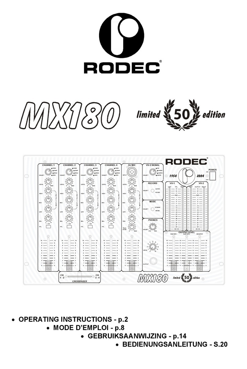
Rodec MX180 MKIII User manual

•OPERATING INSTRUCTIONS - p.2
•MODE D’EMPLOI - p.8
•GEBRUIKSAANWIJZING - p.14
•BEDIENUNGSANLEITUNG - S.20

RODEC MX180 MKIII
2
TABLE OF CONTENTS
- Specifications - 2 -
- Safety instructions - 3 -
- Installation of the mixing panel - 3 -
- Frontpanel, switches and control - 3 -
- Connections - 5 -
- Operating instructions - 6 -
- Subsonic filter - 7 -
- Remote control option - 7 -
- Pictures on cover - 27 -
SPECIFICATIONS
Inputs Input sensitivity Signal/Noise Ratio Remarks
PHONO 1-4
MD/AUX 1-4
CD/DAT 1-4
MIC 1-4 symm.
MIC DJ symm.
assym.
2.3mV/50kΩ
220mV/50kΩ
220mV/50kΩ
4.0mV/4kΩ
0.7mV/1.2kΩ
0.5mV/22kΩ
< -80dB
< -92dB
< -92dB
< -83dB
< -85dB
< -89dB
RIAA correction
Outputs
Master 1 symm.
Master 2 assymm.
Monitor assym.
Recording 1-4
Phones
3.3V/600Ω
1.55V/10kΩ
775mV/10kΩ
500mV/10kΩ
12V/600Ω
Subsonic filter
Subsonic filter
Subsonic filter
Recording out selector
Phones 200-600Ω
- Tone controls: Bass +/-13dB @ 100Hz
Middle +/-13dB @ 1kHz
High +/-13dB @ 10kHz
- Subsonic filter: -25dB @ 10Hz
- Power source: Panels are leaving the factory on: 230V / 50Hz-60Hz
on request: 100V-117V / 50Hz-60Hz
- Fuse: T200mA
- Power consumption: OFF=2.0VA ON=34.5VA
- Approbation: CE-approved
- Dimensions: Front: 482mm x 310mm (19” x 7HE)
Chassis: 444mm x 295mm x 150mm
- Weight: 7.4kg
DESIGN AND SPECIFICATIONS ARE SUBJECT TO CHANGE WITHOUT PRIOR NOTICE.
MODEL MX180MKIII
SERIAL NUMBER …………………………… (on the back of the set)
Please give model and serial number by every information requested.
Thank you very much for purchasing the RODECRODEC mixing panel MX180MKIII.
This mixing panel is a topline mixing panel, capable of outstanding performance in combination with
high grade systems.

RODEC MX180 MKIII
3
SAFETY INSTRUCTIONS
1) Do not expose the set to rain or water. Do not spill liquid or insert (metal) objects inside the
set. Rain, water or liquid such as cosmetics as well as metal, may cause electric shocks,
which can result in fire or shock hazard. If anything gets inside, unplug the power cord.
2) Frayed cords and broken plugs may cause a fire or shock hazard. Do not damage the power
cord. When removing the power cord from wall outlet, be sure to unplug by holding the plug
attachment and not pulling the cord.
3) Do not open the set, there are no serviceable parts inside.
Only qualified service technicians can service inside your set.
4) Operate the set only from a power source which is indicated on the rating label at the back of
the set.
5) Do not use chemical products to clean the set. Do not use contact spray or other products in
the faders. The contact spray can damage the faders.
INSTALLATION OF THE MIXING PANEL
1) The set can be used in every position.
2) Don’t place the set into direct sunlight, or in a warm moist or dusty place.
3) To avoid disturbances, do not place the set in the neighbourhood of disturbing apparatuses.
FRONTPANEL, SWITCHES AND CONTROL
1) Power switch
Controls the supply of AC power to the set. One push turns the mixing panel on, a second
push turns it off. It remains in a stand-by mode.
2) Power "ON" on indicators
These indicators light up when the power is on.
3) VU meters
The two left meters indicate the PFL -or split signal. The right VU-meter displays the output
signals, depending on the position of the VU-2 signal select switch (4).
4) VU-2 signal select switch
With this switch is it possible to select the signal displayed on the two right VU-meters. When
the switch is on the SUM position than will the mix-signal be displayed. On the positions
MASTER 1, MASTER 2 and MONITOR will the according outputsignals be displayed.
5) Mode Switch
This switch is to be used to set the mixing panel in mono or stereo mode. This does not work
on the monitor output
6) Phones output
Output for high level headphone monitoring. With the PFL switches (9) can the connected
audio sources or the output (in split mode) be displayed without manipilating the output signal
(Headphones 200-600Ω).
7) Phones control
This button is used to adjust the volume of the headphones.

RODEC MX180 MKIII
4
8) Left ear signal select switch
With this switch you can listen to the mixed signal in the left loudspeaker of the headphones.
This signal appears then also on the right VU-meter. On the right headphones speaker and
the left PFL VU-meter will the PFL-signal still be displayed.
9) PFL switches
With these switches you can select the different input sources that you will listen to with the
headphones.
10) Input selector
This switch is used to select the input signal: PHONO/AUX/CD/DAT/MD or
MICROPHONE.
11) Level adjuster
These controls are used to adjust input levels of the different inputs.
12) Equalizer controls
This is used to regulate the degree of treble, middle and bass in the sound.
13) Balance-Pan control
The balance between the amount of sound on the left and on the right is adjusted by using
this knob. When it is set to the center position, the gain is the same for the left and the right
channel.
14) Channel faders
Volume control for every input.
15) Remote control switch option
This switch is used to start and/or stop any connected apparatus from the mixing panel.
16) DJ micro input
Microphone input with priority on the input on the back of the set.
17) Level adjuster
Mike level for accurate adjustment of different types of microphones.
18) Equalizer
Triple tone control for DJ microphone.
19) Pan Mic
Panoramic control for the DJ-microphone input. With this button you can place the mike
signal somewhere between left and right.
20) Talk-over control
Variable stage gain control level music suppression.
21) DJ mike fader
Volume control for DJ mike
22) Master output fader
Volume controls final output of mixer towards slave or integrated amplifers.
23) Monitor output fader
Volume control for the signal level for the monitor output, this output does not contain the DJ-
mic signal.
24) Record Select
This switch is used to make recordings with or without the DJ microphone.
+ DJ MIC : in this position you add the signal of the DJ mike to the music.
- DJ MIC : in this position you record only the signal from channel 1 - 4 (8).

RODEC MX180 MKIII
5
This switch has no influence on the master outputs.
25) Crossfader
With this fader you can easily fade over between the channels 1-2 and 3-4. When the knob
stands completely on the left than will the signal of the channels 1 and 2 appear on the
output. When the knob stands completely on the right will the signal of the channels 3 and 4
appear on the output.
CONNECTIONS
A) PHONO input
Phono input with a sensitivity of 2.3mV and build in RIAA correction.
B) Ground
If the recordplayer has a ground wire, connect it to the ground terminal.
C) MD/AUX input
Input with a sensitivity of 220mV. To connect different apparatuses as a tuner, tape
recorder, mini disc, cassette recorder or (HIFI) video recorder.
D) CD/DAT input
Input for compact disc players and digital tape recording.
E) Micro input
Balanced microphone input. To reduce the interference on the microphone cord, you have to
use a microphone with balanced output. The use of a microphone without balanced output is
also possible, in this case please get in contact with your RODEC dealer.
F) Recording outputs
Outputs to connect cassette recorder or (HIFI) video recorders to make recordings. These
outputs can be switched with or without recording the DJ microphone signal. (24)
G) DJ mike input
Balanced microphone input with a sensitivity of 0.7mV.
This input is in combination with the input JACK (16) on the front of the set. The JACK (16)
has priority on the XLR input (G) on the back of the set.
H) Effects IN/OUT
Input and output to connect effect apparatus to the microphone channel. If there is no plug in
the JACK, the microphone channel works normally, if there is a plug inserted in the JACK, the
internal link is interrupted. The sensitivity of this IN/OUT connection is 160mV.
I) Master output 1
Symmetrical output where a power-amplifier can be connected to. The output level can be
manipulated with the master fader 1 (22) from 0 to maximum (3.3V).
J) Master output 2
Assymetrical output where a power-amplifier can be connected to. The output level can be
manipulated with the master fader 1 (22) from 0 to maximum (1.55V).
K) Monitor output
Extra output wherefrom the output voltage can be controlled from 0 to maximum (775mV)
with the monitorfader (23). The musiccompressor, the DJ-micro and the mono/stereo switch
have no influence on this output.
L) Remote control terminal option
The terminal is completely independent of the electronics of this set.
Only for switching low current/low voltage.
Table of contents
Languages:
Other Rodec Music Mixer manuals

Rodec
Rodec miXboX User manual

Rodec
Rodec MX180 MKII User manual

Rodec
Rodec MX180 MKII User manual

Rodec
Rodec MX240 MKIII User manual

Rodec
Rodec MX1400 User manual

Rodec
Rodec MX300 MKIII User manual

Rodec
Rodec MX120 User manual

Rodec
Rodec BX-9 User manual

Rodec
Rodec multi source ii User manual

Rodec
Rodec CX-1100 User manual