Roemheld Hilma HCR-PA-11X10 User manual

HYDRAULIC WORKHOLDING ▪ MACHINE VISES ▪ ZERO POINT MOUNTING
QUICK DIE CHANGE ▪ QUICK MOLD CHANGE ▪ MAGNETIC CLAMPING
PRODUCTS FOR ASSEMBLING
CARR LANE ROEMHELD MFG. CO.
0 | H I L M A
OPERATION AND MAINTENANCE
MANUAL
HCR-PA-11X10 Power Unit

HYDRAULIC WORKHOLDING ▪ MACHINE VISES ▪ ZERO POINT MOUNTING
QUICK DIE CHANGE ▪ QUICK MOLD CHANGE ▪ MAGNETIC CLAMPING
PRODUCTS FOR ASSEMBLING
CARR LANE ROEMHELD MFG. CO.
1 | H I L M A
TABLE OF CONTENTS
1.0 INTRODUCTION PAGE
A. The HCR-PA-11X10 Line of Pumps
B. HCR-PA-11X10 Reservoir Versions
2.0 INSTALLATION AND OPERATION
A. Installation
B. Check List
C. Reservoir Filling and Draining
D. Start-up & Bleeding the System
E. Pressure Switch Setting
F. Kick Down Relief Setting
3.0 MAINTENANCE AND SERVICE
A. General
B. Air Spool Lubrication
C. Trouble Shooting Guide
D. Spare Parts List
4.0 GENERAL ASSEMBLY
A. Mounting the Ratio Plate
B. Mounting the Air Body
C. Mounting the Air Cap
D. Final Assembly
5.0 DRAWINGS

HYDRAULIC WORKHOLDING ▪ MACHINE VISES ▪ ZERO POINT MOUNTING
QUICK DIE CHANGE ▪ QUICK MOLD CHANGE ▪ MAGNETIC CLAMPING
PRODUCTS FOR ASSEMBLING
CARR LANE ROEMHELD MFG. CO.
2 | H I L M A
SECTION 1.0: INTRODUCTION
A. The HCR-PA-11X10 is the latest concept in hydraulic power units. These
Units need no external electrics or plumbing to operate. Just plug in shop air and
the unit is ready to go. The manifold design yields an inherently small package
that can include air and hydraulic gauges, air regulator, exhaust mufflers, and all
necessary pneumatic and hydraulic valves. Thus, the end user enjoys rapid
service and little maintenance.
B. The HCR-PA-11X10 is available with self-contained reservoirs, sized from 20 to
120 cubic inches and including twin internal 40 micron suction filters. These
reservoirs are normally vented like the large tank style but can be furnished with
bellows allowing the pump to be operated at any attitude. Weighing just 15
pounds (30 CI reservoir, filled), the units are ideally suited for portable “all-
attitude” operation.
SECTION 2.0: INSTALLATION AND OPERATION
A. INSTALLATION
1. Self Contained Reservoir version: Drill the four mounting holes on
the intended vertical mounting surface per the dimensions shown
on the enclosed “General Arrangement-Self Contained Reservoir”
Drawing. Mount the pump using four (4) ¼” fasteners.
B. CHECK LIST
Before operating the unit, complete the following checklist to assure proper and
safe operation:
1. All hydraulic components (fittings, hoses, valves, etc.) shall be
rated at, or above the maximum operating pressure of the power
unit.
2. Inlet air pressure must not exceed 150 psig (10 bar). Normal range
of supply air pressure shall be not less than 50 and not over 100
psig (4-7 bar).
3. All air supply fittings and lines shall be of non-corrosive materials
and of pipe size adequate for the pump.
4. Air supply must be free of contaminants and an air filter must be
installed as closely as possible to the pump.

HYDRAULIC WORKHOLDING ▪ MACHINE VISES ▪ ZERO POINT MOUNTING
QUICK DIE CHANGE ▪ QUICK MOLD CHANGE ▪ MAGNETIC CLAMPING
PRODUCTS FOR ASSEMBLING
CARR LANE ROEMHELD MFG. CO.
3 | H I L M A
5. Air lubrication must NOT be used.
6. At initial startup, the air regulator MUST be turned out completely
counterclockwise (CCW) before the supply air source is turned on.
C. RESERVOIR FILLING AND DRAINING
It is recommended that light grade hydraulic oil be used. (ISOVG32) Consult your
distributor or the manufacturer if your application requires other than light
viscosity petroleum based fluids recommended above.
When filling the reservoir, it is important to observe the state of each clamp and
rollblocks if so equipped, to determine their present fluid capacity. All single
acting clamps must be in the unclamped condition, all hydraulic rollblocks must
be in the down (de-energized) condition, all double acting clamps must be in the
fully retracted condition. These conditions must be present before topping off the
oil level in the reservoir. Otherwise additional fluid will be introduced to the
reservoir resulting in overflow.
Remove vent/filler cap. Pour clean oil through a strainer into reservoir until full as
indicated in the upper bulls-eye. Replace vent/filler cap. Top-off the reservoir
after the system has been bled (Sec. D, below).
Note: The self-contained reservoir may be drained in the future via the “B”
cylinder port.
D. START-UP & BLEEDING THE SYSTEM
Once all the above requirements are met and the reservoir is full, make sure the
air regulator is completely turned out counterclockwise (CCW) before connecting
the air supply. Slowly turn in the air regulator clockwise (CW) until the pump just
begins to reciprocate. Alternately extend and retract the cylinder(s), bleeding the
lines at the stroked end of each cylinder.
** Systems that have normally open solenoid valves can manually relieve
pressure to the line by pressing down and holding the “plunger” on top of the
solenoid. After the plunger is released, pressure to the line will build back up.

HYDRAULIC WORKHOLDING ▪ MACHINE VISES ▪ ZERO POINT MOUNTING
QUICK DIE CHANGE ▪ QUICK MOLD CHANGE ▪ MAGNETIC CLAMPING
PRODUCTS FOR ASSEMBLING
CARR LANE ROEMHELD MFG. CO.
4 | H I L M A
E. PRESSURE SWITCH SETTING PROCEDURE
The pressure switch used on the Hilma air power unit is a standard safety feature
for the press. Pressure switches are used to monitor the pressure on system
components, and report these pressure signals back to the press controls,
specifically the emergency stop circuit or E-stop. If pressure is lost then the
press shuts down. Pressure switches are set at 10%-15% below operating
pressure.
Turn the pressure switch adjustment knob counter-clockwise, all the way out.
Now bring the system up to pressure. Using a multimeter on the ohms (Ω)
setting, place the test leads of the voltage meter on terminals 1 and 2 of the
pressure switch. You will have continuity at this point. Turn the pressure switch
screw clockwise until continuity is broken. This process may be repeated for
valve package pressure switches.
**PLEASE NOTE THAT PRESSURE SWITCHES AND RELIEF VALVES ARE PRESET
TO THE CUSTOMER’S SPECIFIC APPLICATION**
Adjustment
Knob
DIN Connector
Pressure Switch
Terminal 2
Terminal 1

HYDRAULIC WORKHOLDING ▪ MACHINE VISES ▪ ZERO POINT MOUNTING
QUICK DIE CHANGE ▪ QUICK MOLD CHANGE ▪ MAGNETIC CLAMPING
PRODUCTS FOR ASSEMBLING
CARR LANE ROEMHELD MFG. CO.
5 | H I L M A
F. KICK DOWN RELIEF SETTING
*** NOTE *** For 'Kick Down Relief Valve' (RV1) only, be sure an orifice disk is
present in the valve cavity faced radius side down before installing a
replacement.
Find the kick down relief labeled (RV1) loosen the lock nut on the adjustment
screw and turn the stem out (CCW) completely. Next turn the stem (CW) one
turn.
Turn the air regulator (CW) slowly until the “kick down” occurs. Make note of the
pressure that the kick down occurs and depressurize the system completely
before any more adjustments are made. Continue to turn the stem (CW) in small
turns. Using the above steps repeat until the correct kick down pressure occurs.
Please note you must depressurize the system in between each set point
change.
SECTION 3.0: MAINTENANCE AND SERVICE
A. GENERAL
1. Upon receipt of the pump, inspect the assembly thoroughly. If physical
damage is evident, do not operate the unit. Consult your distributor or the
manufacturer for replacement parts or corrective action.
2. The HCR-PA-11X10 line of pumps is designed to be virtually maintenance
free as long as the air supply and hydraulic oil are contaminant free.
However, it is recommended that the air cycling valve spool and seals be
greased every six months or annually, depending on usage. To perform
this task, first remove the left side Air Pilot Cap on the left side of the Air
Cap as viewed from the air inlet (Part No. 10298). Extract the Air Spool
(Part No. 10659). Extract the Cages and Tee Seals (Part Nos. 10273 &
10629). Clean all the parts and internal cavity. Apply lithium based,
waterproof grease to each component and reassemble.
Lock Nut
Kick Down
Relief Stem

HYDRAULIC WORKHOLDING ▪ MACHINE VISES ▪ ZERO POINT MOUNTING
QUICK DIE CHANGE ▪ QUICK MOLD CHANGE ▪ MAGNETIC CLAMPING
PRODUCTS FOR ASSEMBLING
CARR LANE ROEMHELD MFG. CO.
6 | H I L M A
B. TROUBLE SHOOTING GUIDE
If a problem arises with the unit, the following guide should help to make an
accurate diagnosis and offer a proper remedy:
SYMPTOM CORRECTIVE ACTION
Pump will not cycle
after extended no-
flow period.
•
Check that supply air pressure exceeds 50 psi.
•Check that Air Cap valve spool is not stuck in mid position; if
so, disconnect and reconnect the air supply to reset the
spool to its default position.
Pump brings
system up to
normal operating
pressure but
"chugs"
intermittently.
•
Check all system components for leaks, including valve or
cylinder that may be bypassing internally.
•If symptom is coupled with evidence of fluid leakage from
the air cap muffler, then internal rod seals are worn
excessively; repair/replace without delay to prevent internal
damage to the pump (Note: This condition is always caused
by contaminated oil).
Pump will not cycle
Pump “short”
cycles
•
Air limit valve in Air Cap failed. Replace.
•Air limit valve in Hydraulic Body failed. Replace.
Pump cycles but
does not generate
pressure.
•
Pump is air bound; check fluid reservoir level and bleed.
•Pump internal check valves are jammed with foreign
material; remove and clean; be sure that reservoir does not
contain any foreign material.
Pump Air Cap
leaking air
continuously.
•
Leak from muffler; spool valve seals worn or contaminated;
clean/replace seals.
•Leak from 4-way air valve cap; stem seals worn or
contaminated; clean/replace cap.
C. RECOMMENDED SPARE PARTS
HCR-PA-11X10-Spare Parts List
Part Number Decription Qty.
HCR-U.10072.SPK SPOOL KIT FOR P 100/20 1
HCR-HH-10017 2-WAY AIR VALVE ASSY 2
HCR-U.P100.DSK DYNAMIC SEAL KIT FOR P 100/20 1
HCR-HH-P-SSK STATIC SEAL KIT FOR P 100/20 1
HCR-HH-10016 AIR REGULATOR KIT FOR P 100/20 1

HYDRAULIC WORKHOLDING ▪ MACHINE VISES ▪ ZERO POINT MOUNTING
QUICK DIE CHANGE ▪ QUICK MOLD CHANGE ▪ MAGNETIC CLAMPING
PRODUCTS FOR ASSEMBLING
CARR LANE ROEMHELD MFG. CO.
7 | H I L M A
SECTION 4.0: GENERAL ASSEMBLY
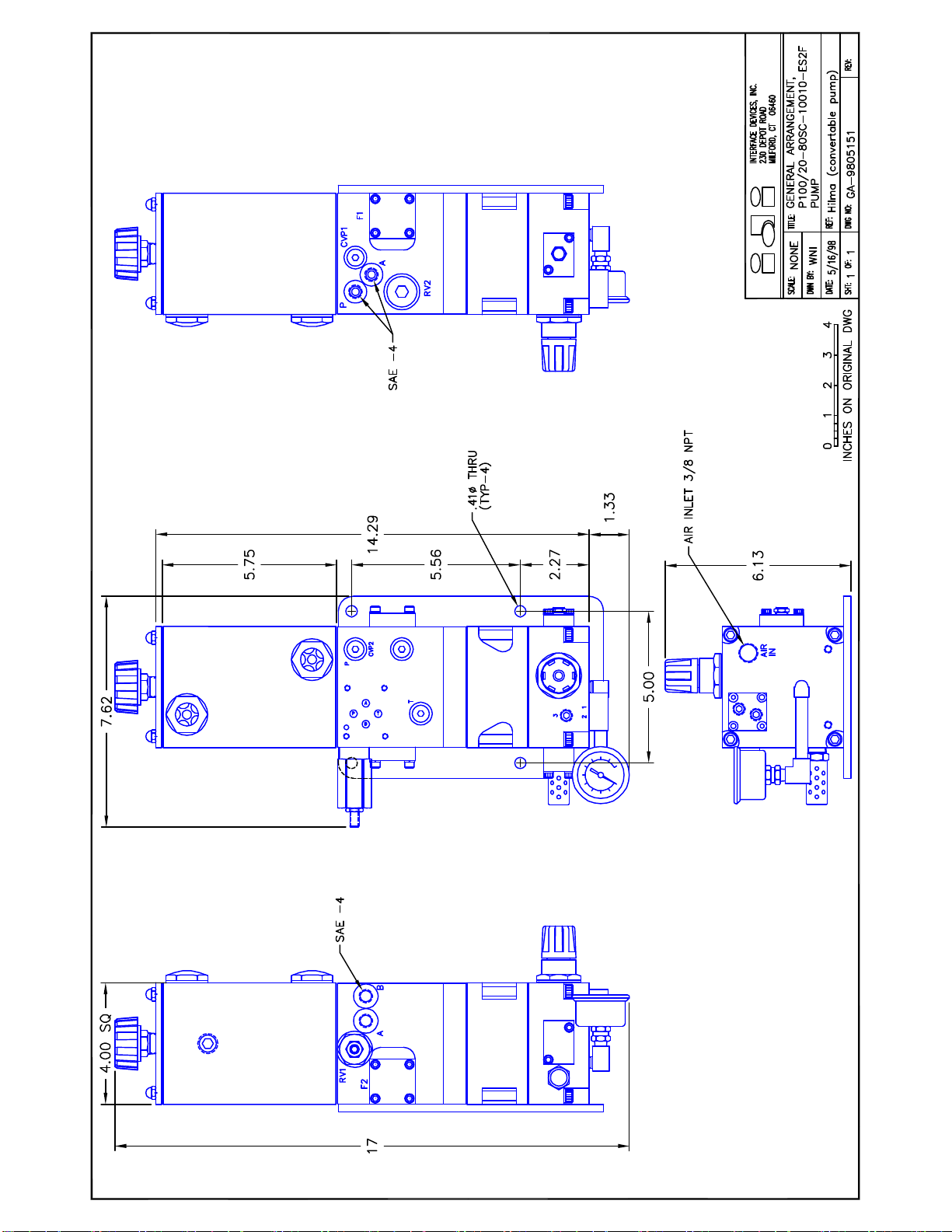
This section is provided to a general overview for all the service needs of the HCR-PA-
11X10 line of pumps. An exploded view with Bill of Materials of all parts is included at
the back of this manual.
The general assembly of the HCR-PA-11X10 line of pumps consists of three major sub-
assemblies: AIR CAP, AIR BODY, and HYDRAULIC BODY. It is most efficient if each of
these three components is entirely sub-assembled prior to final assembly.
A. MOUNTING THE RATIO PLATE TO THE HYDRAULIC BODY
Make sure that all components are clean and dry. Spread a thin film of
waterproof grease on the rod, hydraulic piston and bore. Place static seals (O-
rings) in the appropriate counterbores in the Hydraulic Body.
While holding the Ratio Plate sub-assembly by the air-end piston, align the
actuator to its counterbore and gently rock the hydraulic piston into the bore.
Slide the Ratio plate down the shaft until contact is made with the Body. Next,
install the four mounting bolts (1/4-20 x 1”) and lock-washers into the center
pattern and snug to just compress the lockwashers. If there are two more bolt
holes along the bottom edge, install these bolts now, without lock-washers, and
snug.
Lastly, tighten all bolts in small increments using a cross-type pattern to a final
torque of approx. 15 ft/lb.
B. MOUNTING THE AIR BODY TO THE RATIO PLATE
Slip one air body gasket over the air piston and align to the edges with the
hydraulic body. Apply a thin film of waterproof grease to the bore of the Air Body
and lay atop the piston with chamfered bore edge down. Holding the Air Body
and piston with both hands, “squeeze” the body over the air piston seal and
wiggle down until contact is made with the body gasket.
Make sure that the serialized face of the Air Body is facing up. On later models,
body pins assure proper alignment. At this point, tie down the Air Body through
the Ratio Plate to the Hydraulic Body with the four mounting bolts (5/16-18 x 1
¾'') and lock washers. Snug the bolts until the lock-washers are compressed,
NOT torqued.

HYDRAULIC WORKHOLDING ▪ MACHINE VISES ▪ ZERO POINT MOUNTING
QUICK DIE CHANGE ▪ QUICK MOLD CHANGE ▪ MAGNETIC CLAMPING
PRODUCTS FOR ASSEMBLING
CARR LANE ROEMHELD MFG. CO.
8 | H I L M A
C. MOUNTING THE AIR CAP TO THE AIR BODY
Be sure the Air Cap is fully sub-assembled before mounting it to the Air Body.
Place another air body gasket on the Air Body and align to the edges. Place the
Air Cap on the Air Body with the Air Regulator adjusting knob in plane with the
DO-3 pad on the hydraulic body.
D. FINAL ASSEMBLY
Align the bottom faces of and tie down the Air Cap through the Air Body and
Ratio Plate to the Hydraulic Body using the four mounting bolts (5/16-18 x 4 ½'')
and lock-washers. Snug the bolts using a cross pattern.
Connect a temporary air supply to the pump (NO OIL YET) and be sure the air
regulator is turned out fully (CCW). Slowly turn in (CW) the air regulator until the
pump barely reciprocates. Then, while running, torque all eight Air Body bolts to
approx. 20 ft/lb. using a cross pattern. If the pump stalls or binds during torquing,
remove all air pressure, loosen all eight bolts and restart the procedure.


Table of contents
Popular Portable Generator manuals by other brands

Agilent Technologies
Agilent Technologies E4438C manual

Woodward
Woodward EGCP-1 Operation and Users Manual

Yamaha
Yamaha EF4500iSE - Inverter Generator owner's manual

Nature's Generator
Nature's Generator Elite user manual

Champion Global Power Equipment
Champion Global Power Equipment 100396 Operator's manual

DUROMAX
DUROMAX DUAL FUEL XP4500IH user manual