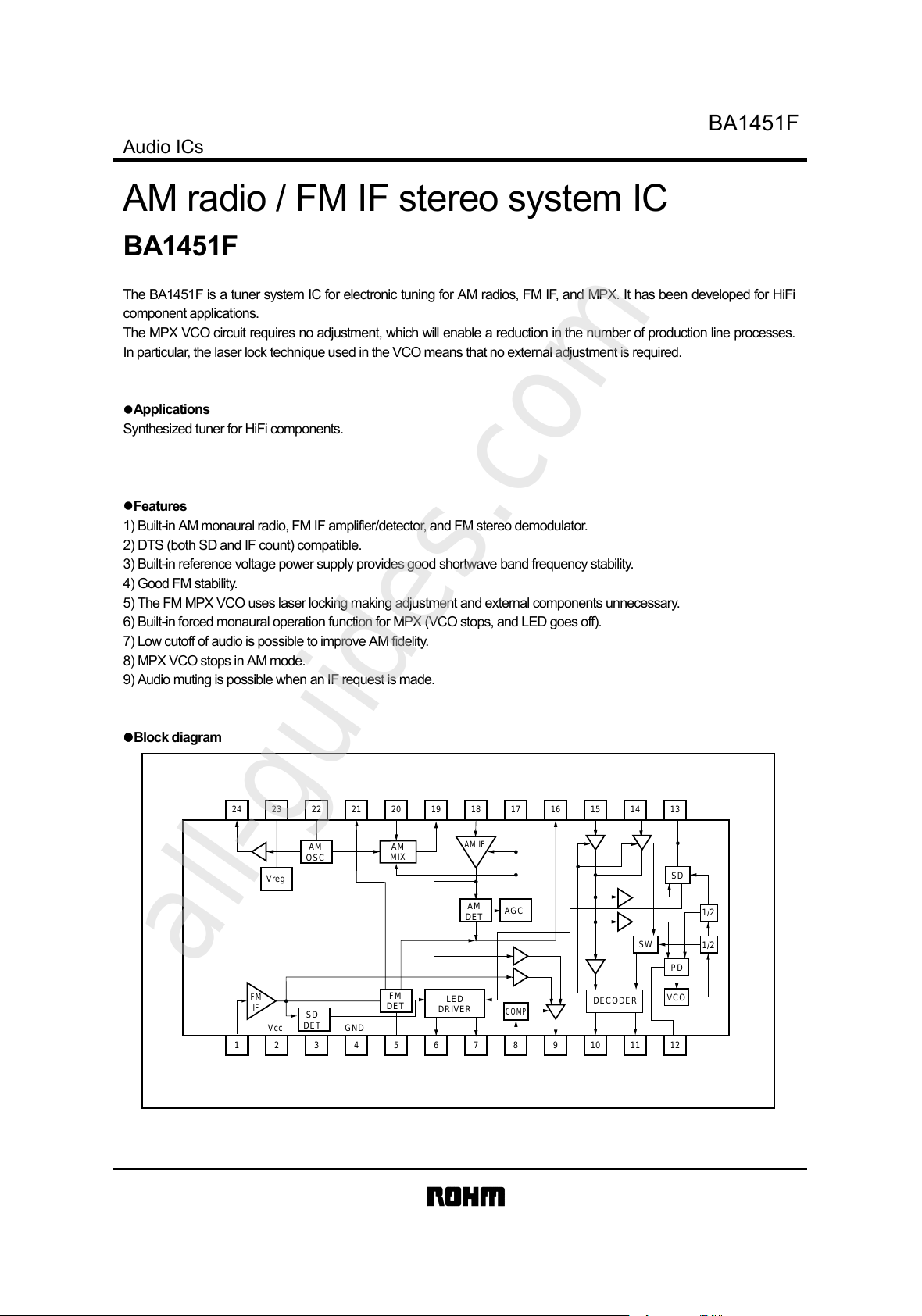
BA1451F
Audio ICs
FM AM
21 2.1 2.1
23 2.1 2.1
22 2.1 2.1
24 1.7 1.4
21
2
4
4.3kΩ
V
CC
GND
22
24
23
4
100Ω
V
reg
GND
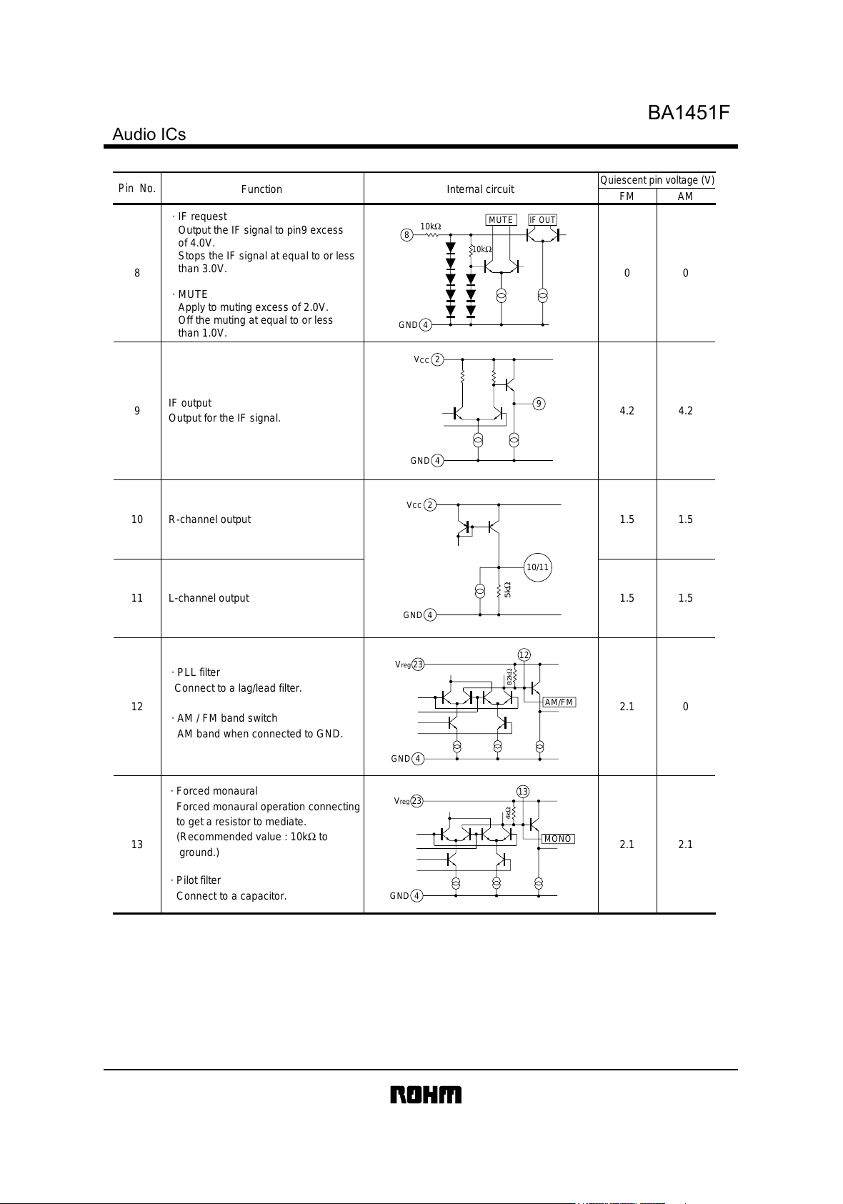
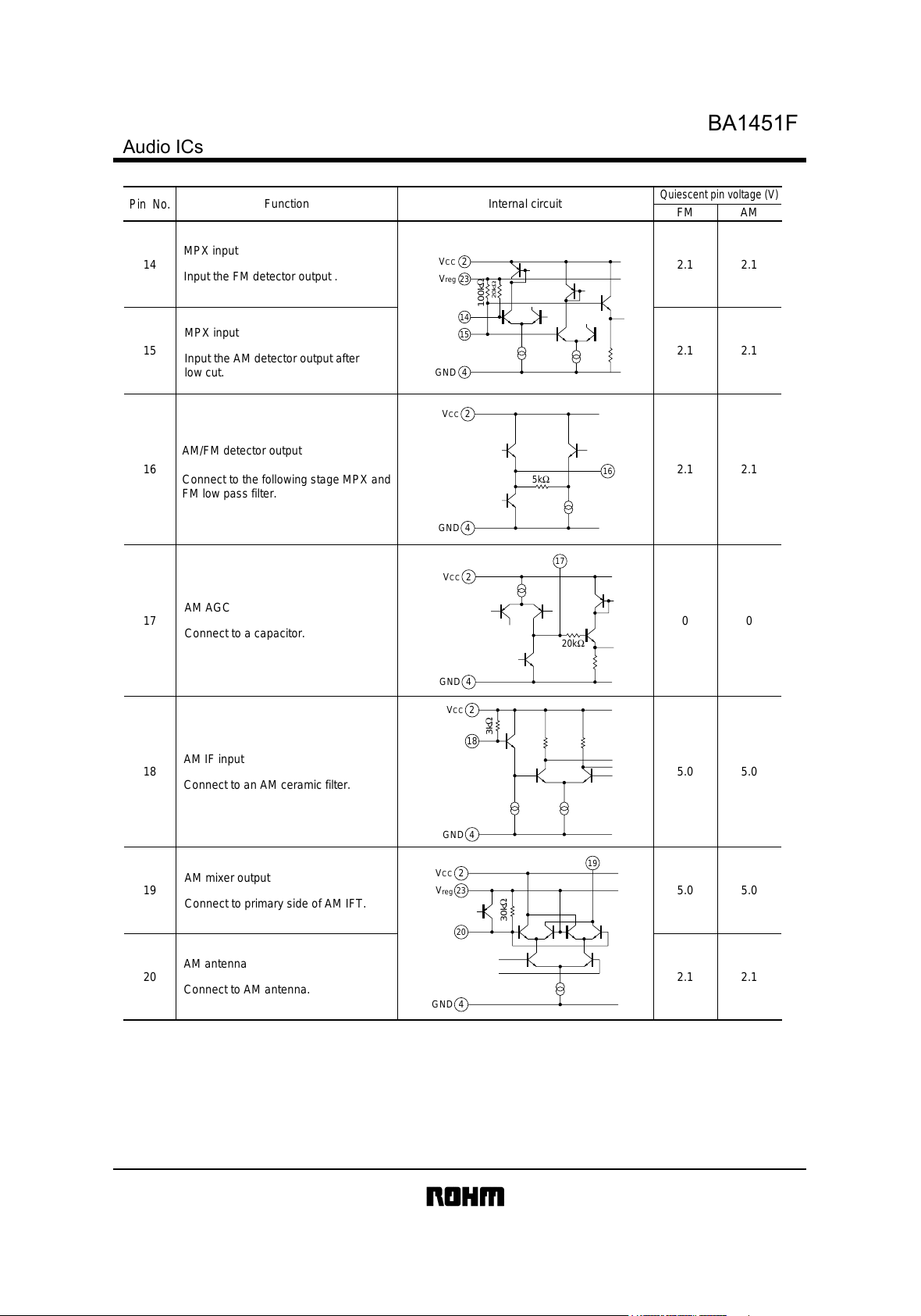
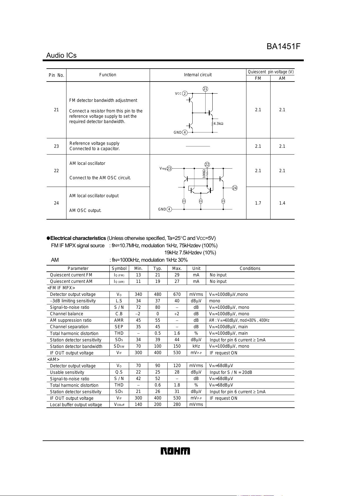
Pin No.
Function Internal circuit
Quiescent pin voltage (V)
FM detector bandwidth adjustment
Connect a resistor from this pin to the
reference voltage supply to set the
required detector bandwidth.
Reference voltage supply
Connected to a capacitor.
AM local oscillator
Connect to the AM OSC circuit.
AM local oscillator output
AM OSC output.
!
!!
!Electrical characteristics (Unless otherwise specified, Ta=25°C and VCC=5V)
FM IF MPX signal source : fiN=10.7MHz, modulation 1kHz, 75kHzdev (100%)
19kHz7.5kHzdev(10%)
AM : fiN=1000kHz, modulation 1kHz 30%
Parameter Symbol Min. Typ. Max. Unit Conditions
I
Q (FM)
29 mA
I
Q (AM)
11 19 mA
V
O
mVrms V
IN
=100dBµV,mono
L.S 40 dBµV mono
S / N −dB V
IN
=100dBµV, mono
C.B −20+2dBV
IN
=100dBµV, mono
AMR −dB
AM : VIN
=
60dBµV, mod
=
30% , 400Hz
SEP 35 45 −dB V
IN
=100dBµV, main
THD −%V
IN
=100dBµV, main
SD
S
dBµV
SD
SW
100 V
IN
=100dBµV, mono
V
IF
300 400 530
V
O
90 120 mVrms V
IN
=68dBµV
Q.S dBµV
S / N 42 52 −dB V
IN
=68dBµV
THD −0.6 1.8 % V
IN
=68dBµV
SD
S
dBµV
V
IF
300 400 530
V
OBuff
140 200 280 mVrms
mV
P-P
mV
P-P
kHz
13 21
340 480 670
27
34 37
72 80
45 55
0.5 1.6
34 39 44
70 150
70
22 25 28
21 26 31
Quiescent current FM
Quiescent current AM
<FM IF MPX>
Detector output voltage
−3dB limiting sensitivity
Signal-to-noise ratio
Channel balance
AM suppression ratio
Channel separation
Total harmonic distortion
Station detector sensitivity
Station detector bandwidth
IF OUT output voltage
<AM>
Detector output voltage
Usable sensitivity
Signal-to-noise ratio
Total harmonic distortion
Station detector sensitivity
IF OUT output voltage
Local buffer output voltage
No input
No input
Input for pin 6 current ≥1mA
IF request ON
Input for S / N = 20dB
Input for pin 6 current ≥1mA
IF request ON