Ten-Tec 238c User manual

Ten-Tec 238C manual
Part #74428
First release, June 2009. Printed in U.S.A.
CHAPTER 1
MODEL 238C INSTALLATION
Model 238C is a high power antenna tuner
that uses an adjustable reactive network for
matching the unbalanced 50 ohm output
impedance of transmitters and transceivers
to a variety of balanced and unbalanced
loads. It is usable over a frequency range of
1.8 to 30 MHz. Provision is made for
selecting one of four antennas or for by-
passing the matching network. A cross-
needle SWR and wattmeter with switchable
200 and 2000 watt scales and selectable
peak and average power output reading is
included.
UNPACKING YOUR NEW TUNER
Examine your model 238C for signs of
shipping damage. Should any damage be
apparent, notify the delivering carrier
immediately, stating the full extent of the
damage.
Retain all damaged cartons if damage is
apparent. Liability for shipping damage
rests with the carrier. We also recommend
that you keep the carton and packing fillers
in the event that storage, moving, or
shipment becomes necessary.
The following hardware and accessories are
packed with your 238C. Make sure that you
have not overlooked anything.
(1) #23160 Capacitor, 1000 pF, 1 kV
(1) #38088 .062” hex Allen wrench
(1) #74020 Warranty card
(1) #74428 238C Operator’s Manual
TRANSMITTER CONNECTION
The model 238C is designed for connection
to transmitters having a 50 ohm nominal
output impedance. Connect the coaxial
output of your transmitter to the SO-239 type
INPUT connector on the rear panel of the
tuner with a 50 ohm coaxial cable.
GROUND CONNECTION
Connect your station ground system to the
GND wing nut terminal on the rear panel of
the tuner with heavy braid or wire. The
ground connection should go directly to the
earth ground system using as short a lead
as possible.
ANTENNA CONNECTIONS
Connect antenna transmission line(s) to the
appropriate terminal(s) on the tuner as
follows.
For 50 ohm coax-fed antennas (unbalanced
transmission lines) use ANT 1, ANT 2, ANT
3 or ANT 4.
For a single wire antenna connect to
SINGLE WIRE terminal. The SINGLE WIRE
terminal uses the ANT 4 antenna
connection.
For balanced feedline systems, adding a
jumper from SINGLE WIRE to one of the
BALANCED LINE terminals as shown on the
rear panel is required. A tin-plated steel
jumper for this purpose has been provided.
It is attached to one wing nut connector on
the back; if balanced line will be used, attach
the other side of the jumper to the other
wing nut. Then connect the feedline to the
two BALANCED LINE terminals.
ANT position 4 can be coax, single wire, or
balanced line. ANT 1, ANT 2, ANT 3 must
be coax only.
In both single wire and balanced line
systems, take special care to route the
transmission line as far away from the
station equipment as possible. Never drape
lines over the transmitter. These lines have
high voltage points inside the shack which
can produce strong RF fields.
Please note that 238C does NOT allow for
the connection of either coax-fed and
balanced line or single wire antennas to the
ANT 4 connection at the same time. There
is no switchable configuration for ANT 4 –
any antennas connected to these jacks will
be in use. If you have a coax fed antenna
and a balanced line or single wire antenna
connected to ANT 4 at the same time, both
of these antennas will be in use when ANT 4
is selected from the front panel.

Ten-Tec 238C manual
Part #74428
First release, June 2009. Printed in U.S.A.
DC POWER CONNECTION
The 238C dual cross-needle wattmeter
requires 12-15 VDC (13.5 VDC nominal) for
meter lamp illumination and to power the
peak-reading power output circuitry.
Connect a cable from your 12-15 VDC
power source to the rear panel 13.5 VDC
jack. Center tip is positive, shell/case is
negative. It is only necessary to connect DC
power to operate the peak-reading
wattmeter function and to illuminate the
meter lamp. SWR metering and the
average reading power output metering are
usable even with no DC power connected.

Ten-Tec 238C manual
Part #74428
First release, June 2009. Printed in U.S.A.
Figure 1-1 238C Front and Rear Panel

Ten-Tec 238C manual
Part #74428
First release, June 2009. Printed in U.S.A.
CHAPTER 2
OPERATING INSTRUCTIONS
The following set of instructions will allow
the operator to quickly place the 238C into
operation. Included are descriptions of the
front panel controls and their functions. This
is followed by instructions for antenna
matching and selection, and a brief
discourse on antenna systems matching
theory. Figure 1-1 on the previous page
shows a visual representation of each item
on model 238C and its function or use.
FRONT PANEL CONTROLS
(1) CAPACITOR
This control connects to the variable tuning
capacitor used as one of the elements in the
“L” type matching network. This capacitor
has a tuning range of 40-500 pF and is
continuous tuning with no stops. A marker
system of digits from 0-10 is silk screened in
a 180 degree arc around the top of this
control to make returning to earlier settings
easier and quicker.
(2) INDUCTOR
This control is connected to the roller
inductor, another element in the “L” type
matching network. This inductor has a
tuning range of 0.2-18 uH which is covered
in approximately 30 revolutions of the
control knob. A gear reduction system
behind the front panel of the 238C is
connected to a concentric skirt turns counter
numbered 0-30 in a 180 degree arc over the
top of this control, to make returning to
earlier settings easier and quicker.
(3) IMPEDANCE SWITCH
This 11 position rotary switch is used to
change the configuration of tuning network
for matching either high or low impedance
antenna systems. This switch also selects
additional capacitors as needed for
matching at lower frequencies. When
placed in the 12 o’clock position, the tuner is
connected to the BYPASS configuration and
the network has no effect on the
transmission line systems (antennas are fed
through directly from the transmitter to the
antenna without use of the tuner). The
SWR and power metering remains usable
even when this switch is set to BYPASS.
The purpose of this switch is to set the
capacitor either across the input or across
the antenna, depending on whether a load
of above or below 50 ohms is trying to be
matched (reverses the “L” network).
(4) ANTENNA SELECT KNOB
This 4 position switch is used to select one
of up to four antennas connected to the rear
panel of the 238C and correspond to the
ANT 1, ANT 2, ANT 3, and ANT 4
connectors.
(5) METER
The meter on model 238C is a dual cross-
needle SWR and average or peak-reading
wattmeter. Forward power output is
measured on the right-hand needle, left-
hand scale. Reflected power is read on the
left-hand needle, right-hand scale. SWR is
read by reading the point at which the two
needles cross, on the red scale lines on the
face of the meter. Power output is read in
switchable scales of 200 or 2000 watts.
Peak-reading wattmeter function requires
that 12-15 VDC be connected to the 13.5
VDC rear panel jack. Average power and
SWR can be read even without DC power
connected.
(6) PEAK/AVERAGE SWITCH
This switch is used to select either average
or peak power output reading power on the
238C meter. DC power must be connected
to the rear of the tuner to enable the peak
reading function. Average power can be
read with or without DC power connected.
(7) POWER SCALE SWITCH
The power scale switch is used to set the
power output metering to scales of either
200 or 2000 watts.

Ten-Tec 238C manual
Part #74428
First release, June 2009. Printed in U.S.A.
REAR PANEL CONTROLS
(8) MAIN ANTENNA CONNECTORS
Four SO-239 type connectors labeled ANT
1, ANT 2, ANT 3, and ANT 4 are provided
for the connection of 50 ohm coaxial
antennas.
(9) WING NUT ANTENNA CONNECTORS
Wing nut antenna connectors are provided
on the ANT 4 connection for connection of
either a single wire or balanced line-fed
antenna. Please note a jumper must be
installed between the SINGLE WIRE
terminal and one of the BALANCED LINE
terminals before balanced line is used.
A tin-plated steel jumper for this purpose
has been provided. It is attached to one
wing nut connector on the back; if balanced
line will be used, attach the other side of the
jumper to the other wing nut. Then connect
the feedline to the two BALANCED LINE
terminals.
Please note that 238C does NOT allow for
the connection of either coax-fed and
balanced line or single wire antennas to the
ANT 4 connection at the same time. There
is no switchable configuration for ANT 4 –
any antennas connected to these jacks will
be in use. If you have a coax fed antenna
and a balanced line or single wire antenna
connected to ANT 4 at the same time, both
of these antennas will be in use when ANT 4
is selected from the front panel.
(10) EXTERNAL CAPACTIOR
Some low impedances on 160 meters may
require more capacitance than the 2400 pF
available with the variable tuning capacitor.
Extra capacitance can be added if needed.
See the instruction titled 160 METER
OPERATION NOTE elsewhere in this
chapter.
(11) INPUT
A 50 ohm coaxial cable is to be connected
from the output of your transceiver or linear
amplifier to this jack.
(12) 13.5 VDC
The 238C dual cross-needle wattmeter
requires 12-15 VDC (13.5 VDC nominal) for
meter lamp illumination and to power the
peak-reading power output circuitry.
Connect a cable from your 12-15 VDC
power source to the rear panel 13.5 VDC
jack. Center tip is positive, shell/case is
negative. It is only necessary to connect DC
power to operate the peak-reading
wattmeter function and to illuminate the
meter lamp. SWR metering and the
average reading power output metering are
usable even with no DC power connected.
(13) GROUND
Connect your station ground system to the
GND wing nut terminal on the rear panel of
the tuner with heavy braid or wire. The
ground connection should go directly to the
earth ground system using as short a lead
as possible.
ANTENNA MATCHING
The procedure shown below will enable you
to match almost any antenna system.
Please note that this does not mean 238C
will match any antenna system you may
employ on any given HF frequency. The
238C’s matching range is at least 10:1 SWR
at full rated power output of up to 2000
watts. Some odd length center-fed wire
antennas can easily have a transmission
line impedance in the thousands of ohms;
these antennas cannot be matched by the
238C or any other antenna tuner.
EASY START GUIDE
Read all the information in the manual
leading up to this point, then use the below
instructions to start using your tuner.
Set CAPACITOR to “2” and INDUCTOR to
fully counter-clockwise (“0”) and the center
switch to BYPASS.
Turn the center switch to the LOW Z 1
position (immediately to the left of BYPASS).
Apply 30 to 50 watts of transmitter power
and note SWR shown on the meter. Unkey
the transmitter, and then move the switch to
the HIGH Z 1 position. Apply 30 to 50 watts

Ten-Tec 238C manual
Part #74428
First release, June 2009. Printed in U.S.A.
or less of transmitter power and note SWR
shown on the meter. Depending on which of
the HIGH Z 1 or LOW Z 1 settings showed a
lower SWR, try more positions on the same
side to see if the SWR is lower. Choose the
position among all switch positions that
shows lowest SWR.
Adjust the capacitor for lowest SWR. Then
turn the roller inductor clockwise to a higher
setting and note if SWR changes. If SWR
drops, adjust the capacitor for a lower SWR
value. Go back and forth between these two
controls, adjusting them for best match and
the lowest available SWR.
If the capacitor shows best meter null
(lowest SWR) at a setting of ‘0’, turn the
center switch to the other side of BYPASS.
If the best meter null (lowest SWR) is with
the capacitor at ‘10’, turn the center switch
to the next higher position.
It is possible depending on your antenna
and the frequency in use that a good
‘starting’ match may not be readily apparent
(i.e. all starting positions on the center
switch show a somewhat high SWR). Try
adjusting the roller inductor and/or capacitor
to a higher initial setting and repeat the
same instructions if this is the case.
WARNING: While all the components of the
238C are rated to easily handle continuous
duty operation at full rated power, do NOT
adjust the antenna tuner when running high
output power. Adjust the tuner for lowest
SWR at less that 50 watts, and then enable
your linear amplifier. High circulating
currents are present when high power is
applied to the tuner; adjusting the tuner
controls for lower SWR while running high
power through the tuner can damage the
unit.
WARNING: In normal operation, the 238C
produces very high RF voltages and
currents. We do not recommend operation
of this tuner without the top cover securely
installed due to the danger of contact with
high voltage.
WARNING: Always be sure that a dummy
load or antenna is properly connected when
power is applied. Voltages in excess of
ratings can occur if no load is connected.
BALANCED LINE OPERATION NOTE
When using balanced line, if the SWR rises
during a long transmission it is an indication
that a significant portion of the transmitter
power is being lost in the balun. This will be
the case when the antenna impedance is
greater than 500 ohms. Changing the
length of the antenna and/or feedline will
usually cure this problem. Also be aware
(as noted elsewhere in this manual and on
the rear panel of the 238C) that a jumper
must be connected between one of the
balanced line terminals and the SINGLE
WIRE terminal on the rear of the 238C
before balanced line is used. A jumper
attached to one wing nut connector on the
rear panel has been provided for this
application.
160 METER OPERATION NOTE
Some low impedance antenna loads on 160
meters may require more capacitance than
the 2400 pF available with the variable
tuning capacitor at full mesh and the center
switch at position 5 on the LOW Z side
(example: tuning a shortened whip antenna
on 160). If such a condition exists, adding
additional capacitance across the variable
capacitor will usually produce a better
match. A low loss ceramic or mica
transmitting capacitor should be used.
A ceramic capacitor, Ten-Tec part #23160,
1000 pF, 1 kV, is included in the model
238C packing kit for your use. If needed,
install the capacitor by connecting it
between the two EXTERNAL CAPACITOR
wing nuts located vertically on the rear
panel. Most antenna installations will have
no need to install this capacitor.
ANTENNA SYSTEMS MATCHING
THEORY
Most transmitters are designed to work into
a 50 ohm resistive load, and they are not
able to effectively supply RF power to loads
that depart far from this value. However,
many antenna systems, which include the
antenna and the transmission line have
complex impedances that make it difficult, if
not impossible, to load the transmitter
properly. These impedances are a function
of the operating frequency, type of antenna,

Ten-Tec 238C manual
Part #74428
First release, June 2009. Printed in U.S.A.
type and length of transmission line, height
of antenna and its proximity to other objects.
The model 238C provides a coupling
method to convert the resistive/reactive load
to a pure resistance of 50 ohms that will
accept maximum power from the transmitter.
This is not to say that any and all antennas,
when converted to a 50 ohm resistive
impedance by means of a tuner will give
identical performance. To best understand
the tuner adjustments required, it is
necessary to have a fundamental knowledge
of how antenna systems function. It is
recommended that additional reading on the
subject be done by those interested in
obtaining maximum performance from their
antenna systems. The ARRL Antenna
Handbook, ARRL Radio Amateur’s
Handbook (antenna and transmission line
sections), Low Band DXing by John
Devoldere, ON4UN and other antenna
books published by the publishers of
amateur radio magazines are excellent
sources for information.

Ten-Tec 238C manual
Part #74428
First release, June 2009. Printed in U.S.A.
CHAPTER 3
SPECIFICATIONS
Circuit Type: L network
RF Power Rating: 2000 watts
Frequency Range: 1.8-30 MHz continuous
Input Impedance: 50 ohms nominal
Output Matching Range: At least 10:1
SWR, any phase angle.
Input/Output Connectors: Input and four
antenna coax connectors are SO-239, UHF
type. Studs with wing nuts for single wire
and balanced feeders.
Capacitor Voltage Rating: 3500 volts
Inductor: 0.2-18 uH silver-plated roller
inductor.
Size: 5” H x 12.125” W x 13.5” D
(12.7 x 30.8 x 34.3 cm). Depth
measurement cabinet only, does not
account for knobs or connectors.
Weight: 12 lbs (5.45 kg).
TECHNICAL INFORMATION
The matching circuit used in the model 238C
is basically an “L” network. The “L” network
has several advantages over other circuit
configurations. It has only two adjustable
parts; one inductor and one capacitor; most
other networks use three. Because there
are no internal nodes in the network, the
maximum circuit voltages and currents
which occur are never more than those
present at the input or output terminals.
Because there are only two variable
components, there is only one setting of
each which will provide a perfect match to a
given load impedance, and this unique
setting automatically provides the lowest
network Q possible. Low Q means low
circulating currents, hence low loss, and it
also provides the widest frequency
bandwidth of operation before retuning is
necessary. Finally, since the inductor is
always series, the network always provides
a two-pole low pass response to provide
harmonic rejection.
There are, however, some disadvantages
which have prevented wider use of the “L”
network in the past. First, to match all
possible antenna loads, two configurations
are required. One, for impedances greater
than 50 ohms (i.e. the antenna has a fairly
low SWR already) the values of L and C in
the network required for a perfect match
become very small, smaller than the stray or
minimum values of the components used.
To circumvent this problem, a small fixed
compensating capacitor or inductor is placed
into the circuit depending upon whether the
network is configured for low or high
impedance respectively (HI Z or LO Z on the
center tuner switch). At low frequencies, the
value of network capacity needed to match
some loads is quite large, requiring a large
and expensive capacitor. To provide for
this, fixed capacitors are placed in parallel
with the variable capacitor to obtain the
value needed. This function is performed by
the center switch; further rotation from the
center position increases the value of
capacitance in the circuit.
There are 5 tuner configurations that are
possible depending on the position of the
center switch.

Ten-Tec 238C manual
Part #74428
First release, June 2009. Printed in U.S.A.
METER CALIBRATION
A metal plate is installed on the front of the
238C with 4 Philips screws. This plate has
the markings for the capacitor, inductor and
center impedance switch. It can be
removed without taking off either of the two
main knobs or the center switch knob.
Disconnect the tuner from DC power
connected to the rear panel 13.5 VDC jack.
Remove the 4 screws that hold the metal
plate in place and the metal plate itself.
Behind the metal plate are two plastic
screws for each meter movement. Adjust
each as needed to reset the indication to ‘0’.
Re-install metal plate and reconnect DC
power.

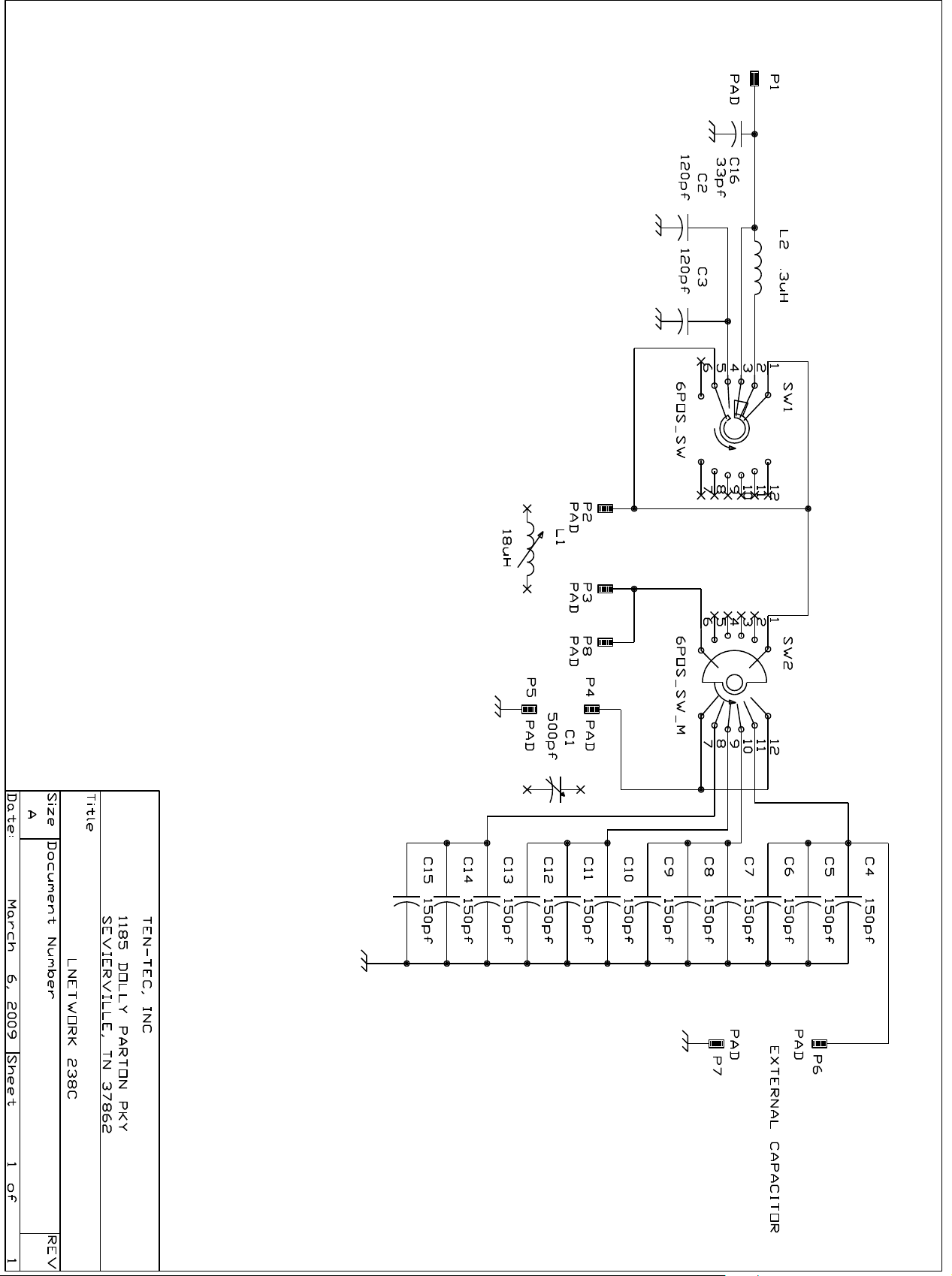
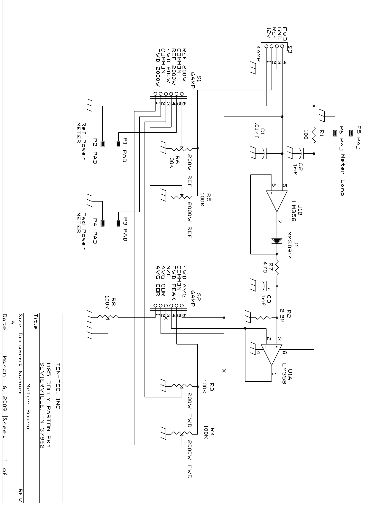

Table of contents
Other Ten-Tec Tuner manuals


