CONTENTS
FUnCUONAal
BIOCK
DIAGlaM:
¢ssicvadeesiccenntatiosecueeiieteddesasctacsaseteaeniaies
Seas
2
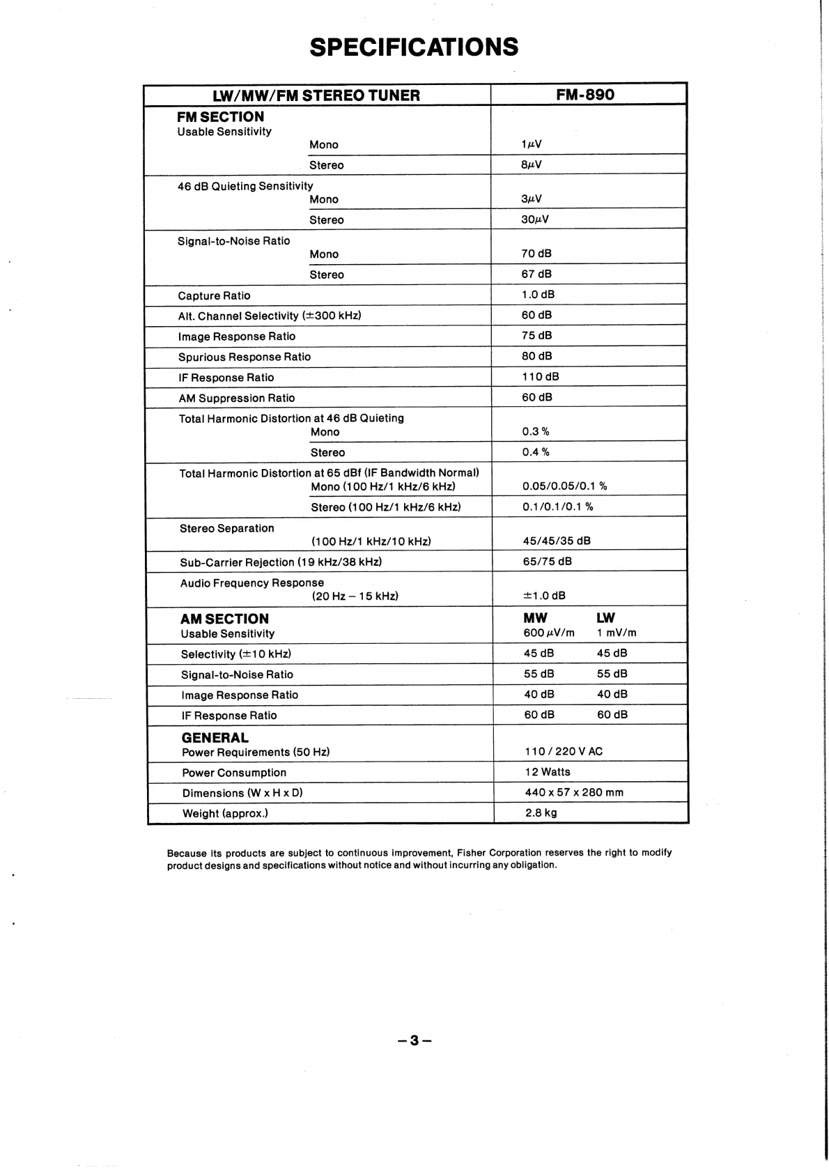
SDSCHICALIONS
42
hctreese
caret
pusen
teresa
epee
tian
ndees
nepeeimenaandeouscuswssansea
bess
3
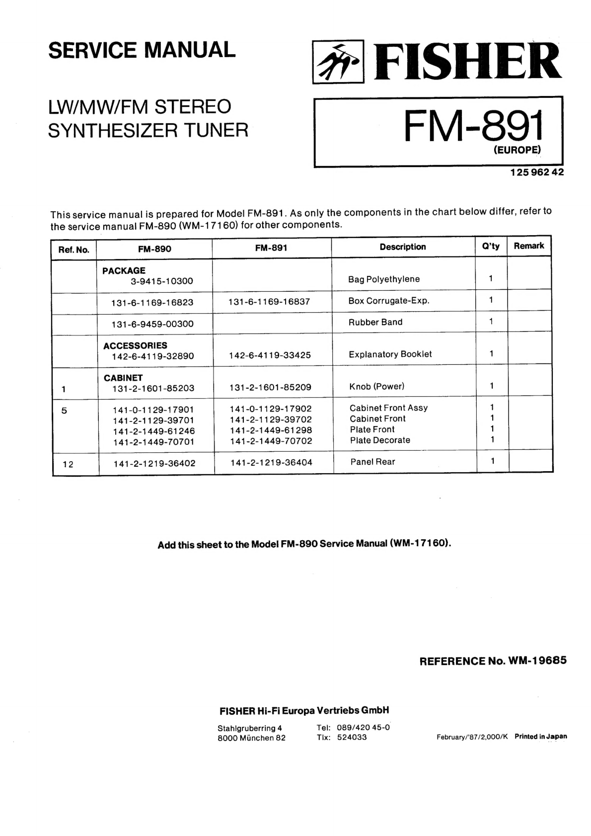
Cabinet
&
Chassis
Exploded
View
........
ccc
ccc
ccc
cece cece
e
eter
eet
een
eeeeeneeenenaes
4
Cabinet
&-Chassis
Pats
LiSt
scocicsncrk
dca
bennce
Chamtiandsuetaieeaeueiseosareew
ieee
5
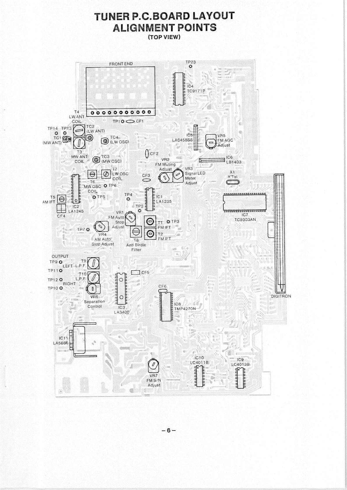
Tuner
P.C.Board
Layout
Alignment
Points
(Top
View)
................c
cece
cence
eens
6
AM
FUNC
AUQNMONt
asi
tucconteliceadietieseon
ides
deena
see
el
or
ecar
epsdanaacitweeagues
7
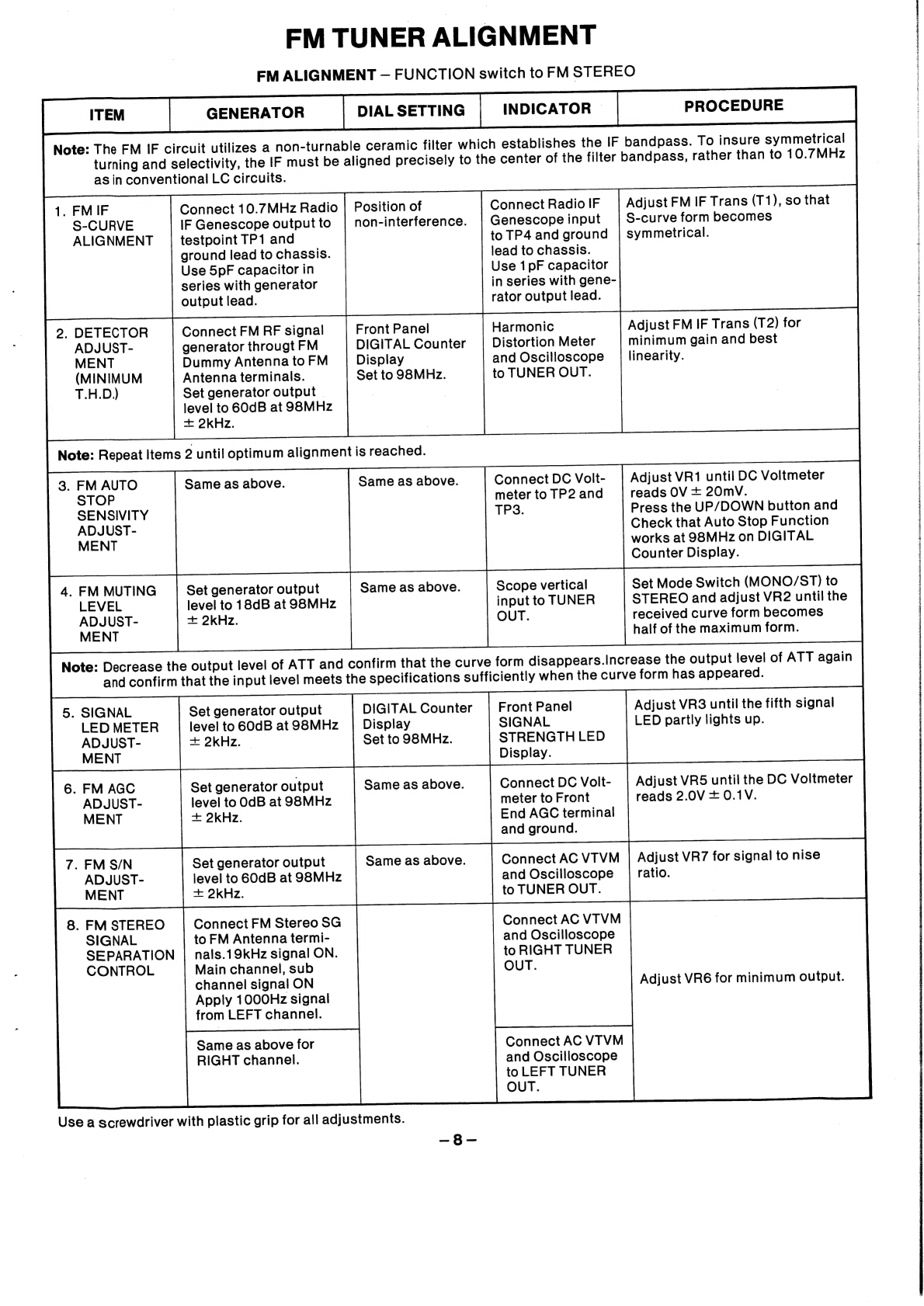
HEM
TUNer
AlIQAMONt
otteissnnscuasesdetsacnvedacawertuehs
Goudocansiaeadesmmnciuniananks
8
IC
Equivalent
Circuit
&
Block
Diagram
...............c.
cece
eee
ees
eee
9,10,11,12,13
P.C.Board
Parts
List
......
be
eich
casas
astec
evens
Seep
anis
nee
emasaesoecee
Tue
oae
14,15,16,17,18
Preset
Switch
P.C.Board
(Bottom
VieW)
...........:ecceceecneeneeee
teen
eeeeeeeenenes
19
‘Antenna
P.C.Board
(Bottom
View)
..........c.ccccseceeceeeeeeeeeeeeeeeeeeeeneeaeeneaees
19
Remote
Control
Input
P.C.Board
(Bottom
View)
..............ccecceeceeeseeteeneeeeeees
19
Band
Switch
P.C.Board
(Bottom
VieW)
...........00cceecceecccecceeececevaceeeeneeeennes
20
Meter
LED
P.C.Board
(Bottom
View)
.............seeecee
eee
eeee
ee
te
eee
e
eee
e
teen
nena:
20
Power
Switch
P.C.Board
(Bottom
View)
............ccecccceeeeseeee
eens
Sg
ae
eae
20
Schematic:
Diagram
orcacsuasncrcaun.ns
acs
uncadave
rues
Sande
weveea
aoe
ae
ieee:
21,22
Tuner
Printed
Circuit
Board
(Bottom
View)
............0cccceecceceeeeeeeeeeueeaeees
23,24
Front
End
Schematic
Diagram
..............0ceceeneee
eee
ee
eee
tent
eee
se
ee
ea
ease
eee
eee:
25
Semiconductor
Lead
Identification
..............
0.
cee
eee
eee
eee
eee eee eee
ee
een
een
es
26,27
FUNCTIONAL
BLOCK
DIAGRAM
FM
Front
End
EM
Four
tuned
alld
Varactor
Diode
Left
oe
Ll
me
iL
|
FM-IF/DET
MPX
.
€B
T
We
Ty
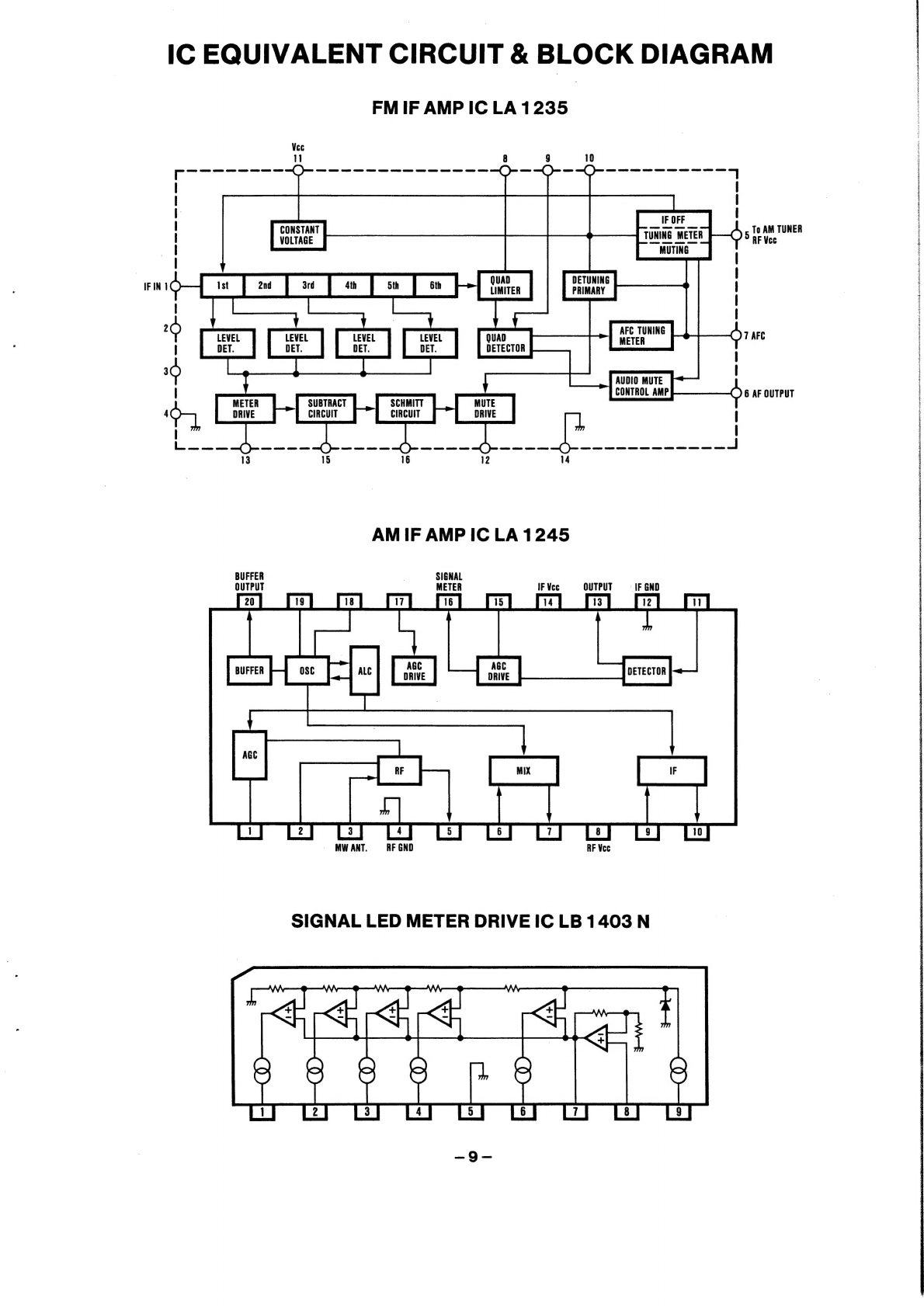
LA1235
LA3400
Dual
Gate
,
;
.
MOS
FET
Differential
Double
IF
Amp.
Right
WD)
rg
LA6458
AM
Loop
Antenna
AM
IF/DET
LA1245
Level
Meter
LB1403
-
Function
.
Control
LW
Remote
Control
Terminal
TC9303AN
4
Key
Matrix
Z
Remote
Control
;
:
-001
K—]
Transistor
K——)
MicroProcessor
K—————_—_—_——_
0
Z
Switch
TMP4270
|
|
15.6V
5.6V
—24V
c
&
~|1AMOSC
Control
LSI
PLL
resi7ip,
LA6458
7
coc
thet
etal
Lat
Lt
ht
:
:
Band/Preset
Digitron
Display
Control
Constant
Voltage
Regulator
Front
Panel
LA5666