ROHS EmCORE-i2709 User manual

- 1 -
Quick Installation Guide
Version 1.2
If you have any technical difculties, please consult the user’s manual rst at:
ftp://ftp.arbor.com.tw/pub/manual
Please do not hesitate to call or e-mail our customer service when you still can not
nd out the answer.
http://www.arbor.com.tw
E-mail: info@arbor.com.tw
♦ Technical Support
EmCORE-i2709
3.5" Compact Board
Form Factor
3.5" Compact Board
Video
Dual Channels 24-bit
LVDS/ Analog RGB
/
TV-out
I/O
Mini-PCI/ Mini-Card/
SATA/ USB/ COM/ LPT/
DIO
CPU
Soldered onboard Intel®
Atom™ N270 1.6GHz
Processor
LAN
2 x Realtek 8111 PCIe
Gigabit Ethernet
Audio
Realtek ALC655 AC97
Audio CODEC, Line-in/
Line-out/ Mic-in
Chipset
Intel® 945GSE
Intel® ICH7M
Copyright® 2011 All Rights Reserved. 4041270900120P
Declaration of Conformity
FCC Class A
This device complies with Part 15 of the FCC Rules. Operation is subject to the
following two conditions : (1) this device may not cause harmful interference, and
(2) this device must accept any interference received, including interference that
may cause undesired operation.

- 2 -
Ordering Information
EmCORE-i2709 Intel Atom™ N270 1.6GHz 3.5" Compact Board
FCDB-1293 4 x COM ports & digital I/O daughter board
CBK-11-2709-00
Cable Kit
1 x Audio Cable
2 x COM Port Cables
1 x IDE Cable
1 x KB & MS Cable
2 x LAN Cables
1 x LPT to FDD Cable
1 x Parallel Port Cable
2 x SATA Cables
1 x TV-out Cable
3 x USB Cables
1 x VGA Cable
Packing List
Before you begin installing your Compact Board, please make sure that the following
materials have been shipped:
1 x EmCORE-i2709 3.5" Compact Board with heat sink
1 x Driver CD
1 x Quick Installation Guide
If any of the above items is damaged or missing, contact your vendor immediately.
The Installation Paths of CD Driver
Windows 2000 & XP
Driver Path
CHIPSET \CHIPSET\INF 9.11
LAN \ETHERNET\REALTEK\8111_WINXP_5764
VGA \GRAPHICS\INTEL_2K_XP_32\1432
AUDIO \AUDIO\REALTEK_AC97\Win2K_XP_A406

- 3 -
Form Factor 3.5" Compact Board
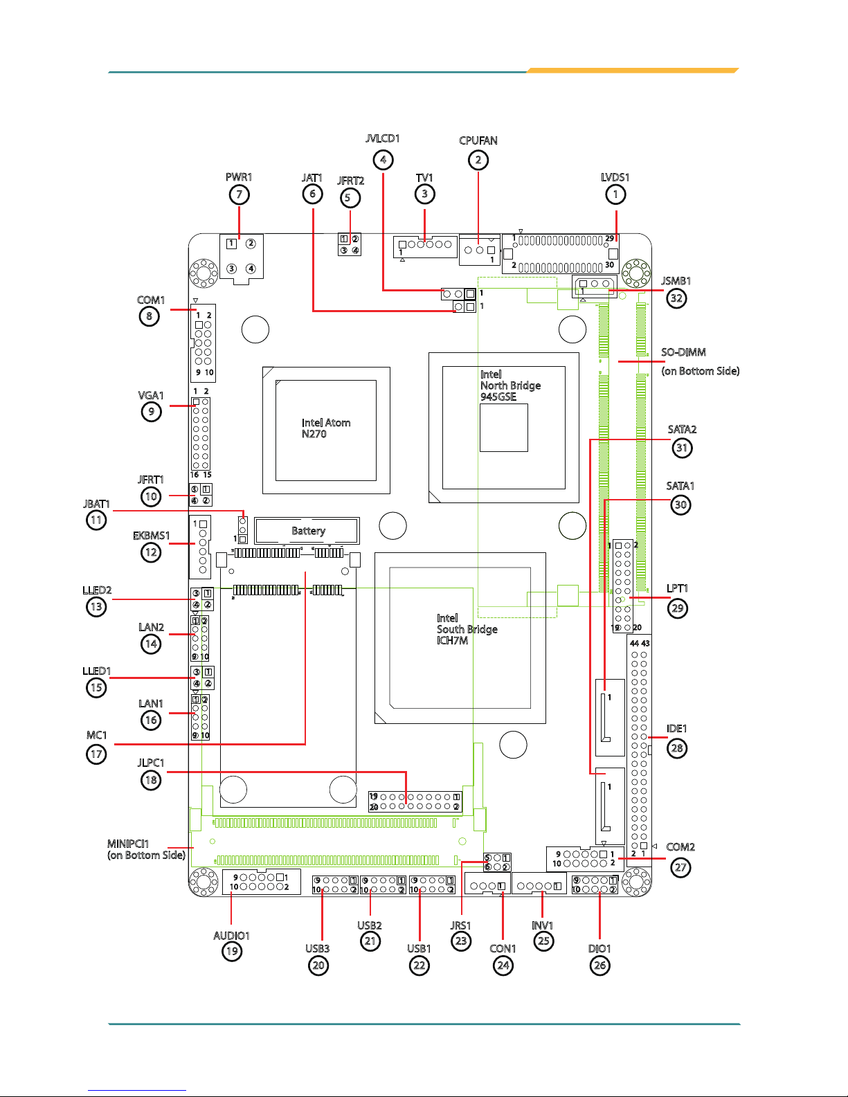
CPU Intel® Atom™ N270 CPU 1.6GHz with 533MHz FSB
Chipset Intel® 945GSE + Intel® ICH7M
System Memory 1 x 200-pin SO-DIMM Socket Up to 2GB DDR2 533MHz
SDRAM (Bottom side)
VGA/ LCD
Controller
Integrated Intel Graphics Media Accelerator 950, Dual
Channels 24-bit LVDS
Ethernet 2 x Realtek 8111 PCIe Gigabit Ethernet controllers
I/O Chips Winbond W83627HG
BIOS AMI PnP Flash BIOS
Audio Realtek ALC655 AC97 Audio CODEC, MIC-in/ Line-In/ Line-
Out
Storage
2 x Serial ATA 150MB/s HDD transfer rate
1 x IDE Ultra ATA 33, support 2 IDE devices
1 x Floppy connector share with LPT port
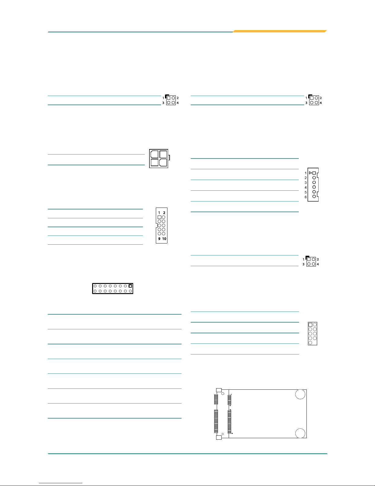
Serial Port 2 x COM ports
(COM1: RS-232, COM2: RS-232/422/485 selectable)
Parallel Port 1 x LPT Port (SPP/EPP/ECP mode selectable)
KBMS One 6-pin wafer connector (PS/2 interface Keyboard and
Mouse via cable)
Universal Serial Bus 6 x USB 2.0 ports
Digital I/O 8-bit programmable Digital Input/Output
Expansion Interface 1 x Mini-Card Slot
1 x Mini PCI Socket (Bottom side)
Operation Temp. -20oC ~ 70oC (-4oF ~ 158oF)
Watchdog Timer 1~255 levels Reset
Dimension (L x W) 146 x 102 mm ( 5.7" x 4.0" )
Specications
Windows 7
Driver Path
CHIPSET \CHIPSET\INF 9.11
LAN Windows 7 built-in LAN driver
VGA \GRAPHICS\INTEL_WIN7_32\1930
AUDIO \AUDIO\REALTEK_AC97\Win7_32_64_6305

- 4 -
Board Dimensions
Top View
1
1
3
1
1
1
10
9
2 2
1
1
1
1
1
1
1
1
1
6 4
1
2
1
31.80
8.84
142.77
146.00
3.17
98.78
101.96
21.97
SO-DIMM MIni PCI
11.30
6.50
Battery
-21.60
Unit: mm

- 5 -
Bottom View
1
47.12
32.80
8.84
98.57
Ø6.35
Ø3.10
Unit: mm

- 6 -
Jumpers/ Connectors Quick Reference
Jumpers
Label Function
JAT1 AT/ATX Power Mode Selection
JBAT1 Clear CMOS Setting
JRS1 COM2 RS-232 / 422 / 485 Selection
JVLCD1 LCD Voltage Selection
Connectors
Label Function
AUDIO1 Audio Connector
COM1 RS-232 Connector
COM2
RS-232/422/485 Connector
CON1 RS-422/485 Connector
CPUFAN Fan Power Connector
DIO1 Digital I/O Connector
IDE1 IDE Connector
INV1 LCD Inverter Connector
JFRT1 Switch
JFRT2 LED indicators
JLPC1 Low Pin Count Connector
JSMB1 External SMBus Connector
EKBMS1 Keyboard & Mouse Connector
LAN1 ~ 2 Ethernet Connectors
LLED1~ 2 LAN LED Indicators
LPT1 Parallel Port or FDD Connector
LVDS1 LVDS LCD Connector
MC1 PCI Express Mini-Card Slot
MINIPCI1 Mini-PCI Socket (bottom side)
PWR1 +12V Power Connector
SATA1~2 Serial ATA Connectors
TV1 TV-out Connector
USB1~3 USB Port Connectors
VGA1 Analog RGB Connector

- 7 -
Jumpers & Connectors Location
1
2
40
39
42
41
200
199
123 124
2
1
52
51
16
18
15
17
2
1
1
2
5
6
20
1
1
1
1
1
1
1
1
3
42
1
3
42
9 10
16 15
1
1
11
11
1
2
2
1 2
3 4
29
30
2
19 20
2
4344
1
92
2
10
1
9
2
10
1
3
1
Battery
Intel
South Bridge
ICH7M
Intel Atom
N270
Intel
North Bridge
945GSE
LVDS1
1
CPUFAN
2
TV1
3
JVLCD1
4
JAT1
6
PWR1
7
COM1
8
VGA1
9
JFRT1
10
EKBMS1
12
LLED2
13
LAN2
14
LLED1
15
LAN1
16
MC1
17 JLPC1
18
JBAT1
11
AUDIO1
19 USB3
20
USB2
21 USB1
22
JRS1
23 CON1
24
INV1
25 DIO1
26
COM2
27
IDE1
28
LPT1
29
SATA1
30
31
SATA2
JSMB1
32
SO-DIMM
(on Bottom Side)
9 10
1 2
1
3
42
9 10
1 2
9
10 9
10
1
21
2
9
10
1
2
9
19
10
111
1
2
2
MINIPCI1
(on Bottom Side)
1
34
2
JFRT2
5

- 8 -
Jumpers Connectors
JBAT1: Clear CMOS Setting (11)
Connector type: 2.00mm pitch 1x3-pin headers.
Pin Mode
1-2 Keep CMOS (Default)
23 1
2-3 Clear CMOS
23 1
JVLCD1: LCD Panel Voltage Selection (4)
The voltage of LCD panel could be selected by
JVLCD1 in +5V or +3.3V.
Connector type: 2.54mm pitch 1x3-pin headers.
Pin Voltage
1-2 +5V
23 1
2-3 +3.3V (Default)
23 1
JRS1: COM2 RS-232/422/485 Selection (23)
Connector type: 2.00mm pitch 2x3-pin headers.
Mode RS-232
(Default) RS-422 RS-485
1-2 Short Open Open
3-4 Open Short Open
5-6 Open Open Short
65
2
1
65
2
1
65
2
1
LVDS1: LVDS LCD Connector (1)
Connector type: DF-13-30DP-1.25V connector and
supports 24-bit dual channels.
Pin Desc. Pin Desc.
1
2930
2
2 VDD 1 VDD
4TX2CLK+ 3 TX1CLK+
6 TX2CLK- 5 TX1CLK-
8 GND 7GND
10 TX2D0+ 9TX1D0+
12 TX2D0- 11 TX1D0-
14 GND 13 GND
16 TX2D1+ 15 TX1D1+
18 TX2D1- 17 TX1D1-
20 GND 19 GND
22 TX2D2+ 21 TX1D2+
24 TX2D2- 23 TX1D2-
26 GND 25 GND
28 TX2D3+ 27 TX1D3+
30 TX2D3- 29 TX1D3-
CPUFAN: Fan Power Connector (2)
CPUFAN is a 3-pin headers for the CPU fan. The fan
must be a +12V fan.
Pin Description
1
2
3
1GND
2+12V
3 FAN_Detect
TV1: TV-out Connector (3)
Connector type: 2.00mm pitch 1x6-pin box wafer
connector
Composite Video
1CVBS 2GND
3Unused 4GND
5Unused 6 GND
S-Video
1Unused 2GND
3Luminance 4GND
5Chrominance 6 GND
JAT1: AT/ATX Power Mode Selection (6)
Connector type: 2.54mm pitch 1x2-pin headers.
Pin 1-2 Power Mode Selection
Short AT Mode
1 2
Open ATX Mode
(Default)
1 2
Note:
To activate the ATX power mode, you must turn
on the power button switch rst (The connector for
power button swtich is located in JFRT1).

- 9 -
COM1~2: RS-232 Connectors (8, 27)
Connector type: 2.00mm pitch 2x5-pin box headers.
Pin Desc. Pin Desc.
9 10
1 2
1 DCD# 2 RXD
3 TXD 4 DTR#
5 GND 6 DSR#
7RTS# 8 CTS#
9 RI# 10 N/C
PWR1: +12V Connector (7)
PWR1 supplies CPU operation at +12V (Vcore).
Pin Desc. Pin Desc.
24
13
2GND 4+12V
1GND 3 +12V
MC1: Mini-Card Socket (17)
52
16
18
2
VGA1: Analog RGB Connector (9)
Connector type: 2.00mm pitch 2x8-pin headers.
1
2 16
15
Pin Description Pin Description
1 RED 2 GREEN
3 BLUE 4N/C
5 Analog RGB_GND 6 Analog RGB_GND
7Analog RGB_GND 8 Analog RGB_GND
9Analog RGB_VCC 10 Analog RGB__Detect
11 N/C 12 DDC_DATA
13 HSYNC 14 VSYNC
15 DDC_CLOCK 16 N/C
EKBMS1: Keyboard & Mouse Connector (12)
Connector type: 2.0mm pitch 1x6-pin box wafer
connector.
Pin Description
1KB_DATA
2GND
3 MS_DATA
4KB_CLK
5 KB_VCC
6 MS_CLK
LLED1,2: LAN1/LAN2 LED Indicators (15, 13)
Connector type: 2.54mm pitch 2x2-pin headers.
Pin Description Pin Description
21
43
1 Active 2 +3V
3 +3V 4Link
LAN1,2: Ethernet Connectors (16, 14)
Connector type: 2.00mm pitch 2x5-pin headers.
Pin Desc. Pin Desc.
109
1 2
1TX+/ MDI0+ 2TX/ MDI0-
3RX+/ MDI1+ 4N/C/ MDI2+
5N/C/ MDI2- 6RX-/ MDI1-
7N/C/ MDI3+ 8N/C/ MDI3-
9N/C 10 N/C (Key)
JFRT1: Switch (10)
This connector provides signals for the system power
switch and reset.
Connector type: 2.54mm pitch 2x2-pin headers.
Pin Description Pin Description
21
43
1PWRBTN+ 2PWRBTN-
3 RESET+ 4RESET-
JFRT2: LED Indicators (5)
This connector provides signals for LED indicators
presenting the status of the system.
Connector type: 2 .54 mm pitch 2x2 pin headers
Pin Description Pin Description
21
43
1PWRLED+ 2PWRLED-
3 HDDLED+ 4HDDLED-

- 10 -
DIO1: Digital I/O Connector (26)
DIO1 is a 8-bit DIO connector w/ onboard 10-pin
headers, supports programmable Input / Output.
Connector type: 2.00 mm pitch 2x5-pin headers
Pin Description Pin Description
109
1 2
1DIO0 2DIO1
3 DIO2 4DIO3
5 DIO4 6 DIO5
7DIO6 8 DIO7
9+5V 10 GND
AUDIO1: Audio Connector (19)
Connector type: 2.00mm pitch 2x5-pin box headers.
Pin Description Pin Description
9 10
1 2
1 Line Left In 2 Line Right In
3 GND 4GND
5 MIC1 6 MIC2
7GND 8 GND
9 Line-out Left 10 Line-out Right
CON1: RS-422/485 Connector (24)
Connector type: 2.00mm pitch 1x4-pin box wafer
connector.
Pin RS-422 RS-485
1
2
3
4
1TX+ DATA+
2TX- DATA-
3 RX+ N/C
4RX- N/C
INV1: LCD Inverter Connector (25)
Connector type: 2.00mm pitch 1x5-pin box wafer
connector.
Pin Description
1
2
3
4
5
1+12V
2GND
3 Backlight on/off
4Brightness control
5 GND
USB1~3: USB Connectors (22, 21, 20)
Connector type: 2.00mm pitch 2x5-pin headers.
Pin Desc. Pin Desc.
109
1 2
1+5V 2+5V
3 USBD- 4USBD-
5 USBD+ 6 USBD+
7GND 8 GND
9GND 10 N/C (Key)
JLPC1: Low Pin Count Connector (18)
Connector type: 2.00mm pitch 2x10-pin headers
Pin Desc. Pin Desc.
1 2
19 20
1CLK 2GND
3 LFRAME 4N/C
5 LRESET 6 N/C
7LAD3 8 LAD2
9+3.3V 10 LAD1
11 LAD0 12 GND
13 N/C 14 N/C
15 +3.3V_SB 16 SERIRQ
17 GND 18 CLKRUN
19 PD 20 N/C
I
DE1: Primary IDE Connector (28)
Connector type: 2.00mm pitch 2x22-pin box headers.
1
2
43
44
Pin Description Pin Description
1IDE RESET 2GND
3DATA7 4 DATA8
5 DATA6 6 DATA9
7DATA5 8 DATA10
9 DATA4 10 DATA11
11 DATA3 12 DATA12
13 DATA2 14 DATA13
15 DATA1 16 DATA14
17 DATA0 18 DATA15
19 GND 20 N/C
21 REQ 22 GND
23 IO WRITE 24 GND
25 IO READ 26 GND
27 IO READY 28 IDSEL
29 DACK 30 GND
31 IRQ14 32 N/C
33 ADAD1 34 ATA66 DETECT
35 ADAD0 36 ADAD2
37 CS#1 38 CS#3
39 IDEACT 40 GND
41 +5V 42 +5V
43 GND 44 N/C

- 11 -
SATA1~2: Serial ATA Connectors (30, 31)
High speed transfer rates (150MB/s).
Pin Description
1
7
1GND
2TX+
3 TX-
4GND
5 RX-
6 RX+
7GND
JSMB1: External SMBus Connector (32)
Connector type: 2.54mm pitch 1x3-pin box wafer
connector.
Pin Description
1
2
3
1 Data
2Clock
3 SMB_Alert#
MINIPCI1 : Mini-PCI Socket (bottom side)
Parallel port connector is shared with FDD.
Pin Description Pin Description
1N/C 2RWC#
3 RINDEX# 4HEAD#
5 TRACK0# 6 DIR#
7WP# 8 STEP#
9 RDATA# 10 GND
11 DSKCHG# 12 GND
13 N/C 14 N/C (Key)
15 N/C 16 MOB#
17 N/C 18 WD#
19 DSB# 20 WE#
LPT1: Parallel Port or FDD Connector (29)
Pin Description Pin Description
1STROBE# 2 AFD#
3PTD0 4 Error#
5PTD1 6INIT#
7 PTD2 8 SLIN#
9PTD3 10 GND
11 PTD4 12 GND
13 PTD5 14 N/C (Key)
15 PTD6 16 Busy
17 PTD7 18 PE
19 ACK# 20 Select
Connector type: 2.00 mm pitch 2x10-pin headers
It can be selected by LPT or FDD mode via BIOS.
1
2
19
20
DIMM1 : SO-DIMM Socket (bottom side)
1
240
39
42
41
200
199

- 12 -
This page is intentionally left blank.
Table of contents
Other ROHS Motherboard manuals