ROKAMAT Tigris 850 User manual

1) Rokamat Tigris 850 (22TI85001)
2) 2014/30/EU, 2006/42/EG, 2012/19/EU, 2011/65/EU,
2001/95/EG, EG No. 1907/2006
3) EN 62841-1:2015+AC:2015, EN ISO 12100:2010
4) Kammerer GmbH, An der B 10, 75196 Remchingen
Remchingen, 01.03.2023
Beate Kammerer
Head of Technical Documentation
EN
Original Instructions
4
Tigris 850
Art.-Nr. 53000
© Kammerer GmbH. Printed in Germany. Abbildungen unverbindlich.
Technische Änderungen vorbehalten. BA_Tigris 850_EN_007
ROKAMAT
Kammerer GmbH
An der B 10
75196 Remchingen
Deutschland
www.rokamat.com

Tigris 850
2
11
[1]
1-1
1-4
1-6
[3]
[2]
1-2
[5]
[6]
5-3
3-1
I
0
4-1
[4]
6-1
6-2
1-7
2-1
1-5
A
B
C
2-2
5-1
5-2
1-9
2-3
1-8
1-3

Tigris 850
3
[7]
[9]
[10]
[8]
A
B
C
7-2
7-3
8-1
7-4
7-1
10-1
10-2
A
B
9-1
9-2
D
10-4
10-3

Tigris 850 en English
4
1. Symbols .........................................................................4
2. Safety Instructions ....................................................4
3. Intended Use ................................................................4
4. Technical Specifications .......................................... 5
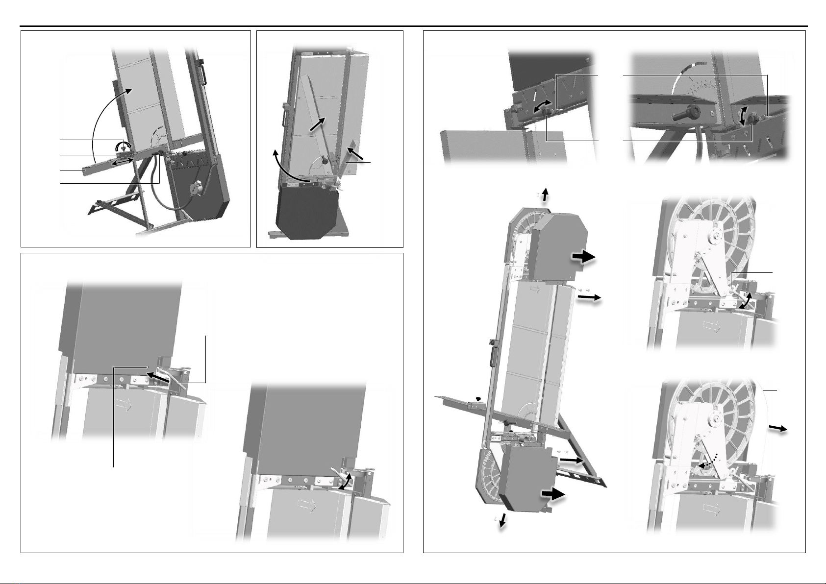
5. Device Components................................................... 5
6. Commissioning............................................................ 5
7. Instructions for Use................................................... 5
8. Maintenance and Care.............................................. 6
9. Spare Parts and Accessories.................................. 6
10. Environmental Protection....................................... 6
11. Declaration of Conformity....................................... 6
12. Troubleshooting ......................................................... 6
For your own protection and for the protec-
tion of your power tool, pay attention to all
parts of the text that are marked with this
symbol!
Risk of electric shock!
Warning of hand injuries! *)
Read operating instructions and safety no-
tices! *)
Wear protective goggles!
Wear ear protection!
Wear hand protection!
Wear a dust mask! *)
CAS Li-Ion battery pack
Removing battery pack!
Do not dispose of as domestic waste! *)
Important advice/information
Direct Current (DC) *)
Confirms the conformity of the power tool
with the directives of the European Com-
munity. *)
Confirms the conformity of the power tool
with UK legislation. *)
*)These symbols are (also) on the device.
For your safety
Read all safety warnings and instructions.
Failure to follow all safety warnings and in-
structions may result in electric shock, fire
and/or serious injury.
Do not use this power tool before you have
thoroughly read and completely understood
this Instruction Manual, the enclosed “Gen-
eral Safety Instructions”, instructions for bat-
tery packs and chargers.
Keep all safety instructions and information for
future reference. Pass on your power tool only to-
gether with these documents.
Please also observe the relevant national indus-
trial safety regulations.
Safety instructions for wire saws
Do not reach into the area of the saw wire when the
tool is switched on.
Only make the saw cuts using the handle provided
for this purpose and at the same time secure the
workpiece (insulation material) by hand.
Only use suitable materials.
If the impeller tensioner is already at the end stop,
the impellers must be switched.
If the cutting speed decreases, the saw wire should
be replaced.
A damaged or worn saw wire must not be used.
If the saw wire jams in the workpiece (insulation
material), switch off the motor immediately. Before
switching on again, the saw wire must be able to
rotate freely again.
Before operating the wire saw, check that it is sta-
ble and that all machine parts are assembled cor-
rectly, especially all protective devices. Also check
that the saw wire and impellers are in good condi-
tion and that the saw wire is sufficiently tensioned.
Additional safety instructions
Particles generated when working with this ma-
chine may contain substances that can cause can-
cer, allergic reactions, respiratory diseases, birth
defects or other propagation defects. Some of
these substances include: mineral dust (from min-
eral wool, aerated concrete or similar), styrene, etc.
The risk depends on for how long the user or near-
by persons are exposed to the substance.
This dust must not be allowed to enter your body.
Do the following to reduce exposure to these sub-
stances:
- Ensure good ventilation of the workplace
- To protect your health, wear a suitable
protective mask.
- Always wear protective goggles to protect
against sanding hazards.
- Connect the electric power tool to a suitable ex-
traction system.
- Sweeping or blowing stirs up dust.
- Vacuum or wash the protective clothing. Do not
blow, beat or brush.
Collect the generated particles at the source, avoid
deposits in the surrounding area.
Always use an antistatic suction hose with the
power tool. A slight electric shock may cause you to
panic briefly and become distracted, which may re-
sult in an accident.
switch off the machine immediately when the
safety clutch responds and if the saw wire breaks!
Do not overload the motor for a long period. Engine
noise should be regular (not wave-like). Unsteady
engine performance can be perceived acoustically.
Take a break when the machine is heated up
strongly and let it cool down again. To that let the
motor idle at top speed for some time.
Don’t bend the flexible drive shaft!
Only use original Rokamat saw wire. Foreign mate-
rials are not suitable for the saw wire speed and
applications of the wire saw and could tear.
Emission levels
NOTE! Values for the A-weighted sound pressure
level and for the total vibration values can be found
in the “Technical specifications” table at page 5.
The vibration emission level given in this infor-
mation sheet has been measured in accordance
with a standardized test and may be used to com-
pare one tool with another. It may be used for a
preliminary assessment of exposure.
CAUTION! The indicated measurements refer to
new power tools. Daily use causes the noise and vi-
bration values to change.
The declared vibration emission level represents
the main applications of the tool. However, if the
tool is used for different applications, with differ-
ent accessories or poorly maintained, the vibration
emission may differ. This may significantly in-
crease the exposure level over the total working
period. However, if the tool is used for different ap-
plications, with different accessories or poorly
maintained, the vibration emission may differ. This
may significantly decrease the exposure level over
the total working period.
CAUTION! The noise produced during work
may damage your hearing.
Wear ear protection!
Environmental conditions
Operation
Temperature range: +5° C to +50° C
Humidity: ≤ 85 %, non-condensing
Climate: dry
Transport and storage
Temperature range: -5° C to +55° C
Humidity: 0 % to 70 %
Climate: dry, roofed, dew protected
The portable Rokamat Tigris 850 cordless wire
saw is intended exclusively for cutting insulation
materials and plasterboard at angles of 30°-90°.
Insulation materials up to a max. thickness (cutting
depth) of 320 mm, a max. width (cutting length) of
1200 mm and a max. density of 650 kg/m³ can be
cut using only the Rokamat special saw wire. and
may only be operated with an external dust extrac-
tion device.
The transportable wire saw must be set up on a
level and solid surface and may only be operated
with an external dust extraction device.
Only sufficiently qualified and trained personnel
may carry out activities with the Tigris.
The intended use includes the observance of the
operating instructions, in particular the safety in-
structions and the observance of generally recog-
nized accident prevention regulations.
The manufacturer is not liable for damage caused
by non-intended use of the tool.
1. Symbols
2. Safety Instructions
WARNING!
3. Intended Use
⎓
Contents
X
DEUTSCH de

Tigris 850 en English
5
Cordless wire saw Tigris 850
Art.-Nr. 53000
Rated voltage
18 V DC
Maximum saw wire
speed
37000 mm/s
Total weight
26,5 kg
Space requirement
ca. 1,2 m2
Cutting length
max. 850 mm
Board thickness
max. 340 mm
Dimension compact
(LxHxW)
560x1850x200 mm
Dimension set up
(LxHxW)
1128x1880x1015 mm
A-weighted sound pressure level (see cap. 2
“Emission levels“):
Sound pressure level LpA
87 dB(A)
Sound power level LWA
92 dB(A)
Uncertainty KpA, KWA
3,0 dB
Total vibration value (see cap. 2 “Emission
levels “):
Emmission value ah
< 2,5 m/s2
Uncertainty K
1,5 m/s2
The specified illustrations can be found in Fig. [1]
on page 2 of the operating manual.
1-1 Top cover
1-2 Cutting bow
1-3 Support plate
1-4 Handle
1-5 Motor housing
1-6 Stand
1-7 Mitre gear
1-8 Stabilising arm
1-9 Bottom cover
Before switching on the power tool: Unpack
power tool and accessories and check that no
parts are missing or damaged.
Setting up the wire saw [2]
Risk of injury! Danger of tipping!
The portable wire saw must be set up on a level
and firm surface.
With stand
ALoosen the star grip screw [2-1] on the top of
the back of the wire saw. Fold down the stand
[1-6].
BFix the stand [1-6] underneath the motor hous-
ing [1-5] using the star knob screw [2-1]. Loosen
the star screw [2-2] of the stabilising arm [1-8]
and then fold it down.
CFix the stabilising arm [1-8] on the stand using
the star screw [2-2].
Assembly on the frame
Alternatively, the Tigris can also be mounted on a
frame. To do this, place the unit upright on the scaf-
fold (leave the stand and anti-tip guard in the start-
ing position - as in Fig. [2 A]). Then lash the main
beam [2-3] to the rear of the frame using the two
lashing straps supplied. Check that it is securely
held!
Connecting the dust extraction system [3]
Push the suction hose onto the intake socket [3-1].
Check for correct fit! If necessary, use a suitable
adapter. See also chapter 7: “Dust extraction”.
Switching the electric power tool on and off
[5]
Switching on: Insert the charged battery pack [5-1].
Set the toggle switch on the housing [5-3] to I.
Switching off: Set the toggle switch on the housing
[5-3] to 0.
Risk of injury, electric shock!
Always remove the battery pack before per-
forming any type of work on the machine!
Installing or removing battery pack [5]
To insert: Push the battery pack [5-1] on the back
of the wire saw onto the battery fixing until it en-
gages.
To remove: Press the battery lock [5-2] down and
pull out the battery pack [5-1] upwards.
Starting the wire saw [4]
Switching the electric power tool on (see “Switch-
ing the electric power tool on and off”in chapter 6).
To start the wire saw (cutting), keep button [4-1] on
handle [1-4] pressed - the saw wire starts moving.
Release the button [4-1] again to stop the saw wire.
Foot switch (optional)
Instead of the button [4-1] on the handle, the wire
saw can also be started with the foot switch (op-
tionally available).
First, the foot switch must be connected to the
socket of the motor housing [1-5]. Then press the
foot switch to start the wire saw.
If the foot switch is no longer actuated, the saw
wire comes to a standstill again.
Adjusting the cutting angle
Mitre cuts [6]: Loosen the quick release top [6-1]
and bottom [6-2], adjust the cutting bow [1-2] to
the desired angle (see mitre indicator), fix the quick
release [6-1 and 6-2] again.
Bevel cuts [7]: To move the support angle [7-3],
loosen the star grip screw [7-4], set the desired an-
gle (see scale on the support plate [1-3]) and
tighten the star grip screw [7-4] again.
Width stop [7]
For quick cutting repetition, the desired dimension
can be set on the support angle using the end stop
[7-2].
To do this, loosen the star screw [7-1], move the end
stop [7-2] to the desired position and tighten the
star screw [7-1] again.
Width stop [10-A]
Move out the cutting bow [1-2]. Loosen the star grip
screw [10-2] at the top and bottom and slide the
depth limit to the desired dimension (see scale on
the cutting bow). Then retighten the star grip
screws [10-2]. Now move the cutting bow [1-2] to
the end stop and loosen the fixing bolts [10-1] at the
top and bottom by turning them, push them to the
right and engage them by turning them again.
Sawing insulating material
Damage to the wire saw!
Always push the insulation material through
from left to right!
Place the insulation material on the support plate
[1-3] and make all necessary adjustments. Activate
the wire saw (see "Starting the wire saw"). The cut-
ting bow [1-2] can be moved using the handle [1-4].
It is possible to cut both by pushing and pulling the
cutting bow [1-2]. In addition, if the cutting bow
[1-2] is fixed (see "Depth limit"), the insulation ma-
terial can also be pushed from left to right in order
to cut it horizontally.
Changing the saw wire [9]
Over time, the tension of the saw wire may de-
crease. In this case, perform the following steps:
AInsert the enclosed Allen wrench [9-1] into the
opening [9-2] of the top cover [1-1] and turn the
clamping screw inside counterclockwise. This
allows the spring to tension the saw wire again.
BThen tighten the clamping screw clockwise
again.
Changing the saw wire [10]
ALock the cutting bow [1-2] using the star grips
[10-2] between a height of 60-100 mm and ex-
tend the fixing bolt [10-1] (see “Width stop”).
BLoosen the screws of the top and bottom co-
vers [1-1 and 1-9] and remove the covers.
C Use the enclosed Allen wrench to loosen the
clamping screw [10-3] to be able to move the
clamping device.
DPut (worn) saw wire [10-4] over the impellers
to remove it.
Install the new saw wire in reverse order.
Risk of injury! Warning of hand injuries!
Wear gloves when changing the saw wire to
avoid cutting yourself!
6. Commissioning
7. Instructions for Use
4. Technical Specifications
5. Device Components
WARNING!
CAUTION!
X
CAUTION!
WARNING!
CAUTION!

Tigris 850 en English
6
Dust extraction
Health hazard posed by dust!
Where required, always work with an extraction
system and wear a protective mask. Observe
national regulations.
The dust extraction system offered on our website
is adapted to the quantity of dust generated and
permanently ensure the necessary suction power.
Transport [7 + 8]
To prepare the wire saw for transport, fold up the
right support bracket [8-1], set the left support
bracket [7-3] to 90° and the cutting bow [1-2] to 0°
(fold in). Fold up the stabilising arm [1-8] and then
the stand [1-6] and fix them in place.
Fuse replacement
Danger of voltage flashover!
Risk of injury, electric shock!
It is essential to remove the battery before re-
placing the fuse in order to avoid an uninten-
tional voltage flashover!
Remove the defective blade fuse from the holder in
the motor housing [1-5] and replace it with a new
one (with 35 A).
Risk of injury, electric shock!
Always be sure that the tool is switched off and
the battery pack is removed before performing
maintenance work on the machine!
Repairs may be carried out by an authorized cus-
tomer service center only.
Regularly check the impellers to avoid danger and
have them replaced by an authorized service work-
shop if they are damaged.
The power tool, especially the controls and inner
lining of the impellers, should be cleaned regularly,
often and thoroughly through all air vents using a
vacuum cleaner or by blowing in dry air. Prior to this
operation, separate the power tool from the power
source and wear protective glasses and dust mask.
Check all wearing parts once a month.
Other accessories, in particular insertion tools, can
be found in the manufacturer’s catalogues. Ex-
ploded drawings and spare-part lists can be found
on our homepage: www.rokamat.com.
Use only original Rokamat spare parts and work
tools.
The generated sawing dust may contain harmful
substances. Dispose appropriately.
Observe national regulations on environmentally
compatible disposal and on the recycling of dis-
used machines, packaging and accessories.
For Great Britain and EU countries: Do not
dispose of electric equipment or battery
pack together with household waste mate-
rial! In observance of the European Direc-
tives, on Waste Electric and Electronic
Equipment and Batteries and Accumulators
and Waste Batteries and Accumulators and
their implementation in accordance with
national laws, electric equipment and bat-
teries and battery pack(s) that have
reached the end of their life must be col-
lected separately and returned to an envi-
ronmentally compatible recycling facility.
Please ask your dealer about disposal options!
It is expressly declared that the cordless wire saw
listed on the first page under 1) from the indicated
serial no. complies with all relevant provisions
2) and that the harmonized standards listed in 3)
have been applied. The technical documentation is
available from the authorized documentation
agent named in 4).
Risk of injury!
Transport and storage of the power tool only in
the carry bag. Keep these out of the reach of
children. Children may suffocate or be strangled
when playing with the carry case.
Problem
Possible causes
Remedy
Motor runs, but the saw
wire does not turn.
Shaft core broken.
Exchange shaft core.
Mitre gear is defective.
Replace mitre gear.
Motor power fluctuates.
Carbon brushes worn.
Replace carbon brushes.
Tigris not working.
Battery discharged.
Charge battery.
Machine overloaded. Fuse blown.
Replace fuse.
Saw wire vibrates or has
too little tension.
Not enough tension.
Tension the saw wire again.
Cutting speed decreases.
Saw wire worn out.
Remove blockage.
Extraction power is insuf-
ficient.
Suction nozzle blocked.
Clean the filter element regularly.
8. Maintenance and Care
WARNING!
WARNING!
9. Spare Parts and Accessories
ADVICE!
10. Environmental Protection
ADVICE!
12. Declaration of Conformity
12. Troubleshooting
If problems other than those listed occur, please contact your ROKAMAT service workshop or your local
specialist.
Li-Ion
X
WARNING!
X
WARNING!
This manual suits for next models
1
Table of contents
Popular Saw manuals by other brands

Power first
Power first Diamond Wheel Benchmount Saw owner's manual

Flex
Flex SKE2902VV Original operating instructions

Powermatic
Powermatic PM2000B Operating instructions and parts manual

Stihl
Stihl TS 480i instruction manual

Hitachi Koki
Hitachi Koki C 10RB Instruction manual and safety instructions

QEP
QEP 83012 owner's manual

Lumag
Lumag STM450-700 Operator's manual

Parkside
Parkside PZKS 1500 A1 Operating and safety instructions

Campbell Hausfeld
Campbell Hausfeld DG411200CK Operating instructions and parts manual

Graphite
Graphite 59G823 manual

Dexter Laundry
Dexter Laundry 900RPS2-200.5AB1 instruction manual

Worx
Worx WX437L.X manual