2
CUT 250CUT 250
CUT 250CUT 250
CUT 250
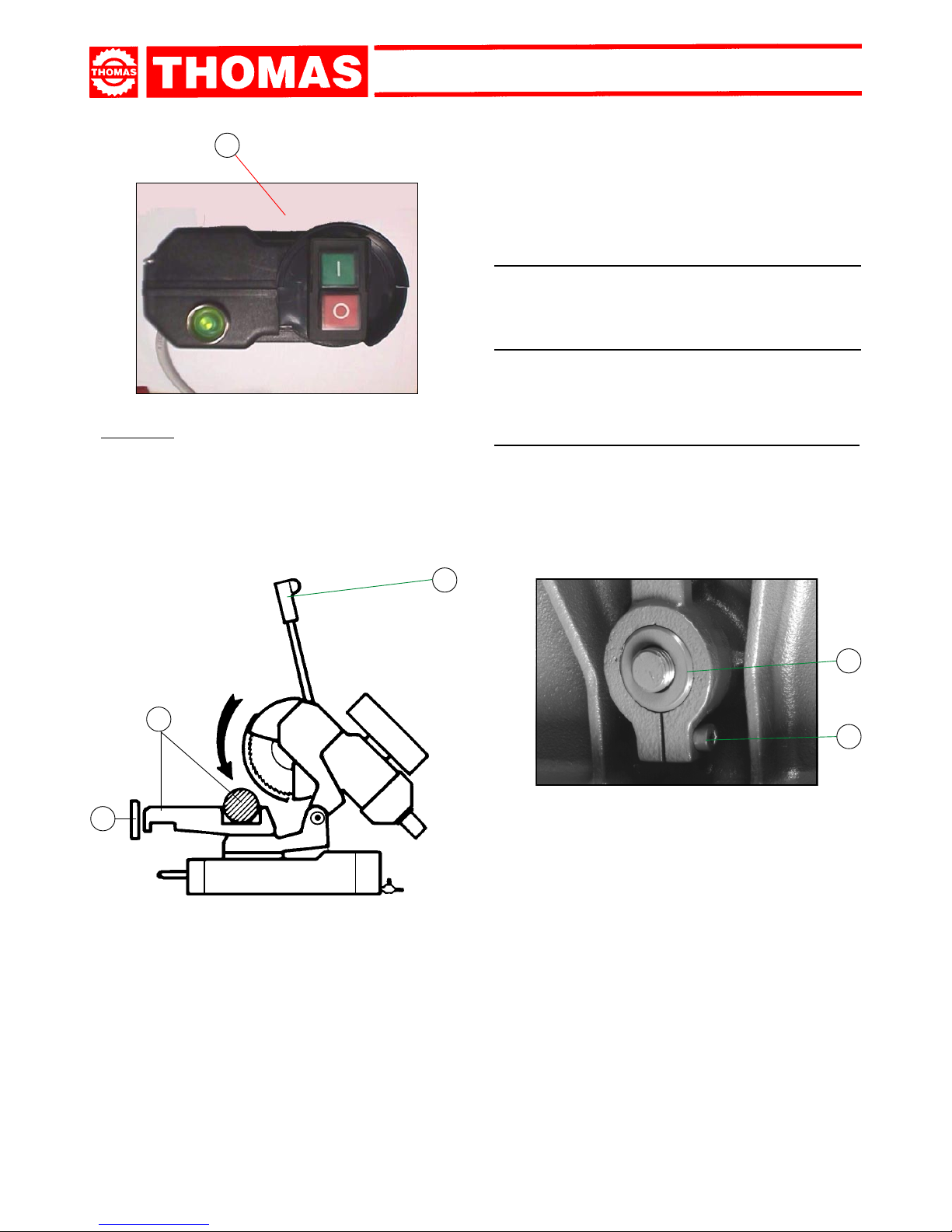
CHAPTER 7
Regulating the machine ............................................... " 7
7.1 - Disk head ................................................................" 7
7.2 - Vice ........................................................................." 7
7.3 - Regulating arm blockage........................................" 7
7.4 - Changing the disk..................................................." 8
7.5 - Changing the lubricating coolant pump.................." 8
CHAPTER 8
Routine and special maintenance .............................. " 8
8.1 - Daily maintenance .................................................." 8
8.2 - Weekly maintenance .............................................." 8
8.3 - Monthly maintenance ............................................." 8
8.4 - Six-monthly maintenance ......................................." 8
8.5 - Oil disposal ............................................................." 9
8.6 - Special maintenance .............................................." 9
CHAPTER 9
Material classification and choice of tool.................. " 9
9.1 - Definition of materials ............................................." 9
9.2 - Choosing the disk ..................................................." 9
9.3 - Teeth pitch .............................................................." 10
9.4 - Cutting and advance speed...................................." 10
9.5 - Running in the disk ................................................." 10
9.6 - Disk structure.........................................................." 10
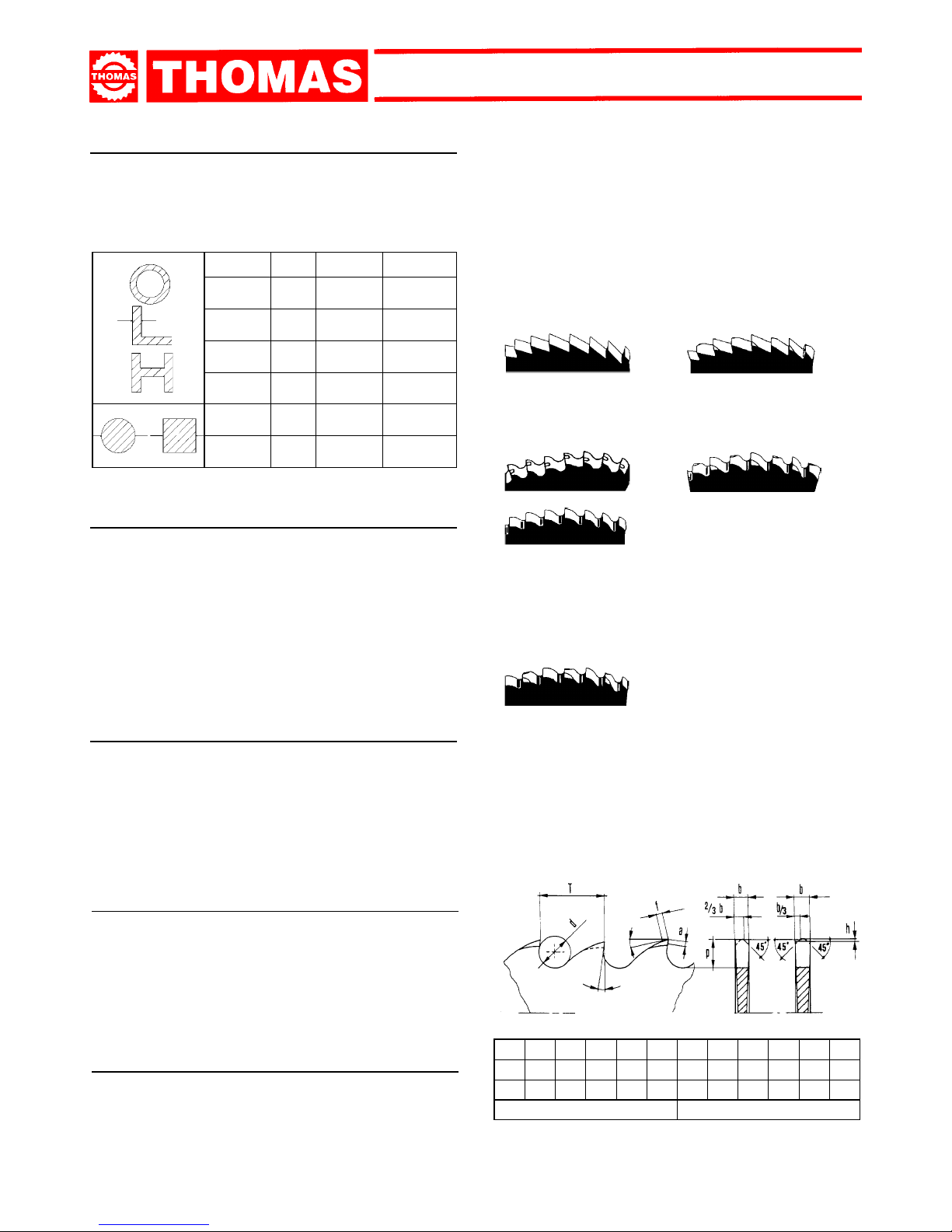
9.7 - Type of disks ..........................................................." 10
Tooth shape ..........................................................." 10
Tooth cutting angle................................................." 10
9.7.1 - Table of recommended cutting parameters ................. " 11
9.7.2 - Table of cutting speed according to disk diameter........ " 11
CHAPTER 10
Machine components ................................................... " 12
10.1- List of spare parts .................................................." 12
CHAPTER 11
Wiring diagrams ........................................................... " 14
CHAPTER 12
Troubleshooting ............................................................ " 15
12.1-Blade and cutting diagnosis...................................." 15
12.2-Electrical components diagnosis ............................" 17
CHAPTER 13
Noise tests..................................................................... " 17
Plates and labels .......................................................... " 18
Note ............................................................................... " 19
Contents
Contents ........................................................................ " 2
Ordering spare parts .................................................... " 2
Guarantee ...................................................................... " 2
Machine certification and identification marking.... " 3
CHAPTER 1
Reference to accident-prevention regulations.......... " 4
1.1 - Advice for the operator ..........................................." 4
1.2 - Location of shields against accidental contact with
the tool ...................................................................." 4
1.3 - Electrical equipment according to European
Standard "CENELEC EN 60 204-1" ..........."4
1.4 - Emergencies according to European Standard
"CENELEC EN 60 204-1" ..........................."4
CHAPTER 2
Recommendations and advice for use....................... " 4
2.1 - Recommendations and advice for using the machine "
4
CHAPTER 3
Technical characteristics............................................. " 5
3.1 - Table of cutting capacity and technical details ......." 5
CHAPTER 4
Machine dimensions - Transport - Installation
Dismantling ................................................................... " 5
4.1 - Machine dimensions ............................................... " 5
4.2 - Transport and handling of the machine.................." 5
4.3 - Minimum requirements for the premises
housing the machine .............................................." 5
4.4 - Anchoring the machine..........................................." 5
4.5 - Instructions for electrical connection ......................" 6
4.6 - Instructions for assembly of the loose parts and
accessories............................................................." 6
4.7 - Disactivating the machine......................................." 6
4.8 - Dismantling ............................................................." 6
CHAPTER 5
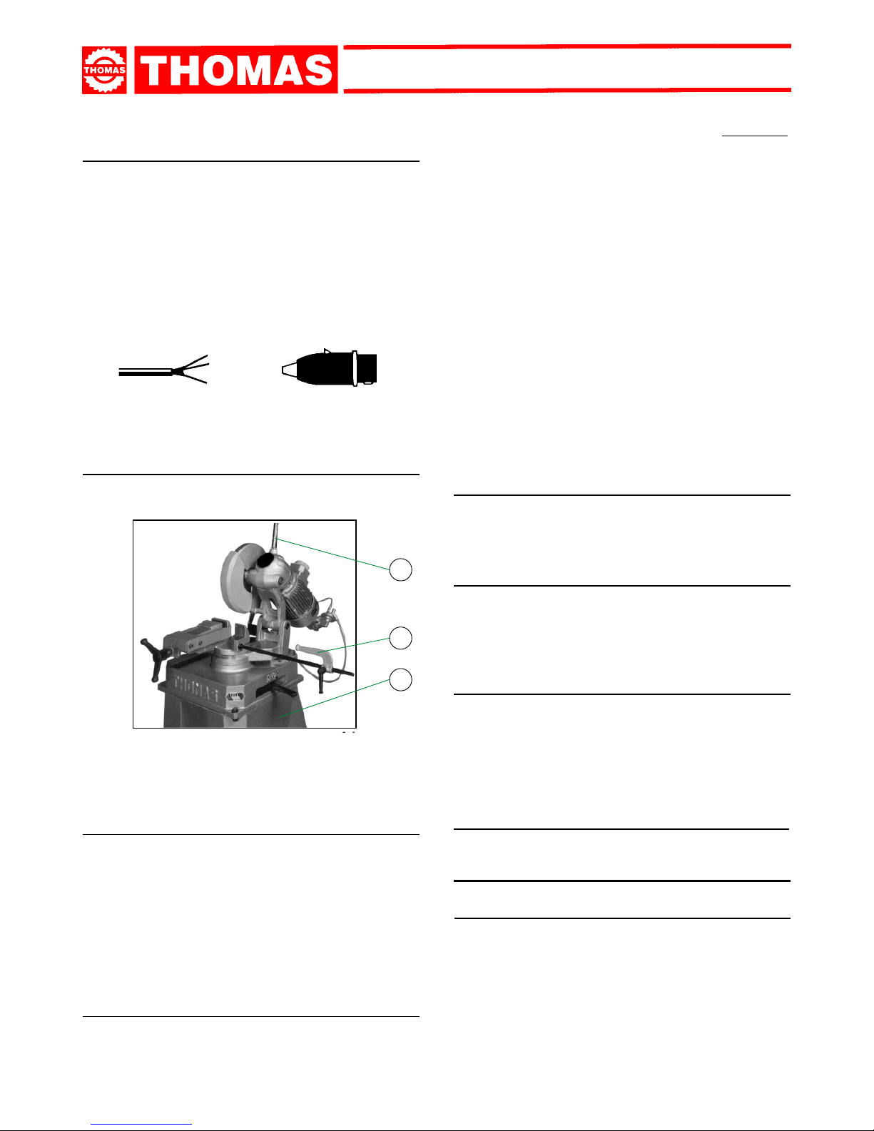
Machine functional parts ............................................. " 6
5.1 - Operating head ......................................................." 6
5.2 - Vice ........................................................................." 6
5.3 - Bed.........................................................................." 6
CHAPTER 6
Description of the operating cycle ............................. " 6
6.1 - Starting up and cutting cycle .................................." 6
Ordering spare parts
- When ordering spare parts you must state:
MACHINE MODEL
SERIAL NUMBER
PART REFERENCE NUMBER
Without these references WE WILL NOT SUPPLY the spares. See point 10.1 - list spare parts -.
Guarantee
- The Company guarantees that the machine to which this manual refers has been designed and built to comply with safety regulations
and that it has been tested for functionality in the factory.
- The machine is guaranteed for 12 months: the guarantee does not cover the electric motors, electric components, pneumatic
components or any damage due to dropping or to bad machine management, the failure to observe maintenance standards or bad
handling by the operator.
- The buyer has only the right to replacement of the faulty parts, while transport and packing costs are at his expense.
- The serial number on the machine is a primary reference for the guarantee, for after-sales assistance and for identifying the machine
for any necessity.