Product Overview
EVACOCM-01-V02-R3 Installation and Operation Manual AutoCharge:EV OpenCharge
December 2021 Page 4of 21
Product Overview
The AutoCharge:EV OpenCharge is an OCPP compliant, smart charging unit which has
been designed to provide the Host with full visibility and control of its use and, for the
driver, a simple to use EV charging solution activated via an RFID card/fob or an online
web or phone application which allows control of the unit and views of their charging
activity.
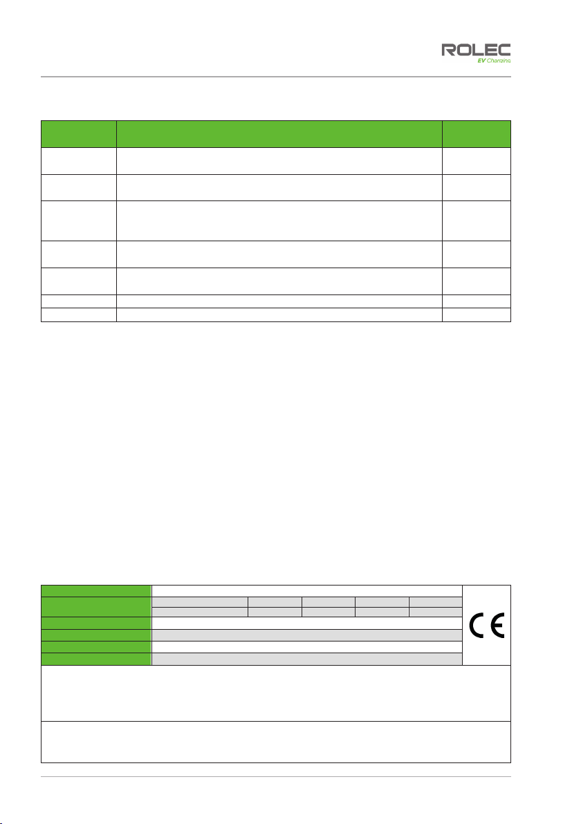
The AutoCharge:EV OpenCharge pedestal is available with the following power options:
Model Number Specification
OCPP0010 AutoCharge EV OpenCharge OCPP - 1x 3.6kW (16A) Type 2 socket
OCPP0011 AutoCharge EV OpenCharge OCPP - 1x 7.2kW (32A) Type 2 socket
OCPP0020 AutoCharge EV OpenCharge OCPP - 2x 3.6kW (16A) Type 2 sockets
OCPP0021 AutoCharge EV OpenCharge OCPP - 2x 7.2kW (32A) Type 2 sockets
OCPP0012 AutoCharge EV OpenCharge OCPP Superfast - 1x 11kW (16A) Type 2 socket
OCPP0013 AutoCharge EV OpenCharge OCPP Superfast - 1x 22kW (32A) Type 2 socket
OCPP0022 AutoCharge EV OpenCharge OCPP Superfast - 2x 11kW (16A) Type 2 sockets
OCPP0023 AutoCharge EV OpenCharge OCPP Superfast - 2x 22kW (32A) Type 2 sockets
NOTE: GPRS/mobile communication at the installation site requires a signal strength of 14
CSQ or better.
Refer to the Product Specification on page 5 for further details.
Features
xMode 3 (IEC 61851-1) charging
xType 2 (IEC 62196) charging socket(s)
c/w security hatchlock(s)
xBuilt-in RFID reader
xBuilt-in AC overload protection (MCB)
xBuilt-in AC & DC fault protection (RCD)
xBuilt-in LED charging status indicator
socket halo(s)
xBuilt-in class 1 MID compliant kWh
meter(s)
xIP Rated, UV stabilised, corrosion
resistant & fire retardant
xOCPP 1.6 compliant (Can integrate
with any back office)
xOLEV Grant Fundable under the
Workplace Charging Scheme
xEV driver Pay-to-Charge smartphone
integration
xSmart charging control via mobile
phone and/or RFID
xOn board GPRS modem with antenna
xEthernet connection
xRemote firmware updates
Safety
AutoCharge:EV OpenCharge EVACOCM-01-V02-R3 Installation and Operation Manual
Page 3of 21 December 2021
Safety
This manual is specifically applicable to the AutoCharge:EV OpenCharge electric vehicle
charging product and is provided as a guide to its installation and operation.
IMPORTANT: Installers and End Users must read and understand the content
of this manual before installation and/or use of the product.
Installation must only be performed by someone who is properly qualified and
competent to do so in accordance with the current legislation in force in the
geographical location of the installation.
xRolec Services Ltd cannot accept any responsibility for improper installation or any
problems arising from improper installation.
NOTE: Damage to the equipment, connected systems or to property caused by
improper installation are the responsibility of the installer.
xThe information provided in this manual must ONLY be used with the model(s) listed on
page 1 of this manual.
xThe information provided in this manual must NOT be used with any other product.
xThe content of this manual may be updated by the manufacturer as required.
xDo NOT use the equipment for anything other than its intended purpose.
xDo NOT modify the equipment unless specifically instructed to do so by the
manufacturer.
xDo NOT attempt to repair the equipment unless specifically instructed to do so by the
manufacturer.
xTo maintain electrical safety, the body enclosure of the product (access covers) must
be secured in their correct location using the supplied fasteners and the seal must be
sufficient to maintain the IP rating of the enclosure.
xFasteners used to mount the product in its working location must be sufficient for the
task and the specific mounting point.
xIf required, fasteners used to mount the product in its working location should be
sealed to maintain the IP rating of the enclosure.
xDamage to the product may render it unsafe. The product must be electrically
isolated and NOT used until appropriate remedial action has been performed.
Safety Advice within this Manual
Rolec manuals use a system of warnings, cautions and notes.
xWARNINGS concern the safety of installers/end user and will be given before the
detail/instructions in the manual.
xCAUTIONS concern the potential for damage to the equipment and will be given
before the detail/instructions in the manual.
xNOTES are given to provide additional information and/or to highlight information of
importance. They will be given either before or after the detail/instructions as
appropriate and may use different wording (such as IMPORTANT) where emphasis is
required.
Warnings, Cautions and Notes may be repeated several times as appropriate and may
be preceded by a hazard symbol where appropriate.