ROLEC Caravan LSHU0010 User manual

Installation & Operation Manual
ROECUIDM-01-V01-R0 June 2022
INSTALLATION
& OPERATION MANUAL
MODELS:
LSHU0010
LSHU0015
LSHU0020
LSHU0025
LSHU0030
LSHU0040
LSHU0045
LSHU0110
LSHU0115
LSHU0120
LSHU0125
LSHU0130
LSHU0140
LSHU0210
LSHU0215
CARAVAN
HOOK-UPS &
DIRECT
CONNECTION
UNITS
LSDC0110
LSDC0120
LSDC0130
LSDC0210
LSDC0220
LSDC0230
LSHU0040-10A
LSHU0110-10A
LSHU0120-10A
LSHU0130-10A
LSHU0140-10A
LSHU0020-6A
LSHU0010-10A
LSHU0020-10A
LSHU0030-10A

Safety
ROECUIDM-01-V01-R0 Installation and Operation Manual Outdoor Electrical Connection Units
Page 1of 20 June 2022
Amendments
Amendment
Number Details Date
Ver 1, Rev 0 New Document. June 2022
Product: Interlocked Caravan Hook-Up Units and Direct Connection Units
Applicable Models: Interlocked
Non-metered
Interlocked
kWh Metered
Interlocked
Smartcard
Metered
Direct
Connection
kWh Metered
Direct
Connection
Smartcard,
Metered
LSHU0010
LSHU0010-10A
LSHU0015
LSHU0020
LSHU0020-6A
LSHU0020-10A
LSHU0025
LSHU0030
LSHU0030-10A
LSHU0040
LSHU0040-10A
LSHU0045
LSHU0110
LSHU0110-10A
LSHU0115
LSHU0120
LSHU0120-10A
LSHU0125
LSHU0130
LSHU0130-10A
LSHU0140
LSHU0140-10A
LSHU0210
LSHU0215
LSDC0110
LSDC0120
LSDC0130
LSDC0210
LSDC0220
LSDC0230
Document Type: Installation and Operation Manual
Document Code: ROECUIDM-01-V01-R0
Language: UK English (Original)
Date Published: June 2022
Rolec Services Ltd are the publishers of this document and own the rights to use the text, images and all technical
content contained within. Content supplied by third parties / partner organisations remains the property of that
organisation and is used by agreement with the supplier.
Rolec Services Ltd exercise care to ensure content is as accurate as possible at the time of publication. However, no
guarantee of accuracy should be inferred.
Rolec Services Ltd, Ralphs Lane, Boston, Lincolnshire, PE20 1QU. United Kingdom.
+44 (0) 1205 724754
enquiries@rolecserv.co.uk

Safety
Outdoor Electrical Connection Units ROECUIDM-01-V01-R0 Installation and Operation Manual
June 2022 Page 2of 20
Contents
Safety 3
Safety Advice within this Manual 3
Product Overview 4
Specifications 4
Hook-Up Units (Interlocked) 6
Hook-up Unit Schematics (Interlocked) 7
Direct Connection Units 11
Direct Connection Unit Schematics 11
Certifications and Compliances 12
Labelling 13
Installation 14
Before Installation 14
Install the Unit 14
If a mounting post is supplied: 14
If a mounting post is not supplied: 15
Security 15
Operation 16
Socket Units 16
Connect a Power Connection Cable to an Interlocked Hook-Up Unit 16
Disconnect the Power Connection Cable from an Interlocked Hook-Up Unit 17
Direct Connection Units 17
Unit Maintenance 18
RCBOs 19
Power Consumption Meters 19
Troubleshooting 20

Safety
ROECUIDM-01-V01-R0 Installation and Operation Manual Outdoor Electrical Connection Units
Page 3of 20 June 2022
Safety
This manual is specifically applicable to the Rolec Caravan Hook-ups and Direct
Connection units listed on page 1 and is provided as a guide to their installation and use.
NOTE: This manual covers a variety of Hook-Up Units. Not all features described will apply
to all models.
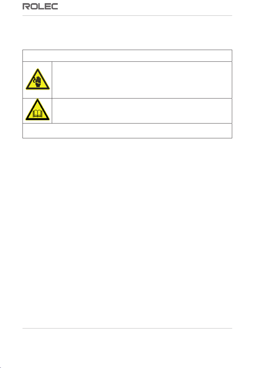
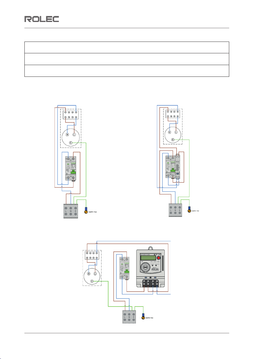
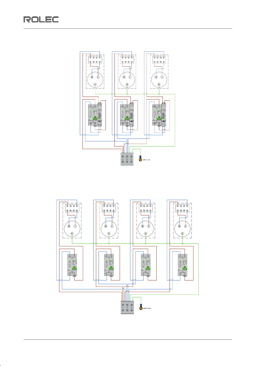
WARNING: Electrical Power (where applicable)
xInstallation of electrical systems must only be performed by an
appropriately qualified and competent electrician, in accordance
with the regulations in force in the region of installation.
xThe instructions below are illustrative only and do NOT override
anything written in the current regulations.
IMPORTANT: Installers and End Users must read and understand the content
of this manual before use.
NOTE: Damage to the equipment, connected systems or to property, caused by
improper installation or use are the responsibility of the installer and/or end user.
xThe information provided in this manual must ONLY be used with the model(s) listed
on page 1 of this manual.
xThe information provided in this manual must NOT be used with any other product.
xThe content of this manual may be updated as required.
xDo NOT use the equipment for anything other than its intended purpose.
xDo NOT modify the equipment unless specifically instructed to do so by the
manufacturer.
xDo NOT attempt to repair the equipment unless specifically instructed to do so by
the manufacturer or as detailed in this manual.
xThis product is electrically safe when in normal use.
xDamage to the product may render it unsafe. The product must be electrically
isolated and NOT used until appropriate remedial action has been performed.
Safety Advice within this Manual
Rolec manuals use a system of warnings, cautions and notes.
xWARNINGS concern the safety of installers/end user and will be given before the
detail/instructions in the manual.
xCAUTIONS concern the potential for damage to the equipment and will be given
before the detail/instructions in the manual.
xNOTES are given to provide additional information and/or highlight information of
importance. They will be given either before or after the detail/instructions as
appropriate and may use different wording (such as IMPORTANT) where emphasis is
required.
Warnings, Cautions and Notes may be repeated as appropriate and may be preceded
by a hazard symbol.

Product Overview
Outdoor Electrical Connection Units ROECUIDM-01-V01-R0 Installation and Operation Manual
June 2022 Page 4of 20
Product Overview
Rolec Caravan Hook-ups and Direct Connection Units are available in a variety of models
and power ratings.
Specifications
Input Voltage 220 to 250 VAC / 50 Hz (Single Phase)
Enclosure Material Polycarbonate (UV stabilised)
Operating Temp -25°C to +60°C
Figure 1 Small Enclosure Dimensions
NOTE: Direct Connection Units have the same enclosure dimensions as socketed Hook-
ups (minus the socket dimensions).

Product Overview
ROECUIDM-01-V01-R0 Installation and Operation Manual Outdoor Electrical Connection Units
Page 5of 20 June 2022
Figure 2 Large Enclosure Dimensions
NOTE: Direct Connection Units have the same enclosure dimensions as socketed Hook-
ups (minus the socket dimensions).

Product Overview
Outdoor Electrical Connection Units ROECUIDM-01-V01-R0 Installation and Operation Manual
June 2022 Page 6of 20
Hook-Up Units (Interlocked)
Product Code Edition - Socket Units
1 WAY
LSHU0010 1 Way 16A Hook-Up Unit
LSHU0010-10A 1 Way 16A / 10A Hook-Up Unit
LSHU0015 1 Way 32A Hook-Up Unit
LSHU0110 1 Way 16A Metered Hook-Up Unit
LSHU0110-10A 1 Way 16A / 10A Metered Hook-Up Unit
LSHU0115 1 Way 32A Metered Hook-Up Unit
LSHU0210 1 Way 16A Smartcard Metered Hook-Up Unit
LSHU0215 1 Way 32A Smartcard Metered Hook-Up Unit
2 WAY
LSHU0020 2 Way 16A Hook-Up Unit
LSHU0020-6A 2 Way 16A / 6A Hook-Up Unit
LSHU0020-10A 2 Way 16A / 10A Hook-Up Unit
LSHU0025 2 Way 32A Hook-Up Unit
LSHU0120 2 Way 16A Metered Hook-Up Unit
LSHU0120-10A 2 Way 16A / 10A Metered Hook-Up Unit
LSHU0125 2 Way 32A Metered Hook-Up Unit
3 WAY
LSHU0030 3 Way 16A Hook-Up Unit
LSHU0030-10A 3 Way 16A / 10A Hook-Up Unit
LSHU0130 3 Way 16A Metered Hook-Up Unit
LSHU0130-10A 3 Way 16A / 10A Metered Hook-Up Unit
4 WAY
LSHU0040 4 Way 16A Hook-Up Unit
LSHU0040-10A 4 Way 16A / 10A Hook-Up Unit
LSHU0045 4 Way 32A Hook-Up Unit
LSHU0140 4 Way 16A Metered Hook-Up Unit
LSHU0140-10A 4 Way 16A / 10A Metered Hook-Up Unit

Product Overview
ROECUIDM-01-V01-R0 Installation and Operation Manual Outdoor Electrical Connection Units
Page 7of 20 June 2022
Hook-up Unit Schematics (Interlocked)
NOTE: In accordance with the specific power rating of the unit, individual components
may differ to those shown. Cable routing and connections are as shown.
IMPORTANT: Installers must make sure to use the correct type of Unit in accordance with
the requirements of the location.
IMPORTANT: All Units must be earthed in accordance with the current Electrical Wiring
Regulations applicable to the site and application of use.
LSHU0010
LSHU0010-10A
LSHU0015
LSHU0110
LSHU0110-10A
LSHU0115
LSHU0210
LSHU0215

Product Overview
Outdoor Electrical Connection Units ROECUIDM-01-V01-R0 Installation and Operation Manual
June 2022 Page 8of 20
LSHU0030
LSHU0030-10A
LSHU0020
LSHU0020-6A
LSHU0020-10A
LSHU0025
LSHU0120
LSHU0120-10A
LSHU0125

Product Overview
ROECUIDM-01-V01-R0 Installation and Operation Manual Outdoor Electrical Connection Units
Page 9of 20 June 2022
LSHU0130
LSHU0130-10A
LSHU0040
LSHU0040-10A
LSHU0045

Product Overview
Outdoor Electrical Connection Units ROECUIDM-01-V01-R0 Installation and Operation Manual
June 2022 Page 10 of 20
LSHU0140
LSHU0140-10A

Product Overview
ROECUIDM-01-V01-R0 Installation and Operation Manual Outdoor Electrical Connection Units
Page 11 of 20 June 2022
Direct Connection Units
Product Code Direct Connection Units
kWh Metered
LSDC0110 1 x 16A 230V Metered Direct Connection Unit
LSDC0120 1 x 32A 230V Metered Direct Connection Unit
LSDC0130 1 x 63A 230V Metered Direct Connection Unit
LSDC0210 1 x 16A 230V Smartcard Metered Direct Connection Unit
LSDC0220 1 x 32A 230V Smartcard Metered Direct Connection Unit
LSDC0230 1 x 63A 230V Smartcard Metered Direct Connection Unit
Direct Connection Unit Schematics
NOTE: In accordance with the specific power rating of the unit, individual components
may differ to those shown. Cable routing and connections are as shown.
IMPORTANT: Installers must make sure to use the correct type of Unit in accordance with
the requirements of the location.
IMPORTANT: All Units must be earthed in accordance with the current Electrical Wiring
Regulations applicable to the site and application of use.
LSDC0110
LSDC0120
LSDC0130

Product Overview
Outdoor Electrical Connection Units ROECUIDM-01-V01-R0 Installation and Operation Manual
June 2022 Page 12 of 20
LSDC0210
LSDC0220
LSDC0230
Certifications and Compliances
This product has been designed and built in accordance with the following standards and
legislation:
Enclosure EN 60670-1, EN 60670-22
Wiring Regulations 18th Edition BS7671:2018+A1:2020 (where applicable)
Flame Retardance IEC 60695-2-11:2014
Low Voltage (LVD) The Low Voltage Directive (2014/35/EU)
The Electrical Equipment (Safety) Regulations 2016
(SI 2016/1101)
Environmental Protection IP65 Enclosure, IP44 Socket(s)
Weather resistance BS EN 60529:1992+A2:2013
Socket(s) – Where fitted BS EN 60309-2:1999+A2:2012
Cable – Where fitted BS 6004
Metering – Where fitted EN50470-1, EN50470-3,
MID B+D Certified
The Measuring Instruments Directive (2014/32/EU)
The Measuring Instruments Regulations 2016 (SI 2016/1153)
RoHS Restriction of the Use of Certain Hazardous Substances in
Electrical and Electronic Equipment Regulations (2002/95/EC)
(SI 2012/3032)
REACH 1907/2006

Labelling
ROECUIDM-01-V01-R0 Installation and Operation Manual Outdoor Electrical Connection Units
Page 13 of 20 June 2022
Labelling
Users must observe the information given on labels to ensure safe use of the product.
Labels may be in the form of adhesive ‘stickers’, plates, and/or moulded into the surface
of components.
Figure 3 Typical Product Label(s)
Figure 4 Typical Smartcard Meter Label
NOTE: Labels may vary depending on the model. Always refer to the label attached to
the unit.
Plugs and Couplers are labelled with their specific IP rating and power rating.
Warning: Electrical Hazard
xDo NOT exceed the power rating displayed on the label(s).
xDo NOT change the plug/coupler to accept a connection to a higher rated
power source.
xDo NOT use cables that are not sufficiently rated for the power they will be
required to carry.
Internal components are labelled with their power rating (as appropriate) by the
component manufacturer.
Warning: Electrical Hazard
xAlways use the originally installed component as a reference – model numbers
and electrical ratings may differ to those shown in the schematics section of this
manual.
xDo NOT change components to models with different power ratings or different
operational characteristics. The safety and correct operation of the unit may be
affected.

Installation
Outdoor Electrical Connection Units ROECUIDM-01-V01-R0 Installation and Operation Manual
June 2022 Page 14 of 20
Installation
Before Installation
WARNING: Electrical Power
xInstallation of this equipment must only be performed by an
appropriately qualified and competent electrician, in accordance
with the regulations in force in the region of installation.
xThe instructions below are illustrative only and do NOT override
anything written in the current regulations.
IMPORTANT: Installers and End Users must read and understand the content
of this manual before use.
IMPORTANT: Installers must make sure to use the correct type of Unit in
accordance with the Electrical Wiring Regulations of the geographical
location.
NOTE: Damage to the equipment, connected systems or to property, caused by
improper installation or use are the responsibility of the installer and/or end user.
Install the Unit
1. Make sure the installation is performed in accordance with the current Electrical
Wiring Regulations.
2. Identify a suitable and safe location for the Unit to installed.
xThe unit is designed to be wall or post mounted in an upright position.
xIf installing a mounting post, take care not to damage any underground
services when the post is installed.
3. Refer to the appropriate schematic for the Unit being installed.
4. Make sure the incoming power supply cable is disconnected from electrical power.
5. Take the Unit from its packaging and remove the unit lid (front cover).
6. Create a suitably sized hole(s) in the bottom of the unit to accept the incoming
power supply cable(s).
xTake care not to damage any of the internal components.
xMake sure all drilling debris is removed from the enclosure and the internal
components.
If a mounting post is supplied:
7. Make sure the post and Unit will fit together correctly.
8. Fix the mounting post in the desired location.
9. Offer up the rear enclosure to the post and make sure the holes in the post
align with the holes in the enclosure. If required, drill out the holes in the
mounting post to ensure smooth fitment of fasteners.
10. Secure the rear enclosure onto the post using the supplied fasteners.

Installation
ROECUIDM-01-V01-R0 Installation and Operation Manual Outdoor Electrical Connection Units
Page 15 of 20 June 2022
If a mounting post is not supplied:
11. Carefully place the rear enclosure of the Unit in the desired location and
mark the four fixing points. Remove the enclosure before drilling.
WARNING: Equipment Damage
Do NOT use the enclosure as a drilling guide. Debris from drilling can
damage internal components. Mark the drilling points then remove the
enclosure before drilling.
12. Drill the mounting location as appropriate to receive the fasteners.
13. Use suitable fasteners, to mount the rear enclosure in the required location.
14. Feed the power supply cable up through the hole in the rear enclosure. Use a
suitably sized cable gland to ensure a water-resistant seal.
15. Terminate the supply cable in the appropriate manner and connect to the Unit
terminals.
16. Make sure any debris is removed from the enclosure.
17. Replace the unit lid ensuring it sits correctly on the enclosure then tighten the
fasteners securely to provide the correct weatherproof sealing.
18. Make sure it is safe to apply electrical power to the Unit.
19. Apply electrical power to the Unit and, if applicable, switch the Unit’s circuit
breaker to the ON position.
20. Test the Unit and the electricity supply from the Unit in accordance with current
Electrical Wiring Regulations.
Security
When installation of the Unit is complete, the clear hatch (if fitted) should be secured with
a suitable padlock to prevent access and to prevent the entry of dust and/or water to the
enclosure.
Some units also feature lockable socket covers and/or lockable rotary power switches
allowing a small padlock to be used to prevent tampering and uncontrolled use of
electricity.

Operation
Outdoor Electrical Connection Units ROECUIDM-01-V01-R0 Installation and Operation Manual
June 2022 Page 16 of 20
Operation
Warning: Electrical Hazard
xDo NOT exceed the power rating displayed on the label.
xDo NOT change the cable plug/coupler to accept a connection to a higher
rated power source.
xDo NOT extend cables without taking advice from a qualified electrician.
xDo NOT place strain on the connection(s) or stretch the cable.
xMake sure the cable is fully uncoiled before use. Coiled power cables can
generate heat and electrical fields.
xDo NOT use damaged cables or connectors.
xDo NOT use contaminated cables or connectors.
xWhen in use, make sure cables do not present an obstruction or trip hazard.
xAfter use, store removeable cables in a clean, dry and secure environment.
Socket Units
Connect a Power Connection Cable to an Interlocked Hook-Up Unit
1. Fully uncoil the cable.
2. Make sure the plug, coupler, cable and Hook-Up Unit appear to be in an
undamaged, serviceable condition.
3. Make sure the cable is securely connected to the caravan (or appliance) socket.
4. Make sure the rotary power switch on the Hook-Up Unit is in the OFF position.
xIt should not be possible to turn the switch without a cable connected.
xIf the switch is in the wrong position, there may be damage to the
switch/connection. Do not use the connection until repairs have been
made.
5. Insert the plug of the Hook-Up cable into the Hook-Up socket.
6. Make sure the circuit breaker is in the
ON position.
7. Turn the rotary power switch to the
ON position.
Power should now be available.
Figure 5 Rotary Power Switch Positions
NOTE: Rotary power switches can be locked to prevent use when in the Power OFF
position. Apertures in the outer ring of the switch (at the 2 o’clock and 7 o’clock
positions) allows a padlock or similar device to be used to prevent the switch being
turned to the ON position.

Operation
ROECUIDM-01-V01-R0 Installation and Operation Manual Outdoor Electrical Connection Units
Page 17 of 20 June 2022
Disconnect the Power Connection Cable from an Interlocked Hook-Up Unit
1. Make sure the rotary power switch is turned to the OFF position.
2. Pull the Hook-Up cable from the Hook-Up unit.
3. Make sure the socket cover is closed when not connected to a cable.
4. Remove the cable from the caravan (or appliance) socket.
5. Loosely coil the power cable ready for next use and store in a clean, dry and
secure environment.
Direct Connection Units
Direct Connection Units do NOT have a rotary power switch and, as standard, are not
supplied with a connection cable or connector plug.
Direct Connection Units are intended to be wired directly to the building (or
appliance)and electrical power coming from the Unit is permanently live unless
interrupted by the RCBO or power is stopped at source before being fed to the Unit.

Unit Maintenance
Outdoor Electrical Connection Units ROECUIDM-01-V01-R0 Installation and Operation Manual
June 2022 Page 18 of 20
Unit Maintenance
WARNING:
xElectrical maintenance of this product must only be performed by
an appropriately qualified and competent person, in accordance
with the regulations in force in the region of installation.
xReplacement sockets/couplers must be of the same type and rating
as the original items. Do NOT exceed the power rating of the original
fittings.
1. Regularly clean the external surfaces of the equipment with a damp cloth.
CAUTION: Equipment Damage
To avoid damage to the surface finish, and/or internal components do NOT use:
xAbrasive materials.
xMineral or petroleum solvents / degreasers.
xHose pipes.
xJet washers.
xSteam cleaners.
2. Regularly inspect the exterior of the equipment for visual damage.
xIf damage affects safety, isolate the equipment and prevent its use until
appropriate repairs have been completed.
3. Make sure the enclosure fasteners are secure and that the enclosure is fully closed.
4. Make sure the enclosure is secure on its mounting location.
5. Make sure the power cable entering the enclosure is in good condition and that it is
securely attached to the enclosure.
6. Make sure the clear flap (if installed) is in good condition, moves smoothly, can be
closed securely, and that a weather resistant seal is made.
7. Make sure socket covers (if installed) are present and can close securely when a
cable is not in use.
8. Make sure electrical cables are secure and are in a serviceable condition.

Unit Maintenance
ROECUIDM-01-V01-R0 Installation and Operation Manual Outdoor Electrical Connection Units
Page 19 of 20 June 2022
RCBOs
A ‘Residual Current Breaker with Over-Current’ (RCBO) is an electrical fault, safety device
that combines the functions of a miniature circuit breaker (MCB) and a residual current
device (RCD). Operation by the end user is virtually identical for all these devices.
Each Rolec Hook-Up Unit is equipped with an RCBO of the appropriate rating which will
cut power to the Hook-Up socket(s) or cable in the event of:
xEarth Leak – Where a physical break or damage to the electrical circuit is detected
being fed to Earth. Often when someone accidentally cuts into a cable.
xOvercurrent – Where too much power is being drawn through the unit.
xShort Circuit – Where there is a direct connection between live and neutral
conductors.
If the RCBO is activated (tripped), the lever on the front of the device will point
downwards. The RCBO may be reset when the issue is resolved.
To reset the RCBO, simply move the lever to the upwards position.
IMPORTANT: If the RCBO trips regularly or cannot be reset, the issue should be
investigated by and appropriately qualified electrician.
Power Consumption Meters
If installed, meters installed in Caravan Hook-up and Direct Connections Units comply with
the Measuring Instruments Directive - 2014/32/EU.
xThe meter reading window is located next to the RCBO. If power to the meter is lost,
the meter display will go blank but the reading will not be lost and will be displayed
again when power is restored.
If a Smartcard meter is installed, operating instructions for the meter are shown on a label
attached to the unit.
This manual suits for next models
29
Table of contents
Other ROLEC Automobile Accessories manuals
Popular Automobile Accessories manuals by other brands

Edscha Trailer Systems
Edscha Trailer Systems CS-LitePlus quick guide

Toyota
Toyota VSS4 owner's manual

BORLA
BORLA 60087 installation instructions

DoubleTake
DoubleTake SeatBack Plates installation instructions

Lund
Lund Interceptor Installation instruction

EOinnovations
EOinnovations EOC3103 instruction manual

Rugged Ridge
Rugged Ridge 13579.71 installation instructions

Quadratec
Quadratec 11147.10 Series installation manual

Magneti Marelli
Magneti Marelli OZON MAKER user manual

Mont Blanc
Mont Blanc FK161 Fitting instructions

TEINHOF
TEINHOF C-270 FITTING AND OPERATION MANUAL

Flash Cover
Flash Cover MN012 installation manual