Palfinger MBB C 500 VAN User manual

Assembly Instruction
MBB C 500 VAN / MBB C 500 VAN FLEX
Larisch 13-513_99-04_00-03 A23676, 06/06/19
PALFINGER Tail Lifts GmbH | Fockestraße 53 | D-27777 Ganderkesee | T + 49 4221 853-0 | infombb@palfinger.com | www.palfinger.com
Types per:
96-522.99
1. Please check before assembly
1. Does the delivery correspond with your order?
2. Is the appropriate assembly drawing for type C 500 VAN available?
3. Does the operating voltage of the C 500 VAN correspond to that of the vehicle?
4. Do you intend to install a false floor (raised wear floor)?
5. Check the supporting strap (25 mm of free space available between platform and strap).
6. Always adhere to the vehicle manufacturer's assembly instructions.
PREPARATORY WORK ON THE VEHICLE
Remove any spare wheels and their retainers that may be mounted under the vehicle tail. Dismount
any towing coupling, towing hook or climbing aids that may be present at the vehicle tail. Replace
special bumpers having integrated climbing aids with standard bumpers.
Remove the vehicle license plate from the rear doors and re-attach it in a location that will be visible
after assembly of the MBB C 500 VAN (observe the national regulations pertaining to the license
plate location).
Install the delivered link bridge in the vehicle. Place the link bridge directly behind the vehicle's
closed rear doors. If required, adapt the link bridge width. Fasten the link bridge to the vehicle floor
using the delivered screws.
PREPARATORY WORK ON THE VEHICLE CHASSIS (VEHICLES WITH HOLLOW SECTION
CHASSIS)
The C 500 VAN is delivered with vehicle-specific consoles and has to be assembled using the
enclosed assembly kit. Use any existing base on the vehicle chassis (e.g. towing coupling retainer)
for fastening. Drill additional holes in the vehicle chassis frame in the locations where fastening
points are provided in the console. Weld the corresponding tubes of the enclosed assembly kit into
the van's hollow section chassis in flush position on both sides. When drilling, make sure that the
console is assembled in parallel with the vehicle's main chassis beams. The tubes are used to
prevent deformation of the hollow section chassis.
PREPARATORY WORK ON THE VEHICLE CHASSIS (VEHICLES WITH CHANNEL SECTION
CHASSIS)
The C 500 VAN is delivered with vehicle-specific consoles and has to be assembled using the
enclosed assembly kit. Use any existing base on the vehicle chassis (e.g. towing coupling retainer)
for fastening. Drill additional holes in the locations where fastening points are provided in the
console.
NOTE
Special tools like coil testers, pressure gauges, etc. are available from PALFINGER Tail Lifts on
request.
2. Assembling the lifting platform
1. Assemble the vehicle-specific consoles using the enclosed assembly kit.
2. Lift the pre-assembled lifting device under the vehicle using the appropriate hoist and use the delivered
hexagon head screws M 14 (6 pieces) to screw it to the consoles.
When doing so, mount the screws from inside to outside. On the tilt cylinder side, initially fit 2 screws
with the tilt cylinder retracted. Fit the third screw with the tilt cylinder extended.
CAUTION! The lifting device may swivel down as there is not yet enough oil in the lift cylinder.
4. Lift the torsion frame using the appropriate hoist until reaching the loading floor level with lift arm
contour.
CAUTION! Be aware of interfering contours while lifting
5. Adjust and fix the height stops of the lifting device at the support tube. Important: Make sure that both
height stops are at the same level.
Otherwise, the lifting device may be damaged (see illustration on right side).
6. Then bolt the platform to the lift arms. The platform is to be installed vertically behind the vehicle.
Secure the pin with the tabs using the M12 screw provided and tighten to a torque of 75Nm.
Hydraulic unit Height stops Support tube Lift cylinder Torsion frame
Tilt cylinder Drawbar
C 500 VAN
C 500 VAN FLEX
Pin
Locking screw
Tab
Pin

Larisch 13-513_99-04_00-03 A23676, 06/06/19
PALFINGER Tail Lifts GmbH | Fockestraße 53 | D-27777 Ganderkesee | T + 49 4221 853-0 | info[email protected]m | www.palfinger.com
3. Installation of electrics
1. Refer to the corresponding C 500 VAN circuit diagram (see the Operating Instruction Manual
provided) and follow the vehicle manufacturer's assembly instructions.
2. Run the battery cable to the battery, shorten it if required and install the cable lug
3. Assemble the main fuse with the cable lug and connect it to the battery positive terminal.
4. Lay the controller cable through to the driver's cab. In the driver's cab, select the appropriate place
at the instrument panel, establish an electrical connection according to the C 500 VAN circuit
diagram and attach the control box.
5. If a control box already exists in the vehicle, connect the C 500 VAN according to the additional
circuit diagram. If necessary, order this circuit diagram from PALFINGER Tail Lifts.
6. Establish a ground connection according to the vehicle manufacturer's assembly instructions
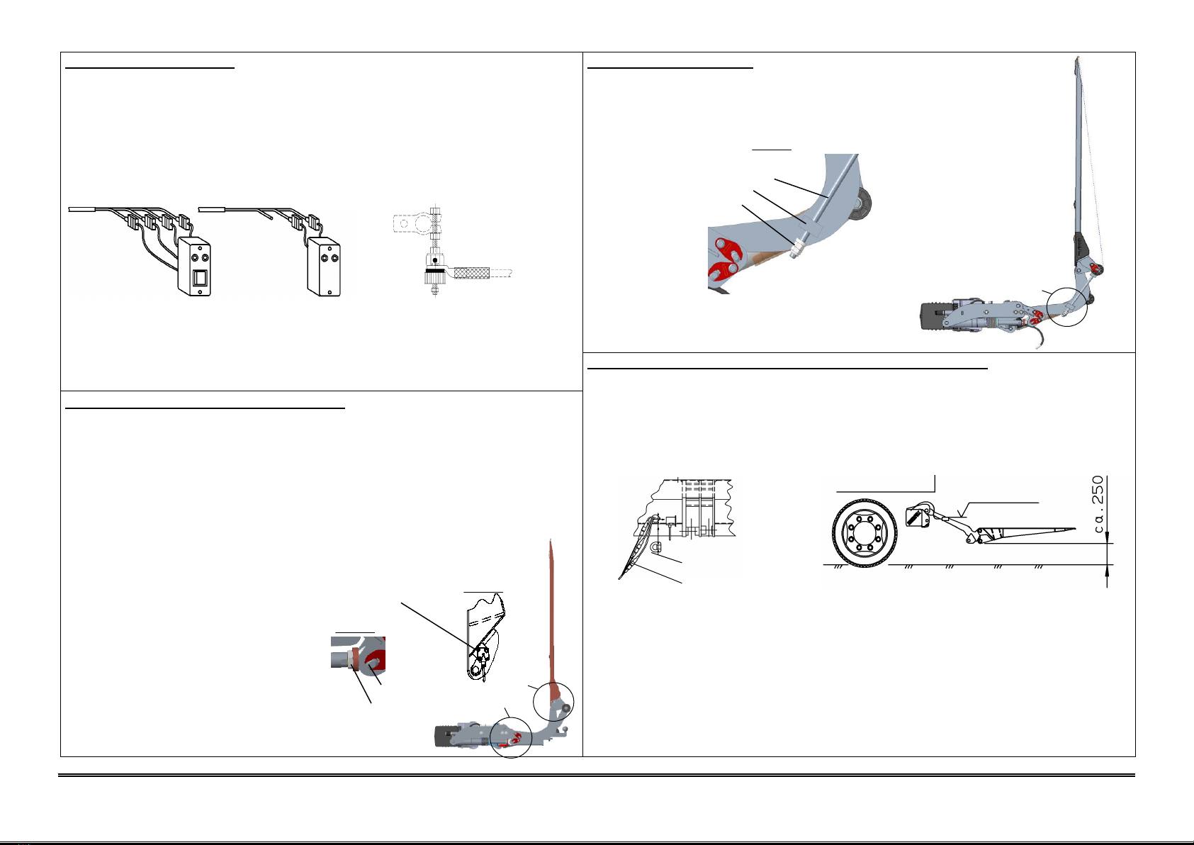
Control unit for Control unit for
motor vehicle semitrailer and trailer
7. CAUTION! For DGRTR vehicles, connect the ground cable to the battery or according to the vehicle
manufacturer's assembly instructions.
8. The hand cable control may be operated from the marked position on the platform, only.
4. Assembly and adjustment - tilt cylinder
1. Turn the tilt cylinder's rod head until reaching the piston rod stop. Actuate the Open or Close control
switch to set the tilt cylinder to a length that allows you to bolt the cylinder to the platform. For this
purpose, hold down the tilt sensor b15/b16 with the cable. Pin platform with the tilt cylinder, secure
with the tab and secure with M12 screw. Tighten this to a torque of 75Nm.
2. Move the lifting device up to the height stop using the lifting cylinder. If required, remove the
auxiliary unit.
3. Attach the tilt sensor b15/b16, as seen in the diagram, to the dedicated platform strap on the right-
hand side so that the potting compound is oriented towards the outside.
4. Unscrew the drawbar nuts as far as possible.
5. Close the platform towards the vehicle body as far as possible (fully extend the tilt cylinder),
release the tilt cylinder by briefly actuating the "Open" pushbutton switch
and turn the piston rod
using an open ended wrench to close the
platform as far as possible until it is approx.
5cm from the vehicle body (doors).
NOTE! In this platform position
the tilt cylinder must be fully extended
to the stop.
CAUTION! The platform must not come in
contact with the vehicle body, which
may otherwise be damaged.
6. De-pressurise the tilt cylinder by opening the platform
and fasten the piston rod counter nut according
to the assembly drawing.
5. Adjusting the drawbar
1. Lift the platform up fully to the top.
2. Close the platform to the desired vertical position.
3. Turn the nut and counter nut to the stop and tighten to approx. 50Nm.
4. Tighten the counter nut.
Drawbar
Stop
Nut/counter nut
6. Adjustment and installation work prior to commissioning
1. Loosen the strain relief (plastic cap at the platform head profile). Pull the cable with the connector plug
for the foot control and Warnfix out of the platform (make sure that the cable length is sufficient) and then
reinstall the strain relief. Run the cable along the hydraulic hoses to the hydraulic unit. Use cable binders.
Connect the plug to the appropriate receptacle on the PCB according to the circuit diagram. Insert the
cable through the entry into the hydraulic unit housing and position the protection sleeve. Close the
hydraulic unit.
2. Close the platform to the body.
3. All cables installed must be carefully laid and securely fastened. Sufficient bending lengths must be
observed.
4. Lower the platform until reaching a level of approx. 250 mm above ground and set the switch b13 at the
torsion frame to its horizontal position. For this purpose, undo the switch fastening screw, re-tighten it
after the setup and fold back the locking plate.
5. Lift, lower, open and close the platform several times in order to bleed the cylinder. If required, adjust the
platform's horizontal position on the ground by turning the tilt sensor b16 accordingly.
6. Check the oil level with lowered platform and check that all screw connections established according to
the assembly drawing are tight. Perform an acceptance test according to the test data booklet and record
the test results in the test data booklet.
Main fuse
Strain relief
Switch b13
horizontal
Connector for foot
control and Warnfix
Counter nut
Rod head
Detail Z
Tilt sensor b15/b16
Z
X
Detail X
X
Detail X
This manual suits for next models
1
Other Palfinger Automobile Accessories manuals
Popular Automobile Accessories manuals by other brands

DK2
DK2 BCR290 installation manual

Roadmaster
Roadmaster BrakeMaster 9000 installation instructions

Rear view safety
Rear view safety RVS-770613-213 installation instructions

Auto Styling
Auto Styling Truckman GLS Fitting instructions

Unitec
Unitec LT 102063 Instructions for use

Whispbar
Whispbar K836W Fitting instructions