EGR RollTrac User manual
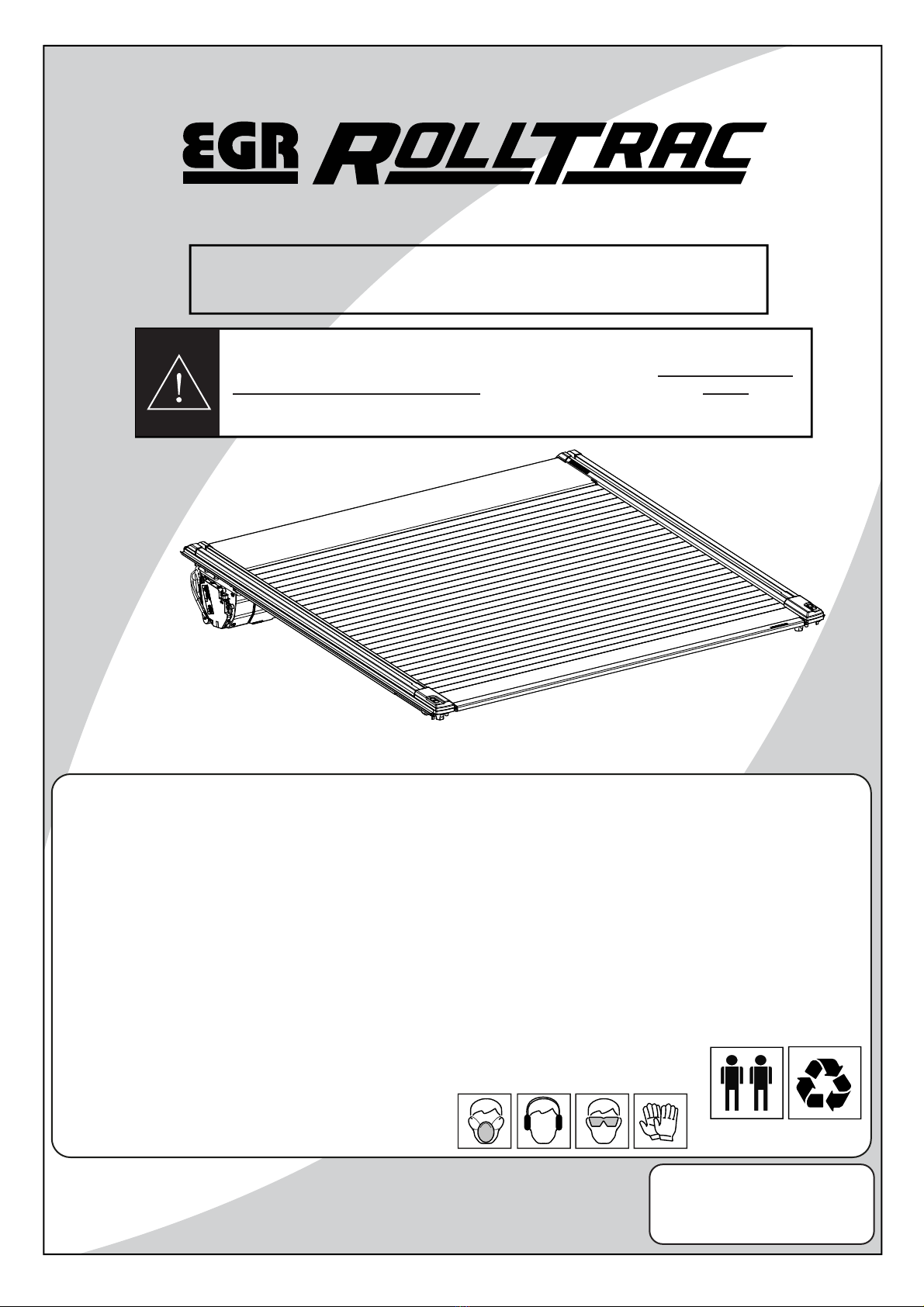
RT0063
Page 1 of 33
ISSUE 4: 26/04/23
Installation time: 180 minutes (without tubliner)
INSTALLATION INSTRUCTIONS
ELECTRIC
• Check that all work practices comply with safety standards.
• Please wear appropriate clothing and use safety equipment.
Caution
Safety Notes
• Do not attach EGR RollTrac in a location or by a method not specified.
• Do not use this product for any vehicle make or model, other than those specified in this document.
• Do not remove the plaque or label from this product.
• Do not modify the structure of the EGR RollTrac in any way.
• Read through the fitting instructions before installation of EGR RollTrac.
• Always install the accessory following the fitting instructions. Failure to do so may cause damage to the vehicle or the accessory.
• Ensure all recyclable discarded vehicle accessory components and packaging are recycled following local recycling regulations.
• It is always recommended that this accessory is fitted by a qualified Technician.
• Safely store and protect any removed vehicle components.
• Ensure all bare metal surfaces are protected using Automotive Bare Metal Primer and touch-up paint.
• Remove all metal swarf and dust from all vehicle surfaces if surface is used for accessory installation.
General Notes
Vehicle Model: FORD RANGER
Year of manufacture: MY22 onwards
*RT0063*
IMPORTANT:
IF THE EGR ROLLTRAC IS FITTED TO THE VEHICLE WITH ANY ACCESSORY
LOADED WITH MORE THAN 45KG, A TUB REINFORCEMENT KIT MUST BE
FITTED. THE TUB REINFORCEMENT KIT CAN BE PURCHASED FROM YOUR
LOCAL FORD DEALER OR DIRECTLY FROM EGR (PART No. KIT040256).
-- EGR Document ID#121541 v5 2023-05-09 23:59:32 awilmott --
RT0063
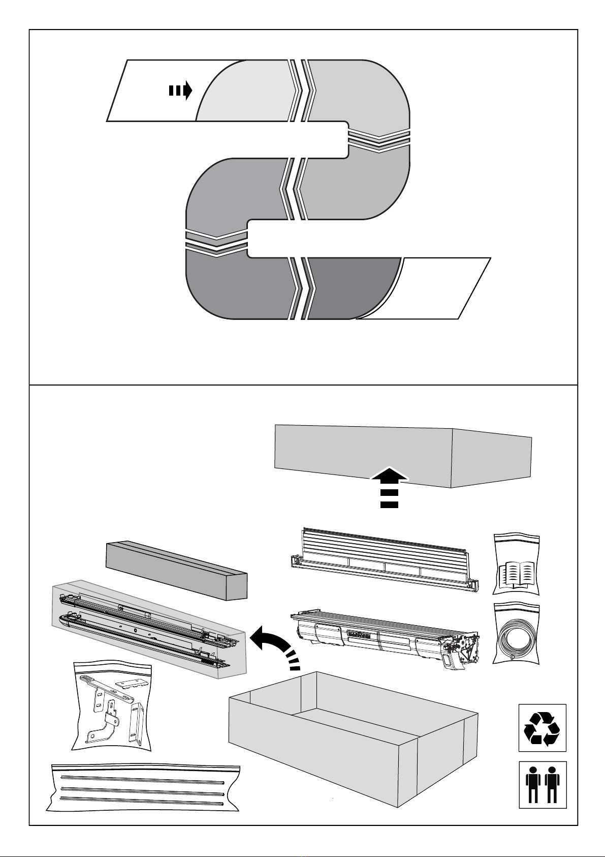
TUB PREP
SECTION B
STEP 1-14
ELECTRICAL
SECTION A
STEP 1-8
EGR ROLLTRAC
ASSEMBLY
SECTION C
STEP 1-11
CALIBRATION
SECTION E
OPERATIONS
FINAL NOTES
FINISH
EGR ROLLTRAC
INSTALLATION
SECTION D
STEP 1-8
Page 2 of 33ISSUE 4: 26/04/23
FINISH
START
INSTALLATION PROCESS
UNPACKING
FITTING KIT
-- EGR Document ID#121541 v5 2023-05-09 23:59:32 awilmott --
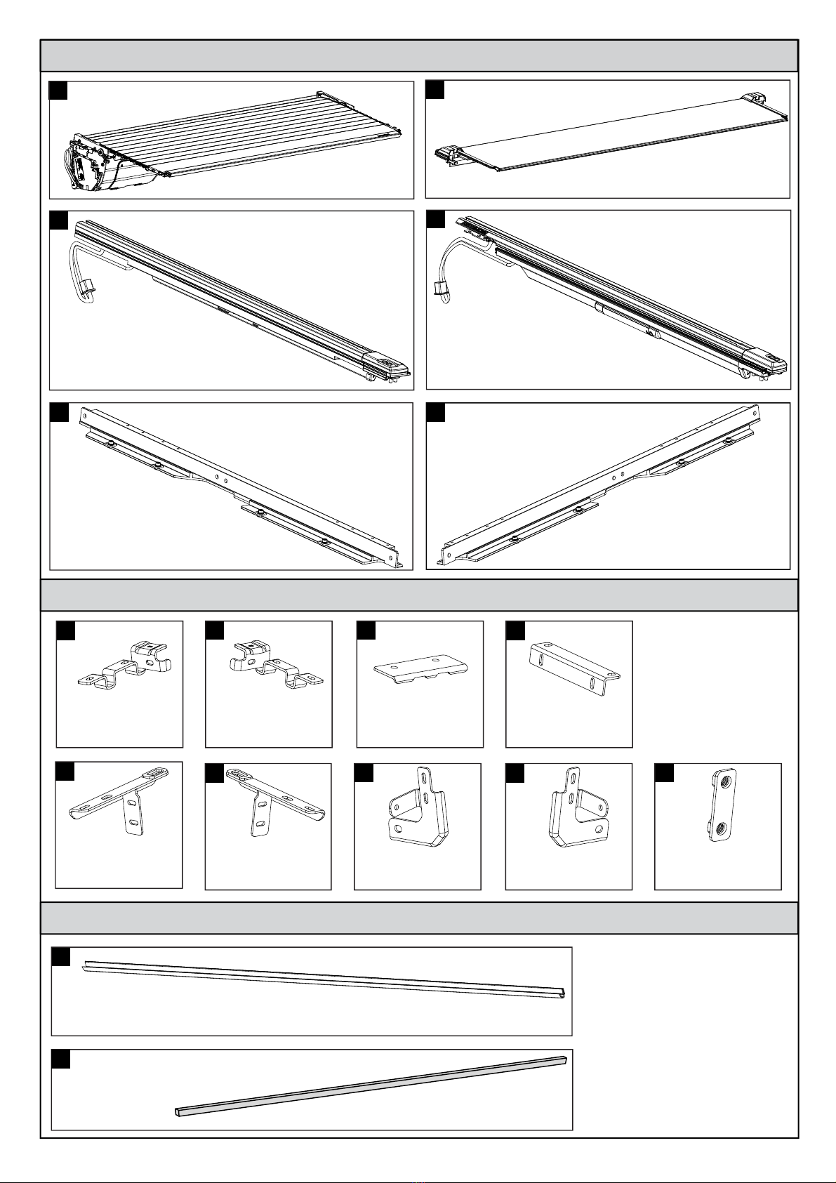
KIT CONTENTS - COMPONENT NUMBER AND QUANTITY
LHS RAIL QTY: 1
FR MNT BRK
CLIP3932PC-LH
QTY: 1
MNT BAR
TGAT0032-LH
QTY: 1
MNT BAR
TGAT0032-RH
QTY: 1
FR MNT BRK
CLIP3932PC-RH
QTY: 1
H-BAR CRN BRK
CLIP4106
QTY: 2
MNT BRK
CLIP4108
QTY: 4
REAR SUPP BRK
CLIP4110-LH
QTY: 1
REAR SUPP BRK
CLIP4110-RH
QTY: 1
REAR MNT BRK
CLIP4109-LH
QTY: 1
REAR MNT BRK
CLIP4109-RH
QTY: 1
M6 NUT PLATE
MISC5793
QTY: 2
RHS RAIL QTY: 1
FRONT COVER QTY: 1
CANISTER ASM. QTY: 1
12
34
56
789
11 12 13 14 15
16
10
EGR EGR ROLLTRAC CLAMP KIT IN BAG
EGR EGR ROLLTRAC BULB KIT IN BAG
RT0063
Page 3 of 33ISSUE 4: 26/04/23
17
SIDE RAIL SEAL
EXTR0112-32
QTY: 2
FRONT RAIL SEAL
TAPE0752
QTY: 1
-- EGR Document ID#121541 v5 2023-05-09 23:59:32 awilmott --
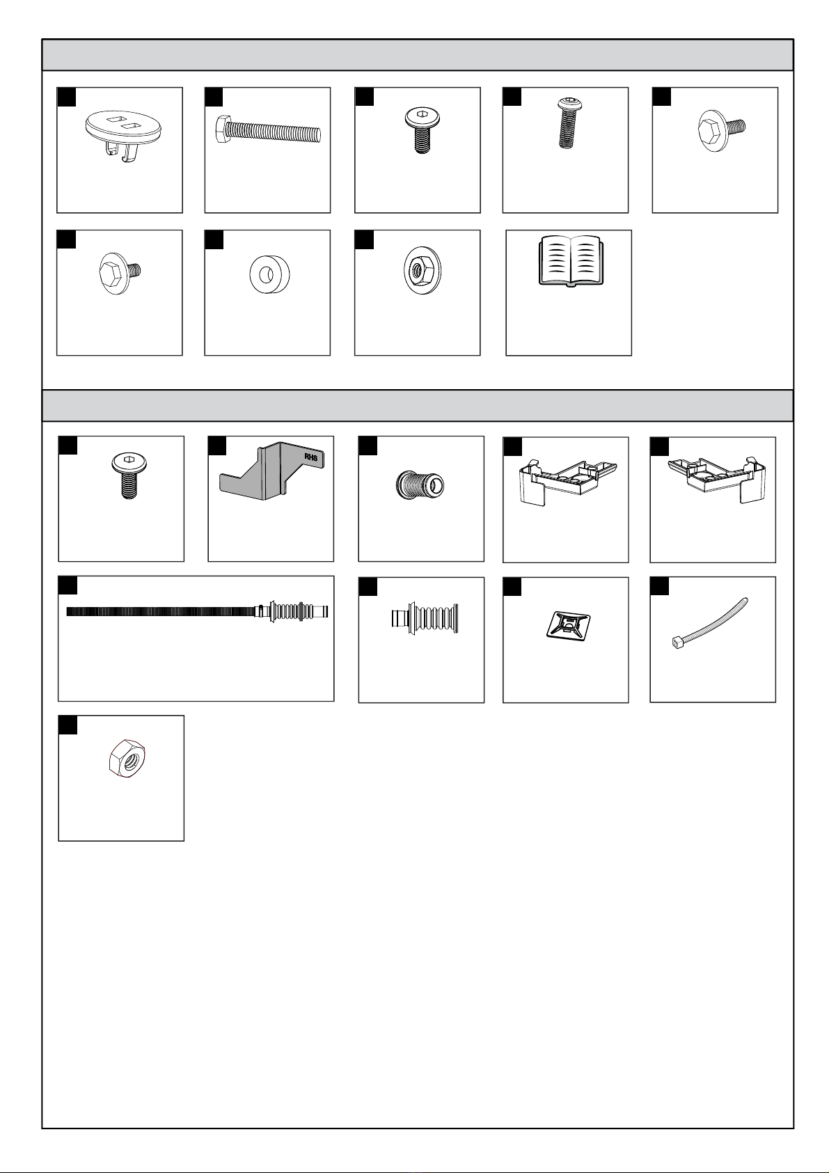
SCREW END PAD
MISC5812
QTY: 8
M6x50 HEX HEAD
SCRW0967
QTY: 8
M6x20 HEX HEAD
SCRW0997
QTY: 10
M6x15 HEX DRIVE
SCRW0973
QTY: 14
M6x15 HEX DRIVE
SCRW0973
QTY: 6
M8x25 BUTTON HEAD
HEX DRIVE
SCRW0974
QTY: 6
EGR EGR ROLLTRAC MBAR HARDWARE KIT IN BAG
EGR EGR ROLLTRAC FITTING KIT IN BOX
INSTALLATION
INSTRUCTIONS
&
OWNERS MANUAL
RT0063
Page 4 of 33
ISSUE 4: 26/04/23
18 19 20 21
M6x15 HEX HEAD
SCRW01001
QTY: 16
SPACER
MISC5457
QTY: 6
WATER DUCT
INJM0274-RH
QTY: 1
REAR DRAIN TUBE
(VEHICLES WITHOUT DDK ONLY)
QTY: 2
M6 HEX NUT
NUTS0285
QTY: 8
M6 HEX NUT
NUTS0284
QTY: 2
FIT JIG
MISC5822
QTY: 1
22
23 24 25
26 27
FR DRAIN TUBE
MISC5222
QTY: 2
28 30
31
REAR DRAIN TUBE
(DDK ONLY)
MISC5223-32
QTY: 2
32
CABLE TIE BASE
MISC5128
QTY: 2
33
WATER DUCT
INJM0274-LH
QTY: 1
29
CONS70097
CABLE TIE
QTY: 8
34
35
-- EGR Document ID#121541 v5 2023-05-09 23:59:32 awilmott --
PARTS IN VEHICLE HARNESS
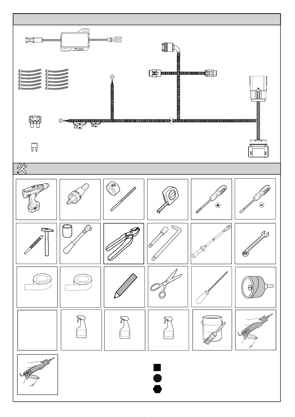
TOOLS REQUIRED - NOT SUPPLIED IN KIT
Page 5 of 33ISSUE 4: 26/04/23 RT0063
ANTI RUST
Torque Wrench
50/50
Isopropyl Alcohol/Water Soapy Water
Silicone Spray
Silicone
Silicone
(non-acidic)
Rust Inhibitor
Flat Screwdriver
Spanners 8,10,13mm
Allen Key 2.5 & 4mm
Ratchet & Sockets
7,10,13mm
Phillips Screwdriver
Drill Tape Measure
Scissors
Masking Tape
Fiberglass Tape
Black Cloth Tape
Anti-abresion tape to seal
holes & slots Non-permanent pen
Drill Bits
Bobbin Sander Ø60mm
Ø60mm
Ø38mm
Ø29mm
Drill Stop
Centre Punch & Hummer
Holesaw
Side Cutters
Cutting device
needed to trim
bed cap
6mm File
1
1
1
GLOSSARY:
Number inside a square indicate part number
Number inside circle indicate the sequence within a step
Number inside the hexagon indicate torque instruction
SPP UNIT
VEHICLE HARNESS
CABLE TIE
QTY: 12
MINI FUSE
25A FUSE
-- EGR Document ID#121541 v5 2023-05-09 23:59:32 awilmott --

RT0063
SECTION - A ELECTRICAL SECTION
Page 6 of 33ISSUE 4: 26/04/23
A
C
DEF
G
H
I
B
AB
CD
FG
E
STEP 1
STEP 2
STEP 5,6
STEP 7
STEP 4
STEP 3
IMPORTANT: DISCONNECT CAR BATTERY NEGATIVE TERMINAL.
FIT THE SUPPLIED FUSES AT THE END OF INSTALLATION.
-- EGR Document ID#121541 v5 2023-05-09 23:59:32 awilmott --

RT0063
Page 7 of 33ISSUE 4: 26/04/23
IMPORTANT: Make sure the fuses are not fitted before making connection.
Connect the vehicle harness branch (B) to vehicle body negative ground as shown and secure with M6 hex nut (35).
Connect the vehicle harness branch (A) to the positive terminal of the battery and secure with M6 hex nut (35).
Once it is positioned, secure in place using two cable ties as shown.
Pull the vehicle harness from engine bay down to the floor behind the front left wheel. Direct it towards the rear of
the vehicle. Secure the vehicle harness to the vehicle loom in the two areas shown using cable ties.
A
A
B
B
BATTERY
POSITIVE TERMINAL
NEGATIVE TERMINAL
A
B
REAR
1
2
35
35
-- EGR Document ID#121541 v5 2023-05-09 23:59:32 awilmott --
RT0063
Page 8 of 33ISSUE 4: 26/04/23
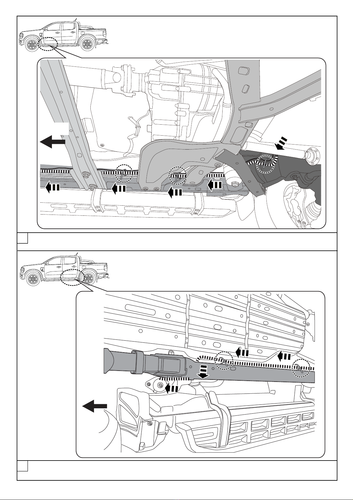
Continue running the vehicle harness along the chassis rail inner side. Feed the harness to the outside of the
chassis rail (over the top of the rail) at the rear wheel arch as shown. Secure with two cable ties as shown.
Continue to the rear along the chassis rail inner side (above the crossmembers). Secure the vehicle harness to
the existing vehicle harness as shown using cable ties.
REAR
REAR
4
3
-- EGR Document ID#121541 v5 2023-05-09 23:59:32 awilmott --

RT0063
Page 9 of 33
ISSUE 4: 26/04/23
CD
E
CD
E
H
I
Push a draw wire down through the opening in the front LHS of the tub. Under the tub, wrap the vehicle harness
connectors: C, D & E to the draw wire as shown. Pull them up into the tub until approximately 300mm protrudes.
Remove tape and draw wire from the harness.
DRAW
WIRE
TAPE
VEHICLE
HARNESS
DRAW WIRE
VIEW INSIDE TUB
VIEW INSIDE TUB
REAR
C
D
E
5
6
Connect the SPP unit to the vehicle harness as shown. Secure SPP unit and connectors to underside of tub
flange using cable ties and cable tie base x2.
SPP UNIT
TUB
-- EGR Document ID#121541 v5 2023-05-09 23:59:32 awilmott --

RT0063
Page 10 of 33ISSUE 4: 26/04/23
F G
Run the vehicle harness along the inner chassis rail aide and along the tail end of the vehicle till reaching the
loom connectors on as shown. Using cable ties, secure the vehicle harness to the vehicle tub in 4 locations as
shown . Disconnect the 16 pin vehicle loom connectors and patch it using the vehicle harness connectors F& G.
VEHICLE HARNESS
VEHICLE LOOM VEHICLE LOOM
RHS
REAR
REAR
Push the remaining harness over to the chassis rail inner and continue running it towards the rear of the vehicle.
Secure with 3 Cable Ties as shown.
REAR
7
8
-- EGR Document ID#121541 v5 2023-05-09 23:59:32 awilmott --

RT0063
SECTION - B TUB PREPARATION
Page 11 of 33ISSUE 4: 26/04/23
1
2
If CMS rail is present, remove and retain CMS rail, hex head screws (A) and torx screw (B). If CMS rail is not pres-
ent, remove torx screw (B) located at the rear of the tub. Retain the CMS bar and hardware for refit.
If Sportsbar is present, remove it and store in safe place. Keep brackets attached to the tub. Clean the top and inside
of the tub. Remove the tail lights.
T40
13mm
RHS SHOWN
AA
A
A
A
B
PERFORM THIS STEP ONLY IF CMS IS FITTED
-- EGR Document ID#121541 v5 2023-05-09 23:59:32 awilmott --
Page 12 of 33ISSUE 4: 26/04/23 RT0063
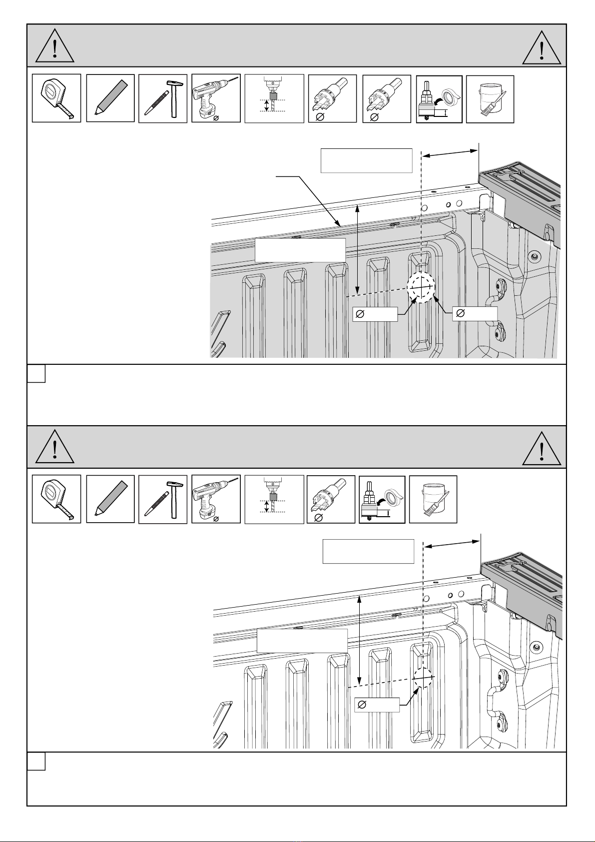
3
FRONT DRAIN TUBES - TUB DRILLING WITH TUBLINER
127mm
185mm
On the tub front panel, measure and markup the positions for the front drain tubes.
Centre punch the locations and drill 5.5mm pilot hole through the tub and tubliner.
Using hole saw drill 60mm hole in the tubliner only, use 10mm stop. With a 38mm hole saw, drill hole in the tub
following the pilot hole. Deburr both holes and apply rust inhibitor to the metal. Repeat for LHS.
4
On the tub front panel, measure and markup the positions for the front drain tubes.
Centre punch the locations and drill 5.5mm pilot hole through the tub.
Using hole saw drill 60mm hole in the tubliner only, With a 38mm hole saw, drill hole in the tub following the pilot
hole use 10mm stop. Deburr both holes and apply rust inhibitor to the metal. Repeat for LHS.
FRONT OF TUB - RHS
FRONT OF TUB - RHS
DRILL STOP 10mm
DRILL STOP 10mm
TUBLINER
5.5mm 38mm
60mm
60mm
38mm
ANTI RUST
10mm
FRONT DRAIN TUBES - TUB DRILLING (NO TUBLINER)
5.5mm 38mm
ANTI RUST
10mm
127mm
185mm
38mm
-- EGR Document ID#121541 v5 2023-05-09 23:59:32 awilmott --

Page 13 of 33ISSUE 4: 26/04/23 RT0063
105mm
40mm
5
On the tub rear panel, measure and markup the positions for the rear drain tubes.
Centre punch the locations and drill 5.5mm pilot hole through the tubliner ONLY!
Using hole saw drill 29mm hole in the tubliner. Use 10mm stop. Repeat for LHS.
REAR OF TUB - RHS
DRILL STOP 10mm
TUBLINER
TUBLINER
300mm
5.5mm 29mm
EGR ROLLTRAC SPECIFIC DDK’S ARE AVAILABLE FROM YOUR DEALER.
IF A DDK IS TO BE INSTALLED, IT SHOULD BE FITTED AFTER INSTALLING EGR ROLLTRAC.
NOTE THAT IF DDK IS TO BE INSTALLED, DRILLING AT REAR OF TUB IS NOT REQUIRED.
10mm
29mm
REAR DRAIN TUBES - TUBLINER FITTED (NO DDK)
STEP 5 & 6
6
RHS & LHS
Trim the drain tube conduit as shown and fit from the outside of the tubliner in through the drilled hole. Spray tubes
with soapy water to help with fitment. Repeat for LHS.
2
1
31
SECTION VIEW
-- EGR Document ID#121541 v5 2023-05-09 23:59:32 awilmott --

Page 14 of 33ISSUE 4: 26/04/23 RT0063
105mm
40mm
On the tub rear panel, measure and markup the positions for the rear drain tubes.
Centre punch the locations and drill 5.5mm pilot hole through the tub.
Using hole saw drill 29mm hole in the tub. Use 10mm stop. Repeat for LHS.
REAR OF TUB - RHS
5.5mm
DRILL STOP 10mm
29mm
ANTI RUST
7
8
10mm
REAR DRAIN TUBES - TUB DRILLING (NO TUBLINER & NO DDK)
STEP 7 & 8
RHS & LHS
Fit the rear drain tubes from the inside of the tail lamp cavity up through the drilled hole. Spray tubes with soapy water
to help with fitment. Repeat for LHS.
2
1
31
-- EGR Document ID#121541 v5 2023-05-09 23:59:32 awilmott --
Cutting device
needed to trim
bed cap
Page 15 of 33ISSUE 4: 26/04/23 RT0063
21
9
13mm
A
Inside the tub locate the RHS bed cap and cover the inside face with masking tape to allow marking with pen and
avoid scratching during trimming. Mark the bed cap as shown above and trim the area using suitable tool.
If CMS rail fitted, remove the 4 M6 screws as shown. Repeat for LHS.
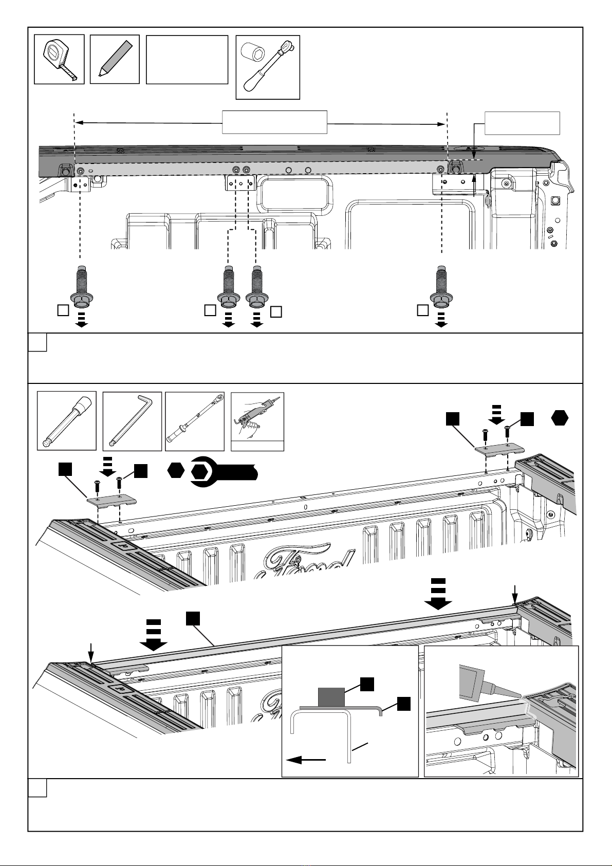
Fit the two h-bar corner brackets (9) to the top of the front of the tub and secure with two screws (21). Repeat for the
LHS. Apply the front rail seal (17) along the top of the h-bar as shown and ensure ends touch the endcap. Apply
Silicone in the gap between the rail seal, bracket and tub rail as shown. NOTE: Seal all holes in the tub as required.
BED CAP - RHS
9
10
34mm
947mm
AAA
17
9
x2
21
x2
22Nm
1
1
1
5mm 5mm
17
9
FRONT TUB
SECTION VIEW
SEAL TOUCH
SEAL TOUCH
NOT SUPPLIED
-- EGR Document ID#121541 v5 2023-05-09 23:59:32 awilmott --

Page 16 of 33ISSUE 4: 26/04/23 RT0063
19 18
13mm
Fit the 4 screws (19) into the RHS mounting rail (6) and fit the end pads as shown. Set the screws height as shown
in detail. Repeat for the LHS mounting rail.
NOTE: Screws will be adjusted in later stage once fitted to the tub.
MNT BAR - RHS
MNT BAR - LHS
11
x4
19
x4
x4
18
x4
5
6
SET SCREW HEIGHT
-- EGR Document ID#121541 v5 2023-05-09 23:59:32 awilmott --

Page 17 of 33ISSUE 4: 26/04/23 RT0063
19
18
Fit the RHS mounting bar to the tub as shown. Secure with 4 screws (20) and nuts (25). Torque to 5.5Nm.
NOTE: Level the bar by pushing it up till it contacts the tub (see section view).
Turn the screw (19) up until the cap (18) contacts the inner tub sheet metal (see section view). Do not overtighten.
12
1
5.5Nm
1
4mm 4mm
MNT BAR - RHS
NOT REQUIRED IF CMS BAR BRACKETS FITTED
6
6
20
25
x4
x4
SECTION VIEW
TUB
BED CAP
-- EGR Document ID#121541 v5 2023-05-09 23:59:32 awilmott --

Page 18 of 33ISSUE 4: 26/04/23 RT0063
21
22
24
24
Fit the RHS rear mounting bracket to the tub and secure with 2 screws (21) and (22) as shown.
Use 2x spacers (24) behind the bracket (screw (21) location) and 1x spacer (screw (22) location).
Torque to 13.5Nm & 5.5Nm. Repeat for LHS.
NOTE: Clearance hole may have to be drilled in the tubliner for the spacer (24).
13
29mm 10mm
1
2
13.5Nm
1
5.5Nm
2
4mm 4mm
14
x2
14
Connect the front drain tubes (8) to the tub. Make sure that both tubes engage over the wall of the tub. Leakage will
occur if they are not properly installed.
INSTALL FRONT DRAIN TUBES TO TUB
21
28
28
29mm
-- EGR Document ID#121541 v5 2023-05-09 23:59:32 awilmott --

RT0063
Page 19 of 33
ISSUE 4: 26/04/23
EGR RollTrac ASSEMBLY
SECTION C
RHS
FIT FIRST
LHS
4
3
1
1
4mm
DURING ASSEMBLY PROCEDURE SUPPORT AT CENTRE OF CANISTER ONLY,
PLACE ON TOP AND BASE CARTON (OR SIMILAR), COVER WITH FOAM BLANKET.
TO AVOID SCRATCHING POWDERCOATED SURFACES.
DO NOT LOAD ELECTRICAL CONNECTORS OR MOTOR COVER.
Place the canister (1) on two protected boxes as shown, ensure hand rail and slat ends are aligned. Tape up the seal
on the Side Rail (3) as shown.
IMPORTANT: Carefully align and slide the rail over the handrail and canister endplate taking particular care to ensure
that the siderails are slid straight and no undue force is applied to the rail. Details in following steps.
APPROX
300mm
HOLD SEAL FLAT
USE CLOTH TAPE
RHS SHOWN
1ATTENTION: SEAL MUST FACE IN THE
DIRECTION AS SHOWN. WARRANTY VOID IF
ASSEMBLED INCORRECTLY.
ENSURE ENDS ARE
ALIGNED & CENTRED
2ATTENTION: EXPOSE 3 SLATS PRIOR TO
FITTING SIDE RAILS.
C/L
-- EGR Document ID#121541 v5 2023-05-09 23:59:32 awilmott --

RT0063
ISSUE 4: 26/04/23 Page 20 of 33
ALIGN CAREFULLY
CAUTION
REMOVE THE TAPE FROM TOP OF THE RAIL
AND PULL OUT HORIZONTALLY
CHECK SEAL IS IN POSITION AND NOT DAMAGED
Carefully lay the assembly over onto a protected surface. Remove the tape holding the rubber seal and check the seal
position as shown.
3
DURING ASSEMBLY PROCEDURE SUPPORT AT CENTRE OF CANISTER ONLY,
PLACE ON TOP AND BASE CARTON (OR SIMILAR), COVER WITH FOAM BLANKET.
TO AVOID SCRATCHING POWDERCOATED SURFACES.
DO NOT LOAD ELECTRICAL CONNECTORS OR MOTOR COVER.
45
TUCK LOOM TO THE SIDE
FIT
20
SLIDE INTO POSITION ALIGN HOLES
GENTLY WIGGLING THE PART INTO THE FINAL
POSITION MAY HELP
INSERT SCREWS AND TIGHTEN LOOSELY
ALIGN
HOLES
90°
Pull hand rail to expose 3 slats. Slide the side rail over slat ends and onto endcap location pins. Align the holes and
secure loosely with a M6x15mm screw (20). Do not tighten. Repeat for LHS Rail.
2
3
ATTENTION: SEAL MUST FACE IN THE
DIRECTION AS SHOWN. WARRANTY VOID IF
ASSEMBLED INCORRECTLY.
2
1
-- EGR Document ID#121541 v5 2023-05-09 23:59:32 awilmott --
Other manuals for RollTrac
2
Table of contents
Other EGR Automobile Accessories manuals


Popular Automobile Accessories manuals by other brands


Whispbar
Whispbar K666 manual

Torklift
Torklift C4201 Important owner-operator installation instructions

Rigid Industries
Rigid Industries E Series installation instructions

Metra Electronics
Metra Electronics 95-7298B installation instructions

Parrot
Parrot Easydrive user guide

Guardsman
Guardsman G1460 FITTING INSTRUCTION

POOL-LINE
POOL-LINE 110003 Assembly instructions

Eaton
Eaton VORAD AlwaysAlert installation guide

Discount Car Stereo
Discount Car Stereo PXDX-CTS Quick start installation guide

Road Angel
Road Angel RA8100 User's installation guide

Lippert
Lippert SolidStep Gen 2 Installation and owner's manual

tams elektronik
tams elektronik FCS-2 manual