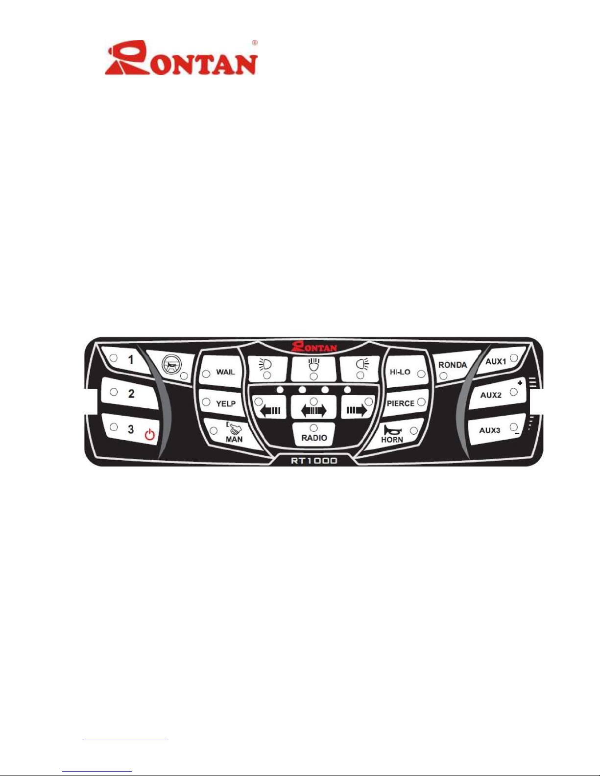
Rontan RT-1000 Owner's manual

RT-1000
Installation, Operation and Programming Manual
1
www.rontan.com REV1.1
Introduction
The RT-1000 is a 50W / 100W amplifier created to command all the visual and
acoustic functions of a vehicle adapted with lightbar(s) and siren. It possesses digital
input and outputs that permit the activation of these functions as well as intelligent
battery consumption management.
General Description
Siren of 100W RMS (speaker of 11Ω) or 50W RMS (speaker of 8Ω);
Made for operation in 12Vor 24V systems (2 distinct models);
Radio input;
Input for the signal of the siren selection (undercover vehicles);
Twenty-one command keys with LED activation indicator;
Four LEDs that indicate the operational state;
External fuse in the rear panel;
Hands free input and output;
Eight digital outputs (250 mA);
Input for Pos-Ignition;
Input for the I-Saver (automatic shut-off after 4 hours);
Input for activation of the backlight of the panel;
Digital communication interface with Rontan lightbars;
Battery management system;
Digital Radio Volume control.

RT-1000
Installation, Operation and Programming Manual
2
www.rontan.com REV1.1
Safety Message
WARNING
Before beginning installation of your device, it is important to read these
instructions for the safe/correct installation and operation of this product.
Proper installation of this product requires the installer have good
understanding of automotive electrical systems and procedures.
DO NOT route any wires in the deployment path of your airbag. Refer to the
vehicle owner’s manual for the airbag deployment area.
DO NOT drill any holes into the device.
If it is necessary to perform a battery charge with an auxiliary car battery, it is highly
recommended to disconnect the alimentation of the product to avoid a surge in
voltage that may damage the unit and the electrical system of the vehicle. DO NOT
jumpstart the vehicle with the battery connected to the siren and lightbar system.
Auxiliary lights and sirens are intended for use by authorized personnel only.
The user has the responsibility to ensure they operate the emergency warning
devices in compliance with the applicable laws and regulations.
File these instructions in a safe place and refer to them when performing
maintenance and/or reinstallation of this product.
Failure to follow all safety precautions could result in damage to the product
and vehicle or serious injury to individuals!

RT-1000
Installation, Operation and Programming Manual
3
www.rontan.com REV1.1
Application
The RT-1000 is an amplifier that can be installed in diverse vehicles like
ambulances, rescue vehicles, patrol vehicles, service vehicles or whatever other vehicle
needs visual or acoustic communication, and can be used to control:
Lightbars;
Auxiliary lights;
Strobe lights;
Takedown and alley lights;
Directionalstick lights for controlling traffic.
Front Panel
The front panel is a keyboard composed of 21 keys for momentary or permanent
(Figure 1) activation according with each function, through which the user commands
the functions of the equipment.
Figure 1: Front panel

RT-1000
Installation, Operation and Programming Manual
4
www.rontan.com REV1.1
Rear Panel
The Rear Panel of the RT1000 possesses 8 connectors identified below:
Figure 2: Rear Panel
Connector
Function
Pin
Wire Color
Description
Power
1
Black
Negative terminal of the battery
2
Red
Positive terminal of the battery
Siren output
1
Brown
50 or 100W Common GND
2
Green
Output for the 50W siren
3
Yellow
Output for the 100W siren
Lightbar and
Hands Free
1
Yellow
Lightbar
2
Orange
Lightbar
3
-
Not used
4
Blue
N.C. of the Relay
5
Grey
N.O. of the Relay
6
White with blue
COM. Activation of relay and Hands Free functions
Inputs
1
Orange
Input 1 –Activate flash pattern SL3 in the lightbar
2
Yellow
Input 2 –Activate siren sound HORN
3
Green
Input 3 –Activate siren sound MAN
4
Blue
External activation of siren sounds
5
Purple
Activation of the I-Saver function
6
Grey
Activates the illumination of the keys of the panel
7
White
Activates the cancelling of all the siren sounds
8
White with black
Input of the Pos-Ignition
9
Brown
Inputs of the radio connections
10
Brown
Outputs
1
-
Output 1 activated by key “1”
2
-
Output 2 activated by key “2”
3
-
Output 3 activated by key “3”
4
-
Output 4 activated by key “AUX1”
5
-
Output 5 activated by key “AUX2”
6
-
Output 6 activated by key “AUX3”
7
-
Output 7 activated by the function “Low-Bat”
8
-
Output 8 –Not used
Microfone PTT
-
Cable extension
Input for PTT microphone
Remote panel
Not used
Fuse
-
-
Blade type fuse 15A
Table 1: Description of the connectors

RT-1000
Installation, Operation and Programming Manual
5
www.rontan.com REV1.1
Input/Output
Parameter
Condition and/or
version
Mín.
Max.
Unit
VS
Power Voltage
12V
10,8
14,7
V
24V
21,9
29,4
IS
Power Current
12V
-
9,5
A
24V
-
4,2
I Stby
Standby Current
12/24V
<0,001
A
V IGN
Ignition Input Voltage
12/24V
>1,8
V
V BCKLT
Backlight Input Voltage
12/24V
>1,8
V
V Radio
Audio Voltage of the Radio Input
12/24V
-
5
Vpp
I-Out1 - 8
Output Current –Outputs 1 to 8
12/24V
-
250
mA
V OUT SIR
50W Siren Output Voltage
12/24V
-
44
Vpp
100W Siren Output Voltage
-
69
P OUT SIR
Siren Output Power
12/24V @ VS Max.
(output 50W/8Ω)
-
50
W
RMS
12/24V @ VS Max.
(output 100W/11Ω)
-
100
T Stg
Storage Temperature
-
-20
80
ºC
Table 2: Electrical and Thermal Characteristics
Compatibility
The RT-1000 is a device compatible with Rontan digital lightbars.
Installation
The installation of this equipment should be accomplished by an experienced
technician to avoid accidents and damage to the equipment and vehicle.
Carefully read these chapters carefully before beginning installation.

RT-1000
Installation, Operation and Programming Manual
6
www.rontan.com REV1.1
The instructions contained in these chapters guarantee the minimum safety
conditions for the installation of this equipment.
Conexões e Chicotes
Together with the equipment are supplied pigtails with connectors to make each
wiring harness. (Example shown in the enhanced area in figure 3). It is of extreme
importance that the sections about wires in Table 3 be respected and followed closely.
Connection
Wire
Section
Voltage
14 AWG
2.0 mm²
Siren Output
14 AWG
2.0 mm²
Connector 1
20 AWG
0.5 mm²
Connector 2
20 AWG
0.5 mm²
Table 3: Section of the wires for connection
A fuse should be added to the wiring harness (Figure 3) close to the battery to
prevent damage to the electrical system of the car by short circuit.
Figure 3 –Connections and wiring harnesses

RT-1000
Installation, Operation and Programming Manual
7
www.rontan.com REV1.1
Diagram of connections for the Panel of the Vehicle
Figure 4: Diagram of the basic connections
External Siren (input of signal for siren selection)
This input is a signal to select between tones of the siren, normally it is used in
undercover vehicles. This should be connected to a ground through a momentary
selection switch, each pulse of this switch will navigate between the tones Pierce > Yelp
> Hi-Lo > Wail > Off. Maintaining the switch pressed for more than a second and a half,
turns the siren off.

RT-1000
Installation, Operation and Programming Manual
8
www.rontan.com REV1.1
Basic connection diagram:
Figure 5: External siren Figure 6: External siren
Connection Schematic Switch Connection Schematic
Sequence
Tones
1
PIERCE
2
YELP
3
HI-LO
4
WAIL
5
OFF
Table 4: Sequence of tones –External siren
Input External Siren
Ação
12/24V
None
Open (avoid)
None
Pulsed to GND
Change siren tone
Table 5: Input logic of the External Siren
Input for Hands Free function
The RT1000 possesses a button in the front panel used to activate the Hands
Free function. When this function is active the internal relay will be activated,
deactivating the horn, and making the horn button function as the siren selector
according to table 6.
NOTE: When this function is active, the vehicle horn will not function.
To deactivate the Hands Free function, press the same button on the panel again.

RT-1000
Installation, Operation and Programming Manual
9
www.rontan.com REV1.1
Basic connection diagrama:
Figure 7: Connection Schematic
Sequence
Types of sounds
1
WAIL
2
YELP
3
HI-LO
4
PIERCE
5
OFF
Table 6: Sequence of the siren sounds
IGNITION input
The IGNITION input should be connected to the vehicle key switch, in the fashion
that the equipment only functions when the key switch is on. If the user does not want
to use this function, this input should be connected to power (+12 or +24V). Table 7
shows the logical functioning of the input together with the I-Saver feature.
I-Saver Input
If this input is activated the moment that the function IGNITION is activated, the
siren will wait for 4 hours before deactivating. This function is activated when
connected to the battery positive.
IGNITION Input
Status of the RT-1000
with the I-saver input
OPEN or GND
Status of the RT-1000
with I-saver on +BAT
+ BAT
On
On
Open (avoid)
Off
Waits 4 hours before
turning off
GND
Off
Waits 4 hours before
turning off
Table 7: Logic of the IGNITION and I-SAVER inputs

RT-1000
Installation, Operation and Programming Manual
10
www.rontan.com REV1.1
Figure 8: Schematic of connection of the function IGNITION together with I-SAVER
BACKLIGHT Input
The BACKLIGHT input should be connected to the headlight power when you
wish to have the backlight illuminated when the vehicle headlights are on. Table 8
shows the logical function of the input.
BACKLIGHT INPUT
BACKLIGHT
+BAT
On
Open (avoid)
Off
GND
Off
Table 8: Logic of the BACKLIGHT input
Battery management function:
The LED indicator of the low battery will be activated if the power voltage reaches
the critical level of 10.9V for the 12V model and 21.9V for the 24V model, for more than
25 seconds. At this voltage it is still possible to start the vehicle. Once the LED is on, all
the functions are turned off. Take this chance to start the vehicle to recharge the
battery.
IMPORTANT: In situations when it is necessary to use the functions of the RT-
1000, even when the battery is low, the users need simply press the button of the
function he/she desires and the equipment will function as normal. The Low Bat LED
will remain lit until the level of the battery is 13.3V for the 12V model and 26.6 for the
24V model.
Low Bat LED indicator

RT-1000
Installation, Operation and Programming Manual
11
www.rontan.com REV1.1
Battery Voltage (VBAT)
LED Indicator
RT-1000 12V
RT-1000 24V
≥10,9V
≥21,9V
Off
<10,9V
<21,9V
Lit after 25s
≥13,3V
≥26,6V
Off
Table 9: Logic of the low battery function
Low Bat –Output 7 (low battery signal)
Similar to the battery management system, this output will be activated (+12 or
+24V) if the power voltage falls below the critical level of 10.9V for the 12V model and
21,9V for the 24V model for 19 seconds. At this level it is possible to still start the
vehicle.
This output will only be deactivated when the voltage returns to a level of 13.3V
for the 12V model and 26.6V for the 24V model.
This output allows you to trigger some external device, for example alarms, relays, etc.
The power of this output is limited to 250 mA.
This output, associated with the front LED (previous topic), signals that the battery is at
the critical threshold. See table 10 below, the voltage values for both amp models:
Battery Voltage (VBAT)
Output 7
RT-1000 12V
RT-1000 24V
≥10,85V
≥21,7V
Off
<10,85V
<21,7
Activates after 19 seg.
≥12,9V
≥26,6V
Deactivates after 19 seg.
Table 10: Voltage limits
Table 11 below summarizes the functions of battery management (LED indicator) and
Low Bat (Output 7):
Model
Function
Power to
Activate
Time to
Activate
Power to
Deactivate
Time to
Deactivate
RT-1000 12V
Output 7
<10,85V
19s
>12,9V
19s
LED indicador
<10,9V
25s
>13,3V
Instantly
RT-1000 24V
Output 7
<21,7V
19s
>26,6V
19s
LED indicador
<21,9V
25s
>26,6V
Instantly
Table 11: Power Management

RT-1000
Installation, Operation and Programming Manual
12
www.rontan.com REV1.1
Radio Inputs
RADIO 1 and RADIO 2 inputs must be connected to the audio outputs of the radio
to be amplified in the siren output when the RADIO function is enabled in the
Panel. To adjust the volume of the siren output function a secondary volume
adjustment is used and located on the buttons AUX2 (increase) and AUX3
(decrease). See Figure 9. To adjust the volume, press and hold for more than 1s a
while the RADIO function is triggered or while speaking into the microphone with
PTT pressed.
Figura 9: Volume adjustment
Figure 10: Insertion and removal of the equipment from the vehicle

RT-1000
Installation, Operation and Programming Manual
13
www.rontan.com REV1.1
Dimensions
Figure 11: Dimensions of the RT-1000
Figure 12: Dimensions of the mounting sleeve

RT-1000
Installation, Operation and Programming Manual
14
www.rontan.com REV1.1
Operation modes
Operation of the Front Panel:
Button
Function
Outputs and functions enabled
1
Activates lightbar in SL1 mode turns off buttons 2 & 3
Activates the digital output 1 (**)
2
Activates lightbar in SL3 mode turns off buttons 1 & 3
Activates the digital output 2 (**)
3
Activates lightbar in SL3 mode turns off buttons 1 & 2, activates
WAIL function
Activates the digital output 3 (***)
RONDA
Activates the patrol function of the lightbar (Only blocks from
the light ends in low intensity).
WAIL
Randomly activates Siren tones
YELP
Audio output
HI-LO
PIERCE
Activates the Hands Free
Audio output and activates internal relay
Activates the right directional function
Digital connected to Rontan lightbars
Activates the left directional function
Digital connected to Rontan lightbars
Activates the central directional and hazard function
Digital connected to Rontan lightbars
Activates the left service light
Digital connected to Rontan lightbars
Activates the right service light
Digital connected to Rontan lightbars
Activates the front service light
Digital connected to Rontan lightbars
RADIO
Amplifies the sound from the radio to the siren output
Audio output
AUX1
Output 4
Turns on digital output Output 4
AUX2
Output 5 and increase volume (if pressed for more than 1.5s)
Turns on digital output Output 5 (*)
AUX3
Output 6 and decrease volume (if pressed for more than 1.5s)
Turns on digital output Output 6 (*)
Table 12: Description of the function of the front panel
(*)The secondary volume adjustment function is enabled only when the
microphone PTT button is pressed or the Radio function is active.
(**)To activate the buttons 1 or 2, if the 3 button is activated, it will be shut down
along with the buttons WAIL, YELP, HI-LO and PIERCE.
(***)If this button is pressed for more than 1.5 s, the equipment will restart,
shutting down all functions that are activated.

RT-1000
Installation, Operation and Programming Manual
15
www.rontan.com REV1.1
Error Identification
If there is a malfunction of the equipment, this will be indicated by four LEDS in
the center panel. Table 13 brings the meaning of each one of the indications and the
solution to the problem stated.
LEDs
Error meaning
Action
●○○○
Low battery voltage
Start the vehicle or verify the
battery
○●●○
Short circuit in the output of the
siren, or temperature overload
Check the siren, speaker and
connections
●○○●
○●●○
Switching between these two
errors, indicates overload in
power supply
Check the supply voltage of the
equipment
Table 13: Identification of errors
Warranty message
For warranty information regarding this product, please visit:
www.rontantech.com/eng/warranty
Table of contents
Other Rontan Car Amplifier manuals