Easy
Edition
3
400x300
cm
V
RS
400300-07/18EN
EN
-
Installation
Guide:
Contents
of
Packaging
Open
the
packaging with caution
!!!
Check
for
missing or
damaged
contents
!!!
In the
case
of
shipping
damage,
make
photos
and
contact
your
dealer
!!!
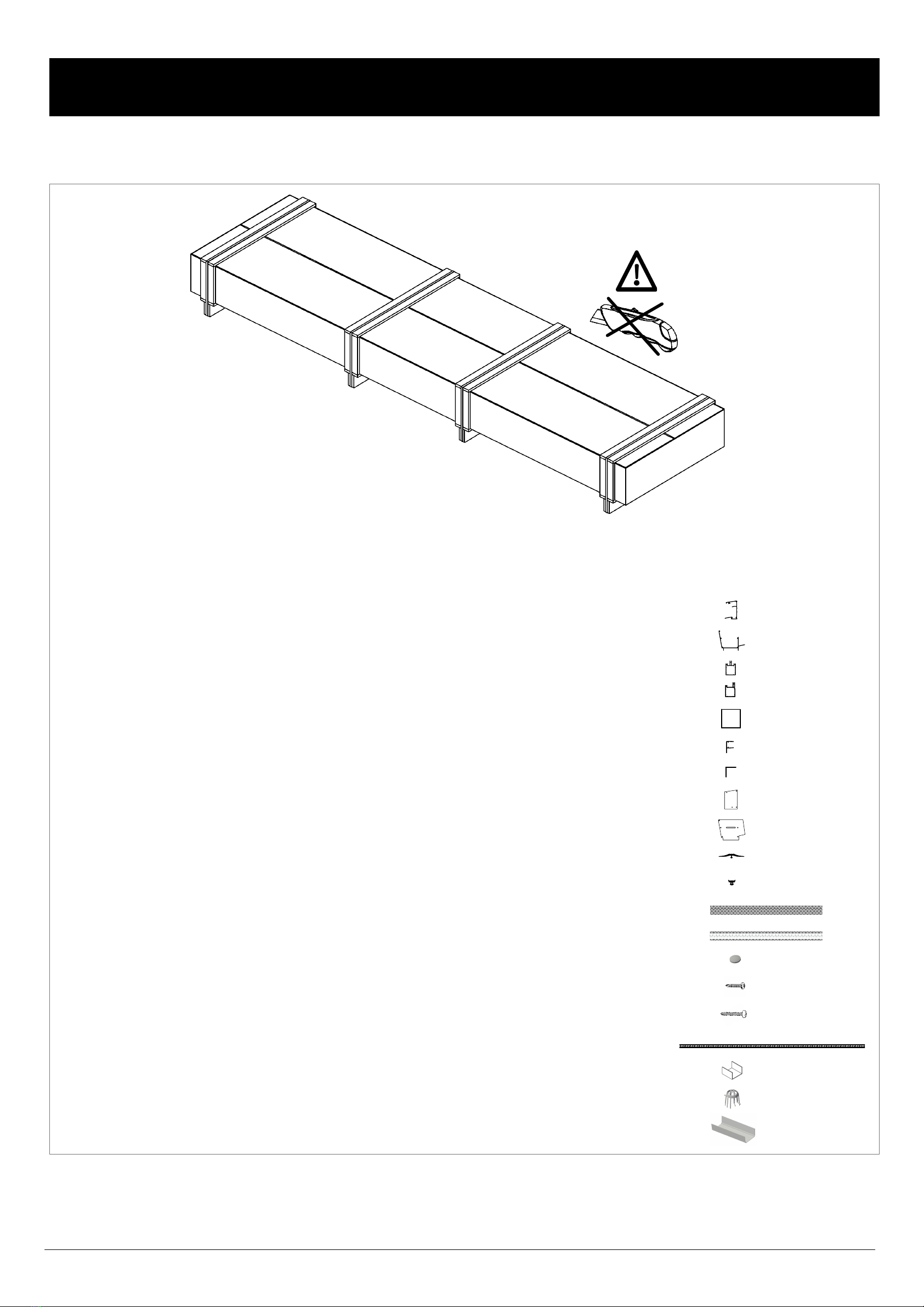
PACKAGE
CONTENTS:
Article
number:
100.1140100.1141100.1142100.1177100.1017100.1057102.1307102.1306102.1305106.1018106.1001102.1018102.1017102.1188103.1000103.1002111.1001100.1308102.1169102.1317
Number:
2000 mm.2200 mm.2950 mm.2950 mm.2400 mm.980 mm.
piecespiecespieces
metermetermetermeter
piecespiecespieces
3000 mm.
piecespiecespieces
Description:
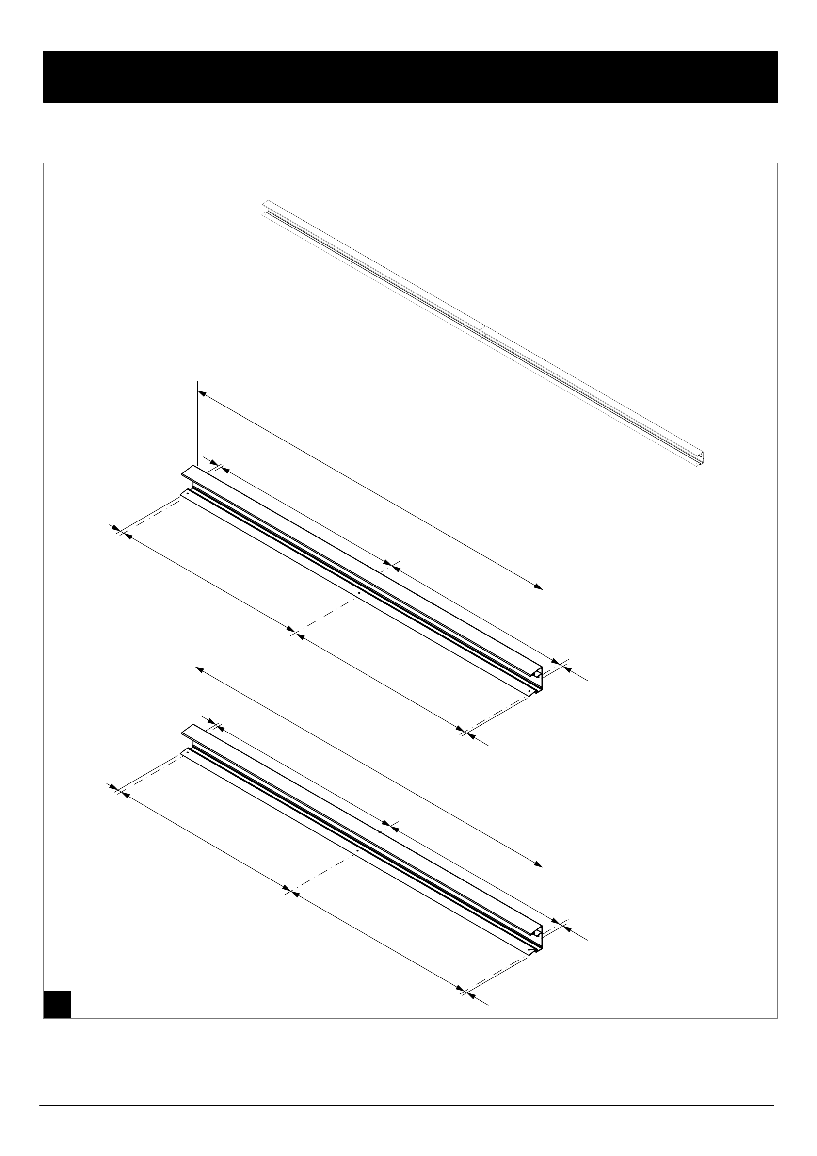
Wall
profile
Gutter
profile
Intermediate
support
profile
Side
support
profile
Post
90x90
mm.
Condensation
profile
Angle
plate
Wall
profile
end
plate
Gutter
profile
end
plate
Rubber
cover
seal
Spaghetti
seal
Anti-dust
tape
Anti-condensation
tape
Cover
for
screw
Screw
4.2x19
Screw
4.2x32
Polycarbonate
opal
980
mm
U
bracket
Leaf
trap
Gutter
connector
Aantal:
223234522164,14,14,19080104311
Figure:
Pos.
:
1234567891011121314151617181920