Rosco Dual-Vision XC4 Manual

1
Dual-Vision™ XC4
Standard Version
Installation & Operating Instructions
19 DEC, 2017
90-21 144th Place, Jamaica, New York USA 11435
Phone: 800-227-2095
www.roscovision.com
Version 5.3
©2017 Rosco® Vision Systems, All Rights Reserved
Specifications and details are subject to change without prior notice.
Patent Pending

2
TABLE OF CONTENTS
For the latest version of the User Manual please visit www.roscovision.com
Safety Instructions..................................................................................................4
Introduction.............................................................................................................5
Package Contents...................................................................................................6
Kit Part #: DV440.......................................................................................................... 6
Features...................................................................................................................7
DVXC4.......................................................................................................................... 7
DATA RETRIEVAL OPTIONS........................................................................................... 7
DV-Pro5 Player (See page 18) ...................................................................................... 8
Recorder Detail .......................................................................................................9
Installation.............................................................................................................10
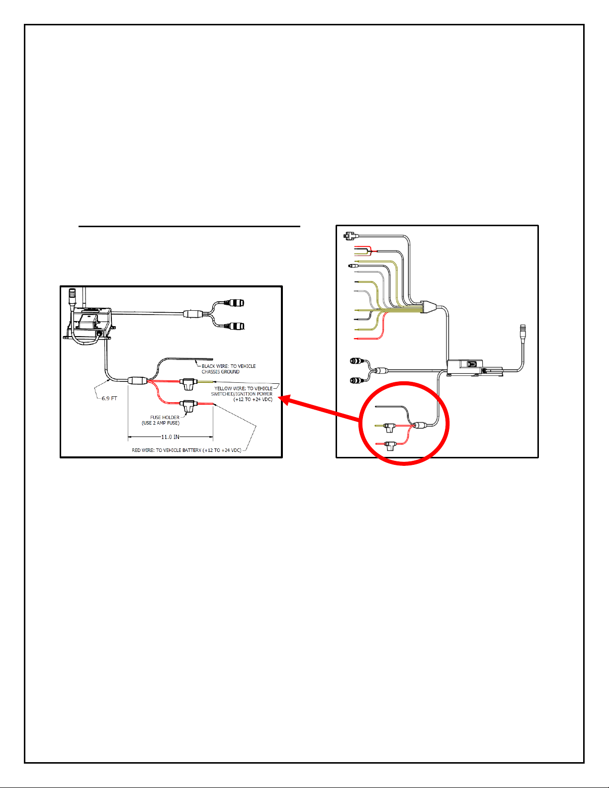
Power wiring diagram................................................................................................ 10
PDC (Power/Data Control) Module Installation ......................................................... 11
Installing Mounting Bracket (DV402) ......................................................................... 12
Mounting the Recorder Unit (DV401) ........................................................................ 13
DVXC4 Operation..................................................................................................15
Drive Recording ......................................................................................................... 15
Continuous and Event Recording............................................................................... 16
Recorder Removal & SD Card Retrieval..............................................................17
DV-Pro5 Player Program.......................................................................................18
Introduction to DV-Pro5 (Standard Version) .............................................................. 18
Install DV-Pro5........................................................................................................... 19
DV-Pro5 Home Screen ............................................................................................... 20
Camera System Setup and Configuration...........................................................21
General Settings......................................................................................................... 22
Channel Settings ........................................................................................................ 23
Event Settings ............................................................................................................ 24
Server Settings........................................................................................................... 25
Remove SD Card from PC & Install into DVXC4 .......................................................... 26
Setting Up and Analyzing G-SENSOR Data.................................................................. 28
G-SENSOR Event Examples in DV-Pro5....................................................................... 29
Backing Up Video Files to Your PC (Import)................................................................ 30
Conversion of Video To AVI........................................................................................ 31
Vehicle Location Map ................................................................................................ 32
Format SD Card using DV-Pro5 .................................................................................. 33
SD Card Maintenance ...........................................................................................34
DVCV4 Hardware Technical Specifications ........................................................35
Engineering Drawings ..........................................................................................36
Application Notes..................................................................................................36

3
Troubleshooting....................................................................................................37
AUX Cameras (Optional).......................................................................................38
Spare Parts............................................................................................................39
Commercial Warranty...........................................................................................40

4
Safety Instructions
To ensure proper operation please read this User Manual
before installation and operation. Failure to follow this safety
notice may cause a malfunction and will void the warranty.
IMPORTANT
FOLLOW PROPER SHUTDOWN PROCEDURE
PRIOR TO UNLOCKING DVXC4 FOR SD CARD
REMOVAL.
(Refer to p. 17)
BEFORE REMOVING DVXC4 FROM
MOUNT, USE SUPPLIED KEYS TO
UNLOCK THE RECORDER. (Refer to p. 17)
ALWAYS USE THE “EJECT”
FEATURE ON YOUR PC PRIOR
TO REMOVING ANY SD CARD
FROM YOUR PC. FAILURE TO
DO SO WILL CORRUPT THE SD CARD. (Refer to p. 25)
CAUTION
THE FOLLOWING ACTIONS WILL VOID WARRANTY AND
MAY CAUSE AN ELECTRICAL SHORT CIRCUIT
DO NOT:
- Clean recorder with any liquids
- Insert foreign materials into the Dual-Vision XC4 device
- Attempt to disassemble, repair or modify the product
- Use cables, SD cards or fuses that are not provided by or recommended by Rosco®
NOTE
GPS The Dual-Vision XC4 Mounting Bracket must be mounted on the windshield in order to
have direct line-of-sight to the sky for reliable GPS satellite signal acquisition.
SD CARD The SD card must be reformatted periodically using the DV-Pro5 menu---Refer to
“SD Card Formatting” section on page 33.

5
Introduction
Dual-Vision XC4 by Rosco provides HD recording of exterior/interior video, and continuously logs
vehicle travel data. Mounted on the windshield, Dual-VisionXC4’s twin cameras capture wide-angle
views of the forward exterior field of vision and the driver/passenger compartment. Privacy concerns
may be addressed through several means, including disabling of interior audio recording.
Data is recorded in a continuous loop, with oldest video erased by more recent video. The compact
system can hold many hours of data before any over-writing takes place. An internal GPS antenna
enables capture of vehicle location, speed, and direction. Important “Events” such as excessive G-
Force and speeding are placed in special protected files along with video segments identified by
the driver as being important.
All the data is stored in proprietary files located on a removable SD card. Video, audio, location
information, and G-force data may ONLY be reviewed by accessing the contents of the SD card
using Rosco’s proprietary DV-Pro5 Player software. The software is provided at no additional
cost to the end-user, and there are no follow-up fees for use or updating of the Player by
authorized users. Critical videos may be converted to standard media-player formats for
transmission to legal or administrative offices.
Security: Dual-Vision XC4 is a commercial grade product designed to be used in a variety of
applications. The Security Lock discourages unauthorized removal of the SD card. Installation via
hard-wire connection to a vehicle’s electrical system discourages tampering and provides
recording capability even after the engine has been shut off.
DV-Pro® Fleet Management Software: Dual-Vision XC4 kits are provided with the standard DV-
Pro5 Player software. For more advanced needs, Rosco has developed DV-Pro5-ADS software, an
exclusive fleet management software program for managing multi-vehicle video recordings and
database management.
Contact Rosco Vision Systems or your authorized dealer for more information.
IMPORTANT
If you have a problem printing this document, please download and install the
latest version of Adobe Reader:
http://www.adobe.com/support/downloads/product.jsp?platform=windows&product=10

6
Package Contents
Kit Part #: DV440
Additional Items possibly included with your order:
•DV405: 4G Cellular Module
•DV406: Wi-Fi Module
•DV407: Wi-Fi Patch Antenna
•DV408: 4G Cellular Antenna
•DV412: Wi-Fi MIMO Screw Mount Antenna
•DV415: Wi-Fi MIMO Antenna Extension Cable (1 meter)
DV404: Advanced PDC:
Advanced version of Power and Data Control
Module
DV401: 2CH RECORDER UNIT
DV443: HARDWARE KIT incl., Temporary & Permanent VHB
Tapes with Primer Pen, Allen Wrench, Two Keys, Four Screws for PDC
mounting, 64GB SD card (DV453) –changed from 32GB to 64GB since
mfg. date code 1703
DV441: EXTERNAL DRIVER
EVENT BUTTON with CABLE
DV402: WINDSHIELD
MOUNTING BRACKET

7
Features
DVXC4
•HD Quality Video Recording
•720p Forward View Camera, 960H Interior Camera
•Optional Auxiliary Cameras
•High accuracy built-in GPS confirms location several times per second
•Built-in G-sensor accelerometer
•Locking mounting bracket protects SD card
•Tamper resistant
•Compatible with current and future high-capacity SD memory cards
•Extended hours of recording time per high capacity SD card
•Built-in infrared LED’s for excellent night interior view
Manual SD card removal
Wi-Fi download to dedicated
fleet-owned server
Remote download and/or live
streaming video via cellular
transmission
DATA RETRIEVAL OPTIONS

8
Video Playback and Data Management
Dual-Vision XC4 captures video/audio/GPS/sensor data and creates proprietary files,
which are only readable when viewed within Rosco DV-Pro5 program, included at no
additional charge with each recorder. DV-Pro5 is provided in one of two versions,
depending on the end-user’s data management scenario.
DV-Pro5 Player (See page 18)
•Proprietary video files
•Advanced playback control –frame speed & volume control, video zooming, full screen playback
•Quad-view playback windows
•Easy video management (organized on local storage media for easy retrieval)
•Historical GPS tracking with Google Street & Satellite Map Integration
•Graphical display of accelerometer values
•Built-in SD card formatting
•Platform for configuring per-vehicle Recorder settings
•Conversion of propriety files to .avi video files for sharing with authorized parties

9
Recorder Detail
1. SD Card Slot (Authorized access only)
6. LCD Display
2. Front Camera (Exterior View)
7. Rear Camera (Interior View)
3. Driver Event Button
8. Infrared Illuminators
4. Windshield Mount Push Locks
9. Microphone
5. Audible Alarm Signal

10
Installation
The complete installation requires a Recorder (equipped with cameras and microphone), a
Recorder Windshield Mount (equipped w power/video/data harness), and a PDC module. The
PDC (Power Data Distribution) Module is connected the vehicle’s power system. The PDC’s role is
to provide regulated power and external video/data connections to the Dual-Vision™ XC4
Recorder. See page 36 for a basic system connection diagram.
- Each vehicle has its own system and features. Please refer to your vehicle’s manual for
details.
- Turn the ignition key off while installing the cables and device.
- Select a secure protected location for the PDC module.
- Make sure to connect Ground wire first!
Power wiring diagram
IMPORTANT NOTE FOR INSTALLER
The DVXC4 Power Data Control Module (PDC) contains three wires—red, black, and yellow. The
yellow wire triggers Parking Surveillance by sensing the moment when the driver shuts the ignition.
Parking Surveillance typically provides recording at a lower frame rate for a pre-configured time
period. Parking Surveillance options are noted in the Configuration menu. In situations where a
manager chooses not to utilize this option, the system must be still wired properly to function. Use
the Configuration choices in DV-Pro5 to disable the Parking Surveillance Mode (see page 21).
Installers must be certain that the yellow wire is secured to the vehicle fuse block at a terminal which
will be at a zero-voltage state when the vehicle ignition key is OFF. A typical location on a fuse block
would be the ACC port for cigarette-lighter power. Please refer to the vehicle manual and fuse block
schematic to identify best locations for DVXC4 power/ignition/ground wire connection points. Zero-
voltage state should be verified using a voltmeter prior to installation.
The PDC module includes internal circuit protection against high current or voltage spikes. It is very
important, however, for the professional installer to include appropriate external fuses.

11
PDC (Power/Data Control) Module Installation
1. Unpack the DVXC4 box and prepare all the parts & tools
necessary for installation.
2. Find the location of the fuse box in the vehicle. Identify the
fuses for connection of the RED POWER wire and the
YELLOW IGNITION wire. Identify appropriate location for
installation of the PDC Module in the vehicle.
3. Identify approximate Dual-Vision™ XC4 Recorder location
on windshield. See page 12.Confirm sufficient cable length
available to connect PDC to the Dual-Vision™ XC4
Recorder. Remove the A-Pillar cover and insert the cable
at the gap between ceiling and windshield.
4. After determining that PDC location is appropriate, trim the
cable length as necessary, and make the following
connections:
a. Connect the BLACK WIRE (GROUND -) with ring
terminal to a chassis ground.
b. Connect the RED wire (POWER +) to a constant –
powered source which will remain live after the
ignition is turned OFF.
c. Connect the YELLOW wire (IGNITION) to an ACC
power source.
EXAMPLE:
Ground Wire Ring
Terminal connected to the
vehicle chassis ground
5. Find a location for the Driver Event Button that can be easily accessed by the driver.
Avoid locations where the button may be inadvertently pressed, such as by the driver’s
knee. Remove the adhesive film and attach the button. Connect the Driver Event Button
plug to the Data Cable Harness attached in the PDC Module. Secure all loose wires and
components with cable ties and reinstall vehicle panels.

12
Installing Mounting Bracket (DV402)
1. IMPORTANT: Installation should only be done when ambient temperature is within 50°F-
100°F (10°C-38°C) to allow proper curing of mounting adhesive pads.
2. Determine the proper Dual-Vision™ XC4 Recorder location on windshield. Typically, the
Recorder is mounted behind and slightly below the mirror.
3. Make sure the interior-facing camera and the LCD display are not obstructed by the mirror.
Different vehicle/windshield combinations allow many other acceptable mounting locations.
The goal is always to minimize forward-viewing obstruction while enabling optimal recorded
images. Dual-Vision™ XC4 Recorder should be level both vertically and horizontally.
4. Clean the windshield glass with commercial glass cleaner. Using the adhesive pad marked
“temporary”, attach Mounting Bracket to windshield and press firmly.
5. After mounting, use the provided Hex Key to loosen the Hex Bolt on the Mounting Bracket.
Adjust Mounting Bracket to a fully vertical position and re-tighten the Hex Bolt.
6. Connect Recorder cable to the PDC Module. For most vehicles, this connection will be
made within the overhead space, and will be covered by the headliner. For additional
security, or for installations on very large windshields, it is advisable to enclose the
connection within a heat shrinkable tube or other protective cover, per your installer’s
suggestion.

13
Mounting the Recorder Unit (DV401)
1. Install the SD Card as shown below. Hook the Recorder onto the top of the bracket and firmly
push the bottom of the Recorder to engage it into the Mount, confirmed by an audible “click”:
(See below)
Properly Assembled Recorder & Mount:
Interior View Left Side View Right Side View
2. Lock the recorder into position by pressing the two side-locks in, prior to turning on Power.
3. Turn the vehicle ignition on, and check that the Recorder LCD display lights up to confirm
proper electrical connection. Confirm that the LCD displays “GPS”, “CH1”, “CH2”, “REC” and
SD CARD

14
time of day. “GPS” might not display if the vehicle is not outdoors. For the first time, it may take
up to 2 minutes for the Recorder to acquire a satellite signal and display “GPS”. (see below)
4. Allow Recorder to run for a few minutes. Turn the vehicle ignition off and confirm the LCD
display dims/blinks slowly, indicating Parking Surveillance Mode. Refer to p.17 to safely
remove the SD card.
5. Review SD card to confirm GPS acquisition and camera views. (See Pages 18-33 for Player
software installation and video playback instructions). Open DV-Pro5 on a PC, then insert the
SD card into the PC’s SD card slot or reader. At that time, the files on the test SD card will pop
up. Click to view test video. If the video recording indicates that Recorder location is not
acceptable, adjust the bracket angle and/or re-position bracket, and test again. If the Recorder
placement is acceptable, proceed to the next step for permanent installation.
6. Use a Nylon Pry Tool to carefully peel off the temporary adhesive pad and remove the
Mounting Bracket. Clean the windshield. Break open the glass primer ampoule and apply a
layer of 3M Primer on the surfaces of both the Windshield Mounting Bracket and the
windshield. Let the primer dry for at least two minutes. Attach the permanent adhesive pad to
the Windshield Mounting Bracket, and then carefully press the assembly onto the windshield,
holding it in place with pressure for about 30 seconds.
7. Do not re-mount Recorder yet. After permanently attaching the Mounting Bracket, allow at
least 2 hours at room temperature to make sure that the adhesive properly cures. Then make
sure there is an appropriate SD card inserted into the back of the Recorder, and proceed to
“clip-in” the Recorder body into the Mounting Bracket. You are now ready to begin recording.
IMPORTANT
Installation of permanent mounting should only be done when windshield is at room
temperature. Allow 2-4 hours for adhesive bond to cure properly before operating vehicle.

15
DVXC4 Operation
Drive Recording
•Your DVXC4 is supplied with an SD card pre-configured with factory default settings (see
page 22-25). Insert the SD card into a PC and add identifying information. Of course, you
may also change the values of any configurable setting as desired. Make sure to “SAVE” as
instructed on page 25.
•After re-inserting the SD card into the back of the Recorder, proceed to “click-in” the
Recorder into the Mounting Bracket as previously described.
•Turn the ignition on. “boot” will appear on the LCD display indicating that the Recorder is
initializing. Approximately 30 seconds after powering on, the LCD will briefly display “F1XX”
indicating the firmware version, and a chime will sound indicating that initialization is
complete. Although GPS still may not be active, recording begins when “REC” is displayed.
•Within two minutes of start (assuming outdoor location), the GPS signal will be acquired, and
the GPS icon will light up. Subsequent vehicle starts will acquire GPS signal significantly
faster than the original start-up. GPS location data will be continuously analyzed, and each
video file will contain embedded location, speed and direction data.
NOTE: When the vehicle is in motion, the LCD displays vehicle speed. When the vehicle comes
to a complete stop, the LCD speed indicator will display the time after a few seconds. The
option to show speed can be disabled by changing the SD card configuration (See Page 22)

16
Continuous and Event Recording
Continuous (Normal) Recording
•When the ignition is OFF, Dual-Vision™ XC4 Recorder remains powered for an additional 5
seconds to finish recording. If Parking Surveillance is ON, LCD Display will show “PARK” icon
on and count-down the parking time in minutes and the LCD will be blinking and dimming
slowly and the recording will be continued until the parking time ends.
•Dual-Vision™ XC4 creates proprietary files (identified as “.nvr” files) which contain video, audio,
and tracking data. Proprietary .nvr files will only playback on DV-Pro5 Player program.
•Continuously recorded .nvr files are NOT protected against overwriting. When the capacity of the
SD Card has been reached, the oldest non-Event files are overwritten.
Event Recording
•Event Recording –When a preconfigured speed or G-sensor values are exceeded, or when
Driver Event Button is pressed, an “EVENT” is created. That is, the .nvr file associated with that
Event is marked and protected against overwriting.
•Event files may be locked or unlocked via the SD Card configuration (See Page 24).
oIf Event Locking is enabled, new event files will be created until they fill up about 25%
of the SD card space. Those first event files will never be overwritten and the DVXC4
LCD will display “FULL”. However, the remaining 75% of the card will continue to
record normal continuous video and overwrite as needed. New event files will be
treated as normal continuous video files and will be overwritten by normal continuous
files. In order to remove the locked files, the card will need to be formatted (See page
33).
oBy default, Event Locking is disabled in the SD card configuration.New event files
will be created until they fill up about 25% of the SD card space. The newest event files
will then overwrite the oldest files (a FIFO queue, first-in first-out). It is strongly
recommended that event locking is left disabled in order to preserve the newest
event files for the maximum amount of time without user intervention.
Speeding Events
G-Sensor Events
Driver Button Events
Parking Mode Denoted
Normal Continuous Video

17
Recorder Removal & SD Card Retrieval
IMPORTANT: FOLLOW PROPER SHUTDOWN PROCEDURE.
RECORDER MUST BE COMPLETELY POWERED OFF
BEFORE DETACHING RECORDER OR REMOVING SD CARD.
ALWAYS power off the vehicle prior to removal of SD Card from Dual-Vision™ XC4 Recorder.
•If parking surveillance mode is OFF, turn ignition off. It is safe to remove the SD card after
the Recorder’s LCD display turns off.
•If parking surveillance mode is ON, turn ignition off and wait for few seconds until the
LCD display begins blinking/dimming. Then press and hold the Driver Event Button for at
least 5 seconds until the LCD indicates “SHUt”, and then goes dark. It is now safe to
remove the recorder and SD card as shown below.
BEFORE REMOVING RECORDER FROM MOUNT, USE THE
SUPPLIED KEYS TO UNLOCK THE RECORDER (STEP 1
BELOW).
SD CARD
Press down
and release
SD Card
Grab bottom of
recorder and pull
back as shown.

18
DV-Pro5 Player Program
Introduction to DV-Pro5 (Standard Version)
Note: This manual will only cover the Standard version of DV-Pro5. See the
separate “DV-Pro5 Advanced User Manual” in order to use DV-Pro5 with
advanced wireless features such as WIFI/ADS and cellular 4G LTE
streaming/cloud services.
Use the Standard version of DV-Pro5 to play video files off the DVXC4 SD Card.
The player can simultaneously show 4 channels of video, display a live map, and
show speed, G-sensor data, etc. The player can also be used to format SD cards,
setup user preferences for recording (SD Card Configuration), back-up SD card
files to a computer (Import), or export video to .avi files.
NOTE: DV-Pro5 is compatible with most PC operating systems (Windows 7, 8 and
10). It is currently not compatible with Mac OS-X or Unix-based operating systems.

19
Install DV-Pro5
Your SD card comes pre-loaded with the files required to install DV-Pro5 on your PC. If those files
are not available, please contact Rosco Vision Systems and we will send you the required files.
To install “DV-Pro5” from the SD card, insert the card into PC and click “open folder to view files”.
Then click “DV-Pro-Setup-Basic-5.0.0.xxx.exe” (xxx denotes the latest version) to begin the
installation.
If the below “User Account Control” window opens, click “Yes”. Click “Next” on the subsequent
windows to complete the installation. By default, the program will install to C:\Program Files
(x86)\DV-Pro5, but this can be changed if desired.

20
DV-Pro5 Home Screen
NAME
DESCRIPTION
A
Forward Camera
Channel 1: Displays exterior video recorded through the windshield
B
Interior Camera
Channel 2: Displays interior video, typically driver and passengers
C
AUX Camera 1
Channel 3: External camera video, typically a side or backup camera (Optional)
D
AUX Camera 2
Channel 4: External camera video, typically a side or backup camera (Optional)
E
Metadata
Displays video file info including, name, time, vehicle ID, driver and speed etc.
F
G-Force graph
3-axis graphic displays vehicle motion and any impacts detected by the G-Sensor
G
Playback Time
Counting video playback time
H
Calendar
Click this icon to open a calendar view of all recorded video. The days with recorded video will be
circled. Double click a day to list that day’s (up to 24 hours) video files. You may also click the arrows
on either side of the date to move forward/backward one day.
I
File List
Displays up to one day (24 hours) of video files in 1-minute segments directly from the SD card or
another location on the computer. Double click on a file to play it. If no video files are shown, click the
“Change” button above the file list to choose the SD Card directory.
J
Playback Menu
Bar
Use to review video. The following controls are available: Playback speed, skip to previous/next video,
step one frame back/forward, rewind/fast forward, pause/play, full screen/window view, zoom, audio
level, brightness and contrast.
K
Map
Shows the vehicle location on a map
L
File Menu Tree
Load SD: Click to load video files from the SD card into the file list
Load Local: Click to load videos from a local directory of the PC/Network Drive/etc.
DV-Pro5 will automatically choose the directory where SD files were last saved to
(see “Import” below).
Import: Click to save video files to a local PC directory/network drive etc
SD Config: Click to review or configure recording preferences
Format SD: Click to format the SD card
Export AVI: Click to Export and save video as an .AVI file
Show Route: Select multiple files and click this button to show the vehicle’s route on
the map
A
C
K
B
J
D
E
G
H
F
L
I
Other manuals for Dual-Vision XC4
4
This manual suits for next models
1
Table of contents