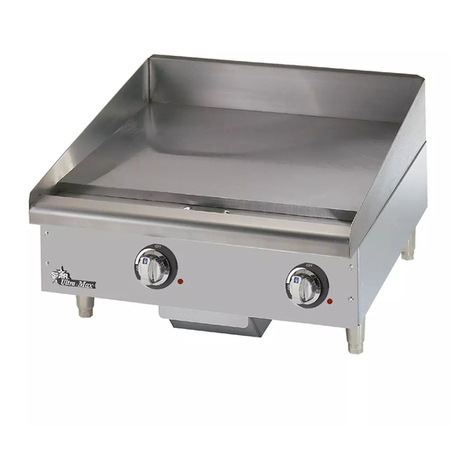
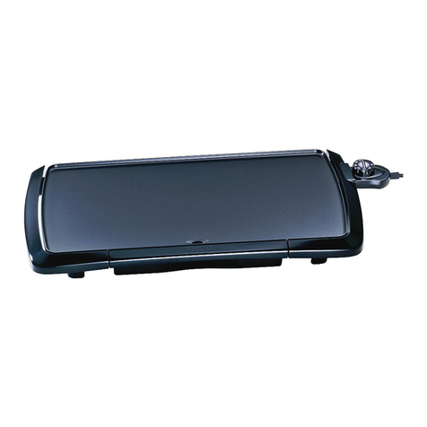
Rosko RO-GCG User manual

RO_GCG_GUIDE (11/21)
EN
Gas Countertop Griddle
RO-GCG
RO-GCG-36
INSTALLATION GUIDE
Operation, Maintenance, and Service Parts
RO-GCG-18 RO-GCG-24 RO-GCG-36
RO-GCG-24-CP RO-GCG-36-CP
955 Lachance Street
Quebec, QC G1P 2H3
Canada
1-866-901-5624
www.rosko-julien.ca

2RO_GCG_GUIDE (11/21)
1. WARNINGS ET CAUTIONS
CAUTION
Any installation, adjustment, modification, repair, or maintenance not in accordance with applicable standards
may cause property damage, injury, or death. To ensure a safe installation and proper operation
of your Rosko equipment, please read this entire guide and keep it for future reference.
•This unit is intended for commercial use only.
•Installation must meet the requirements of the codes below, where applicable:
◽State codes or local codes, or in the absence of local codes:
◽In the United States, national gas code ANSI Z223.1/NFPA 54;
◽In Canada, installation code for natural gas CSA B149.1 or propane gas CSA B149.2;
•Installation of this unit must be done by a qualified person, where required by law.
•Do not store fuels or other flammable materials near the unit.
•Never heat the fry tank when it is empty. This will burn the tank, cause a crack, and void the warranty.
•If a gas odour is detected, shut off the gas power supply at the main source
and then contact the local gas supplier for service.
CAUTION
Keep a copy of these instructions in a visible location1.
1
This guide is updated as new information or new products become available.
Visit our website rosko-julien.ca for the most recent version of these documents.

3RO_GCG_GUIDE (11/21)
TABLE OF CONTENTS
1. WARNINGS ET CAUTIONS . . . . . . . . . . . . . . . . . . . . . . . . . . . . . . . . . . . . . . . . . . . . . . . . . . . . . . . . . . . . . . . . . . . . . . . . . . . . . . . . . . . . . . . . . . . . . . 2
2. PLANNING AND INSTALLATION . . . . . . . . . . . . . . . . . . . . . . . . . . . . . . . . . . . . . . . . . . . . . . . . . . . . . . . . . . . . . . . . . . . . . . . . . . . . . . . . . . . . . . . . . 4
2.1. CLEARANCE ....................................................................................................... . 4
2.2. AIR SUPPLY AND VENTILATION .................................................................................... . 4
2.3. RECEPTION AND INSPECTION ..................................................................................... 4
2.4. LEVEL .............................................................................................................. . 5
2.5. ATTACHEMENT . . . . . . . . . . . . . . . . . . . . . . . . . . . . . . . . . . . . . . . . . . . . . . . . . . . . . . . . . . . . . . . . . . . . . . . . . . . . . . . . . . . . . . . . . . . . . . . . . . . . . 5
2.6. PROPANE GAS CONVERSION ..................................................................................... . 6
2.7. CONNECTION ..................................................................................................... . 9
2.8. GAS PRESSURE CHECK ........................................................................................... 10
3. OPERATION . . . . . . . . . . . . . . . . . . . . . . . . . . . . . . . . . . . . . . . . . . . . . . . . . . . . . . . . . . . . . . . . . . . . . . . . . . . . . . . . . . . . . . . . . . . . . . . . . . . . . . . . . . . . . 11
3.1. IGNITION ............................................................................................................ 11
3.2. BURNER ADJUSTMENT ............................................................................................ 12
3.3. FIRST USE ......................................................................................................... 12
3.4. PROLONGED SHUTDOWN ......................................................................................... 12
4. MAINTENANCE . . . . . . . . . . . . . . . . . . . . . . . . . . . . . . . . . . . . . . . . . . . . . . . . . . . . . . . . . . . . . . . . . . . . . . . . . . . . . . . . . . . . . . . . . . . . . . . . . . . . . . . . 13
4.1. CONDITION ........................................................................................................ 13
4.2. CLEANING ......................................................................................................... 14
5. SERVICE PARTS . . . . . . . . . . . . . . . . . . . . . . . . . . . . . . . . . . . . . . . . . . . . . . . . . . . . . . . . . . . . . . . . . . . . . . . . . . . . . . . . . . . . . . . . . . . . . . . . . . . . . . . . 16
5.1. RO-GCG-18 ........................................................................................................ 16
5.2. RO-GCG-24 ....................................................................................................... 18
5.3. RO-GCG-36 ....................................................................................................... 20
6. SPECIFICATIONS . . . . . . . . . . . . . . . . . . . . . . . . . . . . . . . . . . . . . . . . . . . . . . . . . . . . . . . . . . . . . . . . . . . . . . . . . . . . . . . . . . . . . . . . . . . . . . . . . . . . . . . .22
CONTACT US . . . . . . . . . . . . . . . . . . . . . . . . . . . . . . . . . . . . . . . . . . . . . . . . . . . . . . . . . . . . . . . . . . . . . . . . . . . . . . . . . . . . . . . . . . . . . . . . . . . . . . . . . . . . . 23

4RO_GCG_GUIDE (11/21)
2.PLANNING AND INSTALLATION
Congratulations on purchasing your new Rosko gas countertop griddle!
To maximize the use and durability of your unit, we recommend that you follow the instructions in this guide.
Installation, operation, and maintenance procedures must be followed for warranty protection to apply.
2.1. CLEARANCE
It is essential to observe the following minimum clearance when planning the installation of the unit
and during the installation:
•Construction with combustible materials
◽6” (152 mm) at the back and on each side of the griddle
•Construction with non-combustible materials
◽0” (0 mm) at the back and on each side of the griddle
•Provide adequate space for the unit operation and maintenance
2.2. AIR SUPPLY AND VENTILATION
Leave enough ventilation space above the unit. We recommend placing the griddle under a ventilation hood
to evacuate the burned gas smoke outside the establishment.
Keep the air or gas inlet free of obstructions as the combustion chamber must have an adequate air intake.
Keep in mind that the chimney located at the back of the unit evacuates the burned gases.
It is therefore essential to never block it while the unit is in operation.
2.3. RECEPTION AND INSPECTION
This unit has been inspected and verified before shipment. Upon receipt, check immediately for damage
with the delivery person present. If necessary, make your claim immediately.
The warranty is limited to the replacement of defective parts under normal use. No claims will be accepted
for breakage resulting from improper installation, improper operation, or unauthorized service before installation.
Before installation, make sure the specifications of the gas countertop griddle match the type of gas power supply.
Refer to the nameplate on the side of the unit.
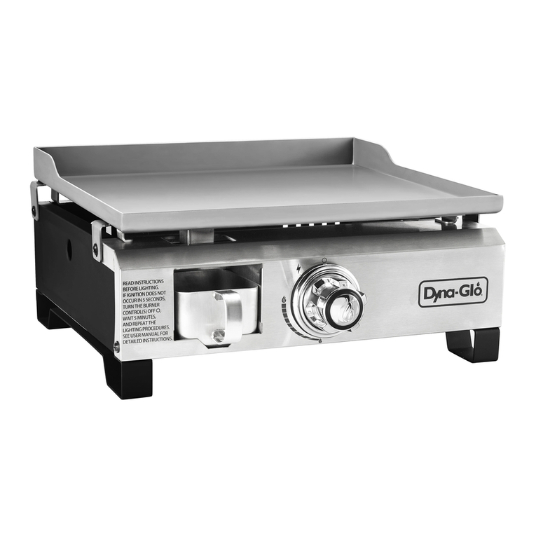
Important: Confirm that you have received all the parts included with your griddle model.
All Gas Countertop Griddle models
Materials included:
•1 griddle
•1 pressure regulator for natural gas installation
•1 conversion kit for propane gas installation (includes pilot orifice, gas injector, and nameplate)
•1 instruction guide
5RO_GCG_GUIDE (11/21)
2.4. LEVEL
WARNING
The griddle must be installed on a heatproof countertop or stand.
Once the unit is in its final position, level the griddle by adjusting the leveling feet. Make sure the griddle
is level in the front-to-back and side-to-side axis. It is recommended to level the unit each time it is moved.
Proper leveling prevents accidents and ensures optimal cooking performance.
NOTE : Always handle the unit with someone else helping. Attempting to do so alone may result in injury.
WARNING
In the case of a mobile installation on a base or wheeled stand, the installation must meet the following
standard requirements, where applicable:
•In the United States, the Connectors for Moveable Gas Appliances, or ANSI Z21.69
and the Quick Disconnect Devices for Use With Gas Fuel Appliances or ANSI Z21.41.
•In Canada, the Connectors for Moveable Gas Appliances Standard, or CSA 6.16,
and the Quick Disconnect Devices for Use With Gas Fuel Appliances Standard, or CSA 6.9.
2.5. ATTACHEMENT
In the case of a mobile installation, do not use the connector or gas supply piping to restrict the movement
of the griddle. To fasten, insert the griddle into a battery of equipment or attach the equipment stand to the back wall
with a chain shorter than the gas supply pipe.
NOTE : Fastening material is not included.

6RO_GCG_GUIDE (11/21)
2.6. PROPANE GAS CONVERSION
WARNING
The unit is factory assembled with natural gas components. Each griddle comes with a propane gas conversion kit
that includes gas injectors and pilot orifice. Only an authorized technician can make changes to the unit.
This step must be done before the connection to the gas power supply.
1. To change the gas injector, first put the griddle top in the open position and secure in place with the centre support.
2. Remove the burners by unscrewing the screws from the support.
3. Pull the burner back to gain access to the gas injector located in the thermostat. Repeat for all burners. (Figure 1)
Figure 1

7RO_GCG_GUIDE (11/21)
4. Remove the natural gas injector from the thermostat using a hex key. Replace with the propane gas injector
and screw the injector into the thermostat. Repeat this step for each thermostat. (Figure 2)
5. Replace and secure the burner(s) in their original position and screw on the burner support(s).
NOTE : The injector hole diameter for natural gas is 0.082” (#45) and 0.052” (#55) for propane gas.
Figure 2

8RO_GCG_GUIDE (11/21)
6. To change the pilot orifice, unscrew the pilot holder(s) by removing the two (2) bottom screws. (Figure 3)
7. Unscrew the lower part of the pilot with a hex key.
8. Remove the natural gas pilot orifice and replace with the propane orifice.
Repeat this step for each pilot. (Figure 4)
9. Return the pilot support(s) to the original position.
NOTE : The number and type of pilots vary depending on the griddle model.
Refer to the service parts chart for complete details on each griddle model.
NOTE : Be sure to remove the pressure regulator as it is only required for a natural gas installation.
10. Stick the propane gas nameplate included with the conversion kit over the original natural gas nameplate.
The nameplate is located on the side of the unit.
Figure 3 Figure 4
PILOT
ORIFICE

9RO_GCG_GUIDE (11/21)
2.7. CONNECTION
To connect the unit to the gas power supply, use the 1/2” NPT gas connector located on the back of the griddle
(Figure 5).
Install the regulator outside the unit for a natural gas installation, between the gas circuit and the gas connector.
Adjust the pressure to 7” W.C.
WARNING
When connecting the gas power supply to the unit connector, use a second wrench for tightening. This will prevent
movement of the internal piping.
WARNING
After connection and before ignition, open the gas supply valve and check the joints for leaks with soapy water.
Never use a flame to check for a gas leak.
ORIFICE DE
VEILLEUSE
Figure 5
PRESSURE
REGULATOR
1/2’’ NPT GAS
CONNECTOR

10 RO_GCG_GUIDE (11/21)
2.8. GAS PRESSURE CHECK
WARNING
For any pressure test above ½ psi (3.45 kPa), isolate the unit from the gas power supply by closing the shutoff valve.
1. To measure the gas pressure, remove the thermostat knob(s) and the indicator ring(s), unscrew the bolts
on the front panel, and remove the top panel. (Figure 6)
2. Unscrew the cap on the gas manifold and screw on the pressure gauge. (Figure 7)
3. Make sure the burner(s) are operating at maximum capacity during the pressure test. Operate all other equipment
connected to the gas source system at full capacity, then read the pressure.
4. Turn off all other equipment and take a second pressure reading. Normal pressure should be:
•7” W.C. for natural gas
•11” W.C. for propane gas
5. If the pressure varies by more than 1” W.C. refer to your gas supplier.
Figure 6
Figure 7
RO-GCG_figure_18.pdf 1 2021-09-01 16:27
CAP

11RO_GCG_GUIDE (11/21)
3. OPERATION
WARNING
Never leave the thermostat knob(s) in the MAXIMUM position when the plate is not in use.
This could cause the plate to overheat, turn black, and could cause damage.
3.1. IGNITION
1. Turn the thermostat(s) to the "OFF" position and wait five (5) minutes.
2. Lift the griddle top and secure in place with the centre support.
3. Open the units main gas supply.
4. Light on the pilot(s) manually. (Figure 8)
5. Make sure the pilot(s) are correctly lit before closing the griddle.
6. Set the thermostat(s) to the desired position.
Figure 8

12 RO_GCG_GUIDE (11/21)
3.2. BURNER ADJUSTMENT
To avoid weak and unstable burner flames or carbon monoxide emissions, adjust the burner’s air damper
by turning the thermostat to the maximum position. Observe the burner flames immediately:
•If the flames are unstable or do not penetrate through the holes in the burner, gradually close the air damper
until stable and consistent flames are obtained.
•If the flames are strong and show yellow glows, gradually open the air damper until the glows disappear.
3.3. FIRST USE
Factory plate protection
1. Before using the unit, heat the plate at 300 °F for five (5) minutes to burn off the protective coating.
2. Turn off the unit and let it cool down.
3. Wash the plate with soapy detergent or a mild cleaner to completely remove the residue.
4. Rinse with hot water and repeat the operation a second time.
3.4. PROLONGED SHUTDOWN
1. Turn the thermostats to the "OFF" position.
2. Turn off the units gas power supply.
NOTE : Be sure to properly condition the griddle before prolonged shutdown to prevent rusting and degradation
of your cooking surface.

13RO_GCG_GUIDE (11/21)
4.MAINTENANCE
WARNING
Check for oil build-up on the inner and outer walls of the chimney. If you find oil build-up on the chimney walls,
have the chimney cleaned by a maintenance service company to avoid fire hazard.
4.1. CONDITION
It is essential to coat the plate with oil immediately after use and to keep it oiled at all times to prevent rust.
NOTE : This step does not apply to plates with a polished chrome finish.
After cleaning the griddle, follow these steps to ensure optimal long-term performance:
1. Heat the griddle to 300 °F.
2. Apply a few ounces of frying oil.
3. Spread the oil with a soft cloth over the entire surface.
4. Wipe off excess oil.

14 RO_GCG_GUIDE (11/21)
4.2. CLEANING
Keep the griddle as clean as possible to prevent stains from charring the hot surfaces.
Regular cleaning of the griddle will ensure better cooking performance and a longer life for your unit.
NOTE: Cooking plates with a polished chrome (PC) finish are more energy efficient but require rigorous maintenance.
Refer to the specific maintenance instructions below to maintain optimum performance.
Every day, thoroughly clean exposed surfaces with a mild soap or other commercial cleaner designed for this purpose.
Remove, empty, and clean the grease drawer regularly.
•Polished steel plate
◽During use, regularly clean the plate with a scraper.
◽Each day, turn off the griddle, let it cool (to 300°F), pour room temperature water on the griddle,
and clean with a scraper.
◽Once a week, clean the surface of the plate thoroughly using a Scotch Brite© type abrasive or a scrub brush
as needed. Brush in the plate grain direction while it is still warm. If detergent is used, be sure to rinse well
with clear water after cleaning.
◽After cleaning, condition the plate as specified in these instructions.
•Plate with polished chrome finish (PC)
◽During use, regularly clean the plate with a chrome plate scraper. Never use an abrasive or a brick scraper
on the chrome finish.
◽Every day, clean the plate with a damp cloth and polish with a dry, soft cloth.
◽Once a week, use a non-abrasive, silicate-free cleaner like Bon Ami© for charred or blackened areas.
Rinse off the cleaner thoroughly with clear water and then polish with a soft dry cloth.

15RO_GCG_GUIDE (11/21)

16 RO_GCG_GUIDE (11/21)
5. SERVICE PARTS
5.1. ROGCG18
See figure 9 for identification of service parts
# Code Description Qty
1 913900224 Thermostat Knob OFF/150-400 °F 1
2 935350025 Cast Iron Burner 20 000 BTU 1
3
202101190 Natural Gas Injector hex 1/2" #45 1
202101211 Propane Gas Injector hex 1/2" #55 1
4 913200022 Thermostat OFF/150-400 °F, 48" Capillary Tube 1
5 913900226 Thermostat Adjustment Flange 1
6 913900227 Thermostat Flange Screws (2) 1
7 935150060 Convertible Pilot Light Adjusting Valve 1
8 935900036 Flexible 1/4" x 18" SS Gas Tubbing 1
9 935150063 Pressure Regulator for Gas Griddle 1
10 935150062 Convertible Pilot Light 1
11
935900040 Pilot Orifice 0,010 1
935900041 Pilot Orifice 0,014 1
12 202101009 Grease Pan Drawer 5'' x 20'' x 3'' 1
Pilot orifice Pilot orifice
Natural 935900041
(0.014)
935900042
(0.022)
Propane 935900040
(0.010)
935900041
(0.014)

17RO_GCG_GUIDE (11/21)
Figure 9
10
11
87
5
4
6
3
9
2
1
12

18 RO_GCG_GUIDE (11/21)
5.2. RO-GCG-24
See figure 10 for identification of service parts
# Code Description Qty
1 913900224 Thermostat Knob OFF/150-400 °F 2
2 935350025 Cast Iron Burner 20 000 BTU 2
3
202101190 Natural Gas Injector hex 1/2" #45 2
202101211 Propane Gas Injector hex 1/2" #55 2
4 913200022 Thermostat OFF/150-400 °F, 48" Capillary Tube 2
5 913900226 Thermostat Adjustment Flange 2
6 913900227 Thermostat Flange Screws (2) 2
7 935150060 Convertible Pilot Light Adjusting Valve 1
8 935900036 Flexible 1/4" x 18" SS Gas Tubbing 1
9 935150063 Pressure Regulator for Gas Griddle 1
10 202101041 Convertible Pilot Light 4⁄" 1
11
935900041 Pilot Orifice 0,014 1
935900042 Pilot Orifice 0,022 1
12 202101009 Grease Pan Drawer 5'' x 20'' x 3'' 1
Pilot orifice Pilot orifice
Natural 935900041
(0.014)
935900042
(0.022)
Propane 935900040
(0.010)
935900041
(0.014)

19RO_GCG_GUIDE (11/21)
Figure 10
2
3
6
4
5
7
1
12
9
10
11
8

20 RO_GCG_GUIDE (11/21)
5.3. RO-GCG-36
See figure 11 for identification of service parts
# Code Description Qty
1 913900224 Thermostat Knob OFF/150-400 °F 2
2 935350025 Cast Iron Burner 20 000 BTU 3
3
202101190 Natural Gas Injector hex 1/2" #45 2
202101211 Propane Gas Injector hex 1/2" #55 2
4 913200022 Thermostat OFF/150-400 °F, 48" Capillary Tube 2
5 913900226 Thermostat Adjustment Flange 2
6 913900227 Thermostat Flange Screws (2) 2
7 935150060 Convertible Pilot Light Adjusting Valve 1
8 935900036 Flexible 1/4" x 18" SS Gas Tubbing 1
9 935150063 Pressure Regulator for Gas Griddle 1
10 935150062 Convertible Pilot Light 1
11 202101049 Convertible Pilot Light 6-1/8" 1
12 935900040 Pilot Orifice 0,010 1
13
935900041 Pilot Orifice 0,014 2
935900042 Pilot Orifice 0,022 1
14 202101009 Grease Pan Drawer 5'' x 20'' x 3'' 1
Pilot orifice Pilot orifice
Natural 935900041
(0.014)
935900042
(0.022)
Propane 935900040
(0.010)
935900041
(0.014)
This manual suits for next models
5
Table of contents