Rosko RO-PGCE-18-1 User manual

2RO-PGCE_GUIDE (01/22)
1. WARNINGS AND CAUTIONS
WARNING
Any installation, adjustment, modification, repair, or maintenance not in accordance with applicable standards
may cause property damage, injury, or death. To ensure a safe installation and proper operation
of your Rosko equipment, please read this entire guide and keep it for future reference.
•This unit is intended for commercial use only.
•Installation must meet the requirements of the codes below, where applicable.
◽State codes or local codes, or in the absence of local codes:
◽the National Electrical Code ANSI/NFPA 70;
◽State codes or local codes, or in the absence of local codes:
◽the Canadian Electrical Code CSA C22.1.
•The installation of this appliance must be done by a certified technician, where required by law.
•Do not store fuels or other flammable materials near the unit.
•In the event of a malfunction, disconnect the unit power supply and contact a service technician.
WARNING
Keep a copy of these instructions in a visible location1.
1
This guide is updated as new information or new products become available.
Visit our website rosko-julien.ca for the most recent version of these documents.

3RO-PGCE_GUIDE (01/22)
TABLE OF CONTENT
1. WARNINGS ET CAUTIONS . . . . . . . . . . . . . . . . . . . . . . . . . . . . . . . . . . . . . . . . . . . . . . . . . . . . . . . . . . . . . . . . . . . . . . . . . . . . . . . . . . . . . . . . . . . . . . . . 2
2. PLANNING AND INSTALLATION . . . . . . . . . . . . . . . . . . . . . . . . . . . . . . . . . . . . . . . . . . . . . . . . . . . . . . . . . . . . . . . . . . . . . . . . . . . . . . . . . . . . . . . . . . . 4
2.1. CLEARANCE .......................................................................................................... 4
2.2. RECEPTION AND INSPECTION ....................................................................................... 4
2.3. LEVEL ................................................................................................................. 5
2.4. ATTACHEMENT ....................................................................................................... 5
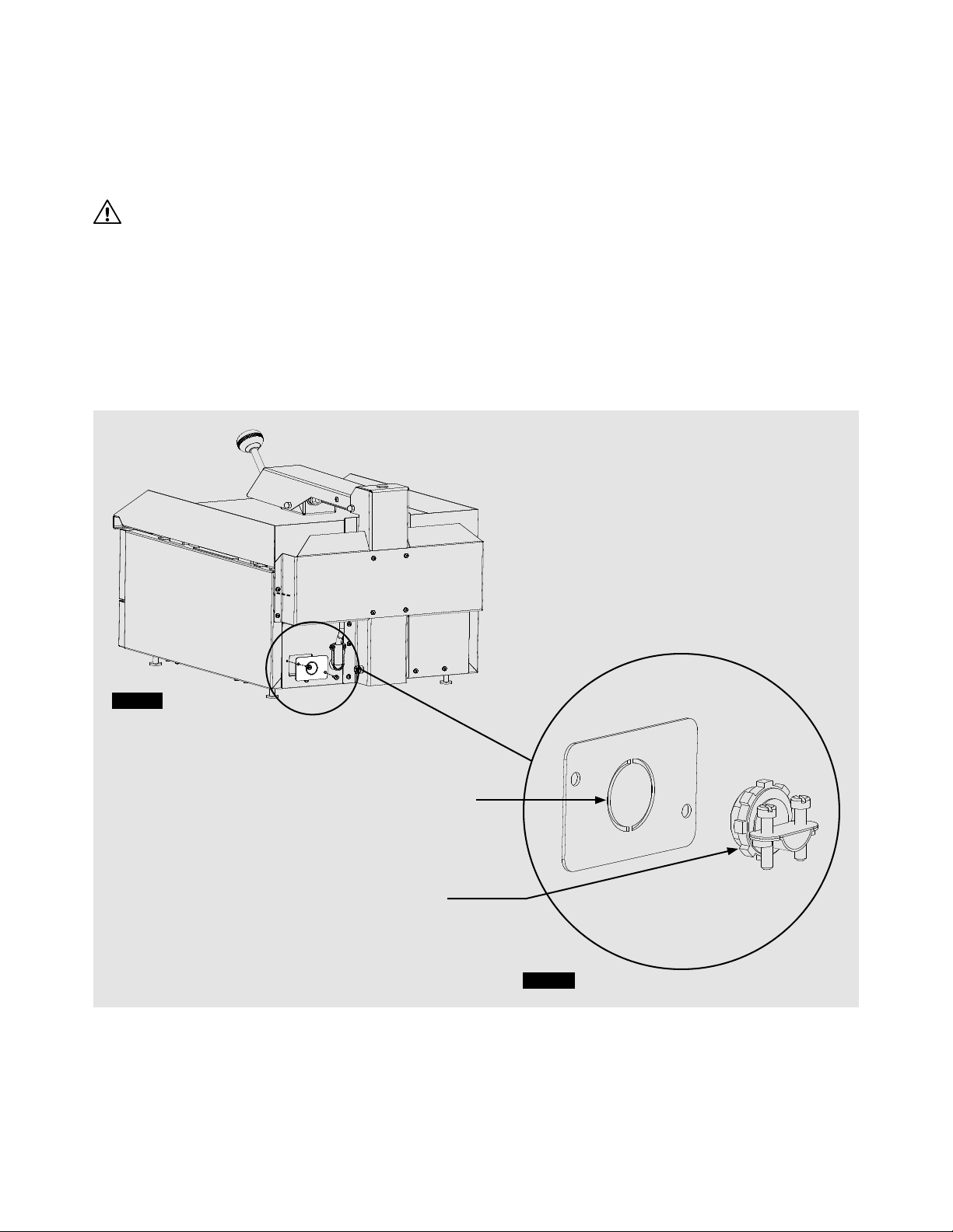
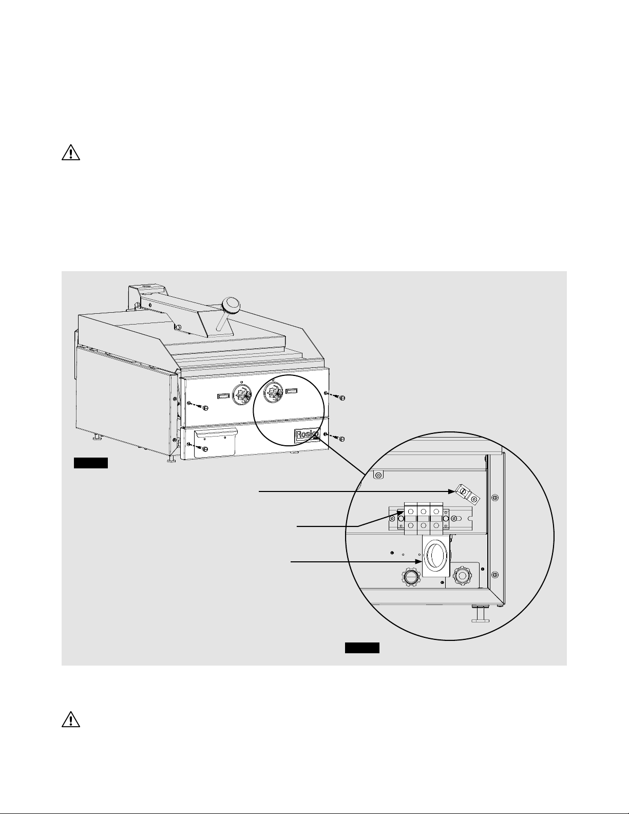
2.5. CONNECTION ........................................................................................................ 6
3. OPERATION . . . . . . . . . . . . . . . . . . . . . . . . . . . . . . . . . . . . . . . . . . . . . . . . . . . . . . . . . . . . . . . . . . . . . . . . . . . . . . . . . . . . . . . . . . . . . . . . . . . . . . . . . . . . . . . 8
3.1. FIRST USE ............................................................................................................ 8
3.2. IGNITION ............................................................................................................. 8
3.3. PROLONGED SHUTDOWN ........................................................................................... 9
4. MAINTENANCE . . . . . . . . . . . . . . . . . . . . . . . . . . . . . . . . . . . . . . . . . . . . . . . . . . . . . . . . . . . . . . . . . . . . . . . . . . . . . . . . . . . . . . . . . . . . . . . . . . . . . . . . . . . 9
4.1. CONDITION ........................................................................................................... 9
4.2. CLEANING .............................................................................................................9
5. ELECTRICAL DIAGRAM . . . . . . . . . . . . . . . . . . . . . . . . . . . . . . . . . . . . . . . . . . . . . . . . . . . . . . . . . . . . . . . . . . . . . . . . . . . . . . . . . . . . . . . . . . . . . . . . . . 11
5.1. RO-PGCE-18 ........................................................................................................ 11
6. SERVICE PARTS . . . . . . . . . . . . . . . . . . . . . . . . . . . . . . . . . . . . . . . . . . . . . . . . . . . . . . . . . . . . . . . . . . . . . . . . . . . . . . . . . . . . . . . . . . . . . . . . . . . . . . . . . 12
6.1. RO-PGCE-18 ........................................................................................................ 12
7. SPECIFICATIONS . . . . . . . . . . . . . . . . . . . . . . . . . . . . . . . . . . . . . . . . . . . . . . . . . . . . . . . . . . . . . . . . . . . . . . . . . . . . . . . . . . . . . . . . . . . . . . . . . . . . . . . . . 15
CONTACT US . . . . . . . . . . . . . . . . . . . . . . . . . . . . . . . . . . . . . . . . . . . . . . . . . . . . . . . . . . . . . . . . . . . . . . . . . . . . . . . . . . . . . . . . . . . . . . . . . . . . . . . . . . . . . . . . 16

4RO-PGCE_GUIDE (01/22)
2.PLANNING AND INSTALLATION
Congratulations on the purchase of your new
Rosko electric countertop panini grill!
To maximize the use and durability of your unit, we recommend that you follow the instructions in this guide.
Installation, operation, and maintenance procedures must be followed for warranty protection to apply.
2.1. CLEARANCE
It is essential to observe the following minimum clearance when planning the installation of the unit
and during the installation:
•Construction with combustible materials:
◽1’’ (27 mm) at the back and on each side of the panini grill
•Construction with non-combustible materials:
◽0’’ (0 mm) at the back and on each side of the panini grill
•Provide adequate space for the unit operation and maintenance.
2.2. RECEPTION AND INSPECTION
This unit has been inspected and verified before shipment. Upon receipt, check immediately for damage
with the delivery person present. If necessary, make your claim immediately.
The warranty is limited to the replacement of defective parts under normal use. No claims will be accepted
for breakage resulting from improper installation, improper operation, or unauthorized service before installation.
Before installation, make sure the specifications of the electric countertop panini grill match the type
of electric supply. Refer to the nameplate on the side of the unit.
Important: Confirm that you have received all the parts included with your panini grill model.
All Electric Countertop Panini Grill Models
Materials included:
•1 panini grill
•1 instruction guide

5RO-PGCE_GUIDE (01/22)
2.3. LEVEL
WARNING
The panini grill must be supported by a heatproof counter or stand.
Once the unit is in its final position, level the panini grill by adjusting the leveling feet. Make sure the panini grill
is level in the front-to-back and side-to-side axis. It is recommended to level the unit each time it is moved.
Proper leveling prevents accidents and ensures optimal cooking performance.
NOTE: Always handle the unit with someone else helping. Attempting to do so alone may result in injury.
2.4. ATTACHEMENT
WARNING
The unit must be installed with restraints to counteract possible stress on the electrical circuit.
Do not use the connector or power supply wire to restrict the unit movement. Fastening can be done by inserting
the panini grill into a battery of equipment or by attaching the grill to the back wall with a ring and a chain
shorter than the power cord.
NOTE: Fastening material is not included.
For installation on a moving surface with wheels, install the mounting device on the base used.
The restriction must also counteract the stress on the connector and on the electrical supply wire.
WARNING
Always turn the panini grill power off before removing the fastener.

6RO-PGCE_GUIDE (01/22)
2.5. CONNECTION
The wire entry for the connection is a ⁄” knockout located at the back of the panini grill.
Use a ⁄” commercial electrical connector (not included) to insert the electrical supply wire into the unit.
The connection must be done by a certified technician or electrician.
WARNING
Installation must meet the requirements of the codes below, where applicable:
•State codes or local codes, or in the absence of local codes:
The National Electrical Code ANSI/NFPA 70;
•State codes or local codes, or in the absence of local codes:
Canadian Electrical Code CSA C22.1.
1. Manually remove the 3/4” knockout located behind the panini grill.
2. Remove the plate containing the knockout at the back of the unit by unscrewing the two (2) fixing screws. (Figure 1)
3. Install and secure the commercial electrical connector (not included) in the hole provided on the plate. (Figure 2)
Figure 1
Figure 2
KNOCKOUT HOLE ⁄’’
COMMERCIAL
CONNECTOR ⁄’’

7RO-PGCE_GUIDE (01/22)
4. To reach the terminal block, remove the grease drawer, unscrew the four (4) bolts in front of the unit
and remove the two (2) front panels. (Figure 3)
5. Insert and secure the correct length of unsheathed wire in the connector to direct it to the terminal block
located on the front of the unit.
6. Make sure the end of the wire fits into the wire grommets before it reaches the terminal block. (Figure 4)
WARNING
Use a metal wire that can withstand a temperature of 300 °F (150 °C). The wire size must also support
the operational current (A) listed on the device spec sheet..
7. Replace the plate by screwing in the two (2) fixing screws and ensuring that the electrical connector
is firmly in place.
8. Make the electrical connections and grounding according to the electrical diagram. (Figure 4)
NOTE: See figure 6 for details on electrical connections.
9. Replace the grease drawer and the two (2) front panels in their original position by tightening the four (4) bolts.
WARNING
Be sure not to pinch the internal wiring of the unit when replacing the front panels.
Figure 3
Figure 4
TERMINAL BLOCK
GROUND
WIRE GROMMET

8RO-PGCE_GUIDE (01/22)
3. OPERATION
WARNING
Never leave the thermostat knob(s) in the MAXIMUM position when the plate is not in use.
This could cause the plate to overheat, turn black, and could cause damage.
3.1. FIRST USE
Factory plate protection
1. Before using the unit, heat the plates to 300 °F for five (5) minutes to burn off the protective coating.
2. Turn off the unit nd let it cool down.
3. Wash the two (2) plates with soapy water, a mild detergent or cleaner to completely remove the residue.
4. Rinse with hot water and repeat the operation a second time.
3.2. IGNITION
1. Turn the control knobs to the “OFF” position.
2. Make sure that the cooking plates are well oiled.
3. Adjust the thermostat to the desired position. The left red indicator light will turn on to indicate that
the bottom plate element is heating.
4. Adjust the infinity control to the desired position. The right red indicator light will turn on to indicate that
the top plate element is heating. (Figure 5)
NOTE : Bottom plate cooking is controlled by a thermostat and top plate cooking is controlled by a HI/LO control.
NOTE: We recommend preheating the plate. To do this, adjust the controls to the desired temperature
about 20 minutes before you start cooking.
Figure 5
BOTTOM PLATE
INDICATOR LIGHT
THERMOSTAT
TOP PLATE
INDICATOR LIGHT
INFINITY CONTROL

9RO-PGCE_GUIDE (01/22)
3.3. PROLONGED SHUTDOWN
1. Turn the control knob to the “OFF” position.
2. Turn the thermostat knob to the “OFF” position.
3. Turn off the main electric supply.
NOTE: Be sure to condition the two (2) plates before prolonged shutdown to prevent rusting and degradation
of your cooking surface.
4.MAINTENANCE
4.1. CONDITION
It is essential to coat the plates with oil immediately after use and to keep it oiled at all times to prevent rust.
After cleaning the plates, follow these steps:
1. Set the thermostat to 300 °F.
2. Activate the infinity control to medium.
3. Apply a few ounces of frying oil on the two (2) plates.
4. Spread the oil with a soft cloth over the entire surface.
5. Wipe off excess oil
4.2. CLEANING
Keep the panini grill as clean as possible to prevent stains from charring the hot surfaces. Regular cleaning
of the panini grill will ensure better cooking performance and a longer life for your unit.
Every day, thoroughly clean exposed surfaces with a mild soap or other commercial cleaner designed for this purpose.
Remove, empty, and clean the grease drawer regularly.
•Polished steel cooking plate
◽During use, regularly clean the plate with a scraper.
◽Each day, turn off the panini grill, let it cool (to 300 °F), pour room temperature water on the bottom plate
and clean with a scraper.
◽Once a week, clean the plate surfaces thoroughly using a Scotch Brite™ type abrasive or a scrub brush
as needed. Brush in the plate grain direction while it is still warm. If detergent is used, be sure to rinse well
with clear water after cleaning.
◽After cleaning, condition the two (2) plates as specified in section 4.1.

10 RO-PGCE_GUIDE (01/22)

11RO-PGCE_GUIDE (01/22)
Figure 6
5. ELECTRICAL DIAGRAM
5.1. RO-PGCE-18
RO-PGCE-18 | GRILLE-PANINI DE COMPTOIR ÉLECTRIQUE | ELECTRIC COUNTERTOP PANINI GRILL

12 RO-PGCE_GUIDE (01/22)
6. SERVICE PARTS
6.1. RO-PGCE-18
See figure 7for identification of service parts
# Code Description Qty
1 202101007 Grease Pan Drawer for Gas Griddle 1
2 913900239 Knob Ring for Control OFF/HI-LO 1
3 913200047 Infinite Switch 15 A - 240 V 1
4 913900238 Knob Ring for Control OFF/100-450 °F 1
5 913900220 Control Knob for Commutable Ring 2
6 910300014 Red Square Indicator Light 250 V 2
7 913200028 Thermostat OFF/100-450 °F 1
8
911200099 Element 4000 W for 240 V Electric 18'' Equipment 1
913200041 Element 4000 W for 208 V Electric 18'' Equipment 1
9
911200101 Top Element 2000 W for 240 V Electric Panini Grill 1
911200120 Top Element 2000 W for 208 V Electric Panini Grill 1

13RO-PGCE_GUIDE (01/22)
Figure 7
A
DÉTAIL A
ÉCHELLE 1 : 4
2
3
8
7
1
5
4
6
9

14 RO-PGCE_GUIDE (01/22)

15RO-PGCE_GUIDE (01/22)
7. SPECIFICATIONS
This guide is dedicated to the Rosko electric countertop panini grills listed below.
Models Total output Number of
elements
Number of
controls Voltage Amperage
1 phase
Amperage
3 phases
(B) (W) (R)
RO-PGCE-18-1
6 000 W 2 1
208 V 28,80 A 9,60 A 28,80 A 19,70 A
RO-PGCE-18-2 240 V 25,00 A 8,30 A 25,00 A 16,60 A
Models Width Depth Total height Cooking surface Weight Packaging dimension
(W x D x H)
RO-PGCE-18-1
18'' - 457 mm 26" - 660 mm 17" - 432 mm 17 ⁄ x 19''
444 x 483 mm 170 lb - 77 kg 20 x 30 x 28"
508 x 762 x 711 mm
RO-PGCE-18-2
2''2''
51mm51mm
17''17''
432mm432mm
This manual suits for next models
1
Table of contents
Popular Grill manuals by other brands

Nova
Nova 110201 manual

MyOUTDOORKITCHEN
MyOUTDOORKITCHEN CGU301i-F2G-1 User manual and installation instructions

Weber
Weber Genesis II S-335 owner's manual

Gastroback
Gastroback Design Grill-Barbecue Advanced operating instructions

Uniflame
Uniflame GBC1762WSP-U owner's manual

Napoleon
Napoleon ROGUE XT625-1 Quick assembly guide