Ross PIVOTCam-SE User manual

PIVOTCam-SE
User Manual

Thank You For Choosing Ross
You've made a great choice. We expect you will be very happy with your
purchase of Ross Technology.
Our mission is to:
1. Provide a Superior Customer Experience
• offer the best product quality and support
2. Make Cool Practical Technology
• develop great products that customers love
Ross has become well known for the Ross Video Code of Ethics. It
guides our interactions and empowers our employees. I hope you enjoy
reading it below.
If anything at all with your Ross experience does not live up to your
expectations be sure to reach out to us at solutions@rossvideo.com.
David Ross
CEO, Ross Video
dross@rossvideo.com
Ross Video Code of Ethics
Any company is the sum total of the people that make things happen. At
Ross, our employees are a special group. Our employees truly care about
doing a great job and delivering a high quality customer experience
every day. This code of ethics hangs on the wall of all Ross Video
locations to guide our behavior:
1. We will always act in our customers' best interest.
2. We will do our best to understand our customers' requirements.
3. We will not ship crap.
4. We will be great to work with.
5. We will do something extra for our customers, as an apology, when
something big goes wrong and it's our fault.
6. We will keep our promises.
7. We will treat the competition with respect.
8. We will cooperate with and help other friendly companies.
ii • Thank You For Choosing Ross — PIVOTCam-SE User Manual

9. We will go above and beyond in times of crisis. If there's no one to
authorize the required action in times of company or customer crisis
- do what you know in your heart is right. (You may rent helicopters
if necessary.)
PIVOTCam-SE User Manual — Thank You For Choosing Ross • iii

Document Information
• Ross Part Number: 5000DR-304-01
• Release Date: January, 2020.
Copyright
©2020 Ross Video Limited, Ross®and any related marks are trademarks
or registered trademarks of Ross Video Limited. All other trademarks
are the property of their respective companies. PATENTS ISSUED
and PENDING. All rights reserved. No part of this publication may be
reproduced, stored in a retrieval system, or transmitted in any form or by
any means, mechanical, photocopying, recording or otherwise, without
the prior written permission of Ross Video. While every precaution has
been taken in the preparation of this document, Ross Video assumes no
responsibility for errors or omissions. Neither is any liability assumed for
damages resulting from the use of the information contained herein.
Adobe® and Flash® are either registered trademarks or trademarks of
Adobe Systems Incorporated in the United States and/or other countries.
VideoLAN, VLC, VLC media player and x264 are trademarks of the
videoLAN registered non-profit organization.
Important Regulatory and Safety Notices to
Service Personnel
Before using this product and any associated equipment, refer to the “
Important Safety Instructions ” listed in the front of this manual to
avoid personnel injury and to prevent product damage.
Product may require specific equipment, and/or installation procedures
to be carried out to satisfy certain regulatory compliance requirements.
Notices have been included in this publication to call attention to these
specific requirements.
Symbol Meanings
Protective Earth: This symbol identifies a Protective Earth (PE)
terminal, which is provided for connection of the supply system's
protective earth (green or green/yellow) conductor.
Important: This symbol on the equipment refers you to important
operating and maintenance (servicing) instructions within the Product
Manual Documentation. Failure to heed this information may present a
major risk of damage or injury to persons or equipment.
iv • Document Information — PIVOTCam-SE User Manual

Warning: The symbol with the word “ Warning ” within the equipment
manual indicates a potentially hazardous situation which, if not
avoided, could result in death or serious injury.
CAUTION: The symbol with the word “ Caution ” within the
equipment manual indicates a potentially hazardous situation which,
if not avoided, may result in minor or moderate injury. It may also be
used to alert against unsafe practices.
Warning Hazardous Voltages: This symbol is intended to alert the
user to the presence of uninsulated “ dangerous voltage ” within the
product enclosure that may be of sufficient magnitude to constitute a
risk of shock to persons.
ESD Susceptibility: This symbol is used to alert the user that an
electrical or electronic device or assembly is susceptible to damage
from an ESD event.
Important Safety Instructions
1. Read Instructions All the safety and operating instructions should
be read before the product is operated.
2. Retain Instructions The safety and operating instructions should be
retained for future reference
3. Heed Warnings All warnings on the product and the operating
instructions should be adhered to.
4. Follow Instructions All operating and use instructions should be
followed.
5. The camera power input range is 100-240VAC (50-60Hz). Ensure
the power supply input is within this range before powering on.
6. The camera power voltage is 12VDC with a rated current of 2A. We
suggest you use it with the original power supply adapter supplied
by the factory.
7. Please keep the power cable, video cable, and control cable in a safe
place. Protect all cables, especially the connectors.
8. Operational environment: 0°C-50°C, humidity less than 90%.
9. To avoid any danger, do not put anything inside the camera, and
keep it away from corrosive liquids.
10. Avoid stress, vibration, and damp during transportation, storage, and
installation.
11. Do not detach the camera housing and cover. For any service, please
contact the authorized dealer.
12. RF cable and control cable should be individually shielded, and
cannot be substituted with other cables.
PIVOTCam-SE User Manual — Document Information • v
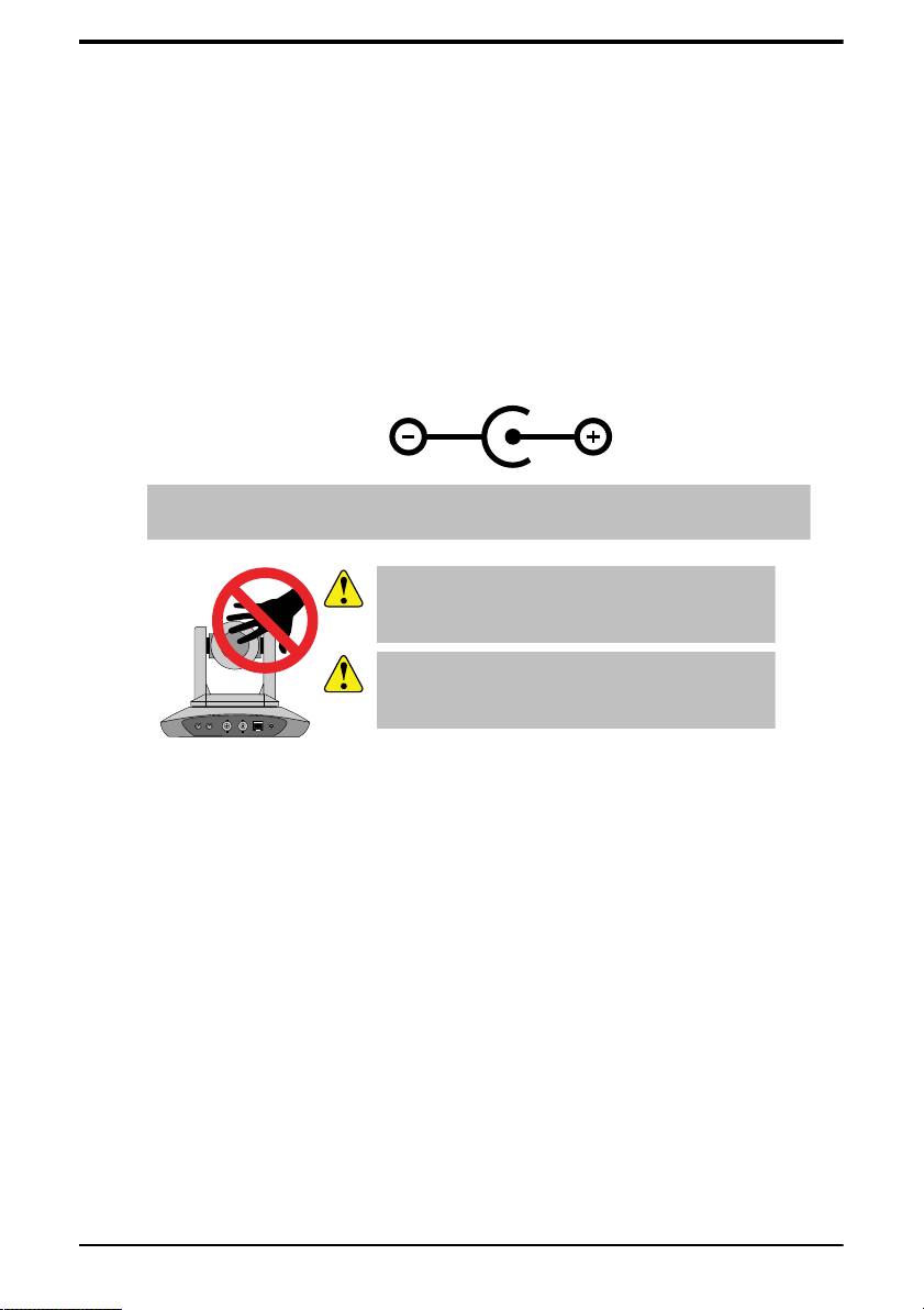
13. Do not direct the camera lens towards a strong light source, such as
the sun or an intense light.
14. Use a dry soft cloth to clean the camera housing. A neutral cleaning
agent can be applied when needed. To avoid damage to the camera
lens, never use strong or abrasive cleaning agents on the camera
housing.
15. Do not move the camera by holding the camera head. To avoid
mechanical trouble, do not rotate the camera head by hand.
16. Put the camera on a fixed, smooth desk or platform. The camera
should not be leaning on anything when installed.
17. Power Supply Polarity:
Note: The video quality may be affected by specific frequencies in
electromagnetic field.
IN---RS232---OUT HD-SDI GENLOCK LAN DC12V
CAUTION: Do NOT pick up the camera by the
lens barrel. Doing so may damage the rotary
mechanism and internal cables.
CAUTION: Do NOT move or rotate the lens
barrel by hand. Doing so may damage the rotary
mechanism as well as the rotation limiters.
Warranty and Repair Policy
Ross Video Limited (Ross) warrants its cameras and related options, to
be free from defects under normal use and service for a period of ONE
YEAR from the date of shipment.
Warranty repairs will be conducted at Ross, with all shipping FOB Ross
dock. If repairs are conducted at the customer site, reasonable out-of-
pocket charges will apply. At the discretion of Ross, and on a temporary
loan basis, plug in circuit boards or other replacement parts may be
supplied free of charge while defective items undergo repair. Return
packing, shipping, and special handling costs are the responsibility of the
customer.
This warranty is void if products are subjected to misuse, neglect,
accident, improper installation or application, or unauthorized
modification.
vi • Document Information — PIVOTCam-SE User Manual

In no event shall Ross Video Limited be liable for direct, indirect,
special, incidental, or consequential damages (including loss of profit).
Implied warranties, including that of merchantability and fitness for a
particular purpose, are expressly limited to the duration of this warranty.
This warranty is TRANSFERABLE to subsequent owners, subject to
Ross Video's notification of change of ownership.
Environmental Information
The equipment that you purchased required the extraction and use
of natural resources for its production. It may contain hazardous
substances that could impact health and the environment.
To avoid the potential release of those substances into the environment
and to diminish the need for the extraction of natural resources, Ross
Video encourages you to use the appropriate take-back systems. These
systems will reuse or recycle most of the materials from your end-of-life
equipment in an environmentally friendly and health conscious manner.
The crossed-out wheeled bin symbol invites you to use these systems.
If you need more information on the collection, reuse, and recycling
systems, please contact your local or regional waste administration.
You can also contact Ross Video for more information on the
environmental performances of our products.
Company Address
Ross Video Limited — 8 John Street Iroquois, Ontario, Canada, K0E
1K0
Ross Video Incorporated — P.O. Box 880, Ogdensburg, New York,
USA, 13669-0880
General Business Office: (+1)613-652-4886
Fax: (+1)613-652-4425
Toll Free Technical Support (North
America):
1-844-652-0645
PIVOTCam-SE User Manual — Document Information • vii

Toll Free Technical Support
(International):
+800 1005 0100
Technical Support: (+1)613-652-4886
After Hours Emergency: (+1)613-349-0006
E-Mail (Support): techsupport@rossvideo.com
E-Mail (General): solutions@rossvideo.com
Website www.rossvideo.com
Technical Support
At Ross Video, we take pride in the quality of our products, but if a
problem does occur, help is as close as the nearest telephone.
Our 24-Hour Hot Line service ensures you have access to technical
expertise around the clock. After-sales service and technical support
are provided directly by Ross Video personnel. During business hours
(eastern standard time), technical support personnel are available by
telephone. Outside of normal business hours and on weekends, a direct
emergency technical support phone line is available. If the technical
support personnel who is on call does not answer this line immediately,
a voice message can be left and the call will be returned shortly. Our
Technical support staff are available to react to any problem and to do
whatever is necessary to ensure customer satisfaction.
Supporting Documentation
Ross Video provides a wide variety of helpful documentation for the
setup and support of your equipment. Most of this documentation can be
found on the Ross Video website (www.rossvideo.com), or on the Ross
Video Community site (discussions.rossvideo.com/)
viii • Document Information — PIVOTCam-SE User Manual

Contents
Box Contents..............................................................................11
Camera Overview.......................................................................12
Cabling........................................................................................ 13
Supported Reference Formats.................................................................................. 13
Cabling for Control via Ethernet Port........................................................................ 14
Cabling for Control via Serial Port............................................................................ 15
DIP Switches..............................................................................................................16
PTZ Camera Control Plugin......................................................18
Remote Control.......................................................................... 19
On-screen Menu System...........................................................21
System....................................................................................................................... 21
Exposure.................................................................................................................... 21
Image......................................................................................................................... 22
Quality........................................................................................................................ 23
PTZ.............................................................................................................................23
Format........................................................................................................................ 24
IP................................................................................................................................ 24
Reset.......................................................................................................................... 24
INFO...........................................................................................................................25
Web Interface..............................................................................26
To Log Into the Web Interface...................................................................................26
Preview.......................................................................................................................27
PTZ Control................................................................................................ 27
Preset Control.............................................................................................28
Settings...................................................................................................................... 28
Video Encoding.......................................................................................... 28
Image Parameters......................................................................................30
RTMP Settings........................................................................................... 35
RTP Multicast Settings...............................................................................35
Ethernet...................................................................................................... 35
CAM Firmware Upgrade............................................................................ 36
Reset to Default......................................................................................... 37
Account....................................................................................................... 38
PIVOTCam-SE User Manual — Contents • ix

Troubleshooting......................................................................... 40
Specifications............................................................................. 41
Ports............................................................................................ 43
RS232 (VISCA IN/OUT)............................................................................................ 43
x • Contents — PIVOTCam-SE User Manual
Table of contents
Other Ross Security Camera manuals


