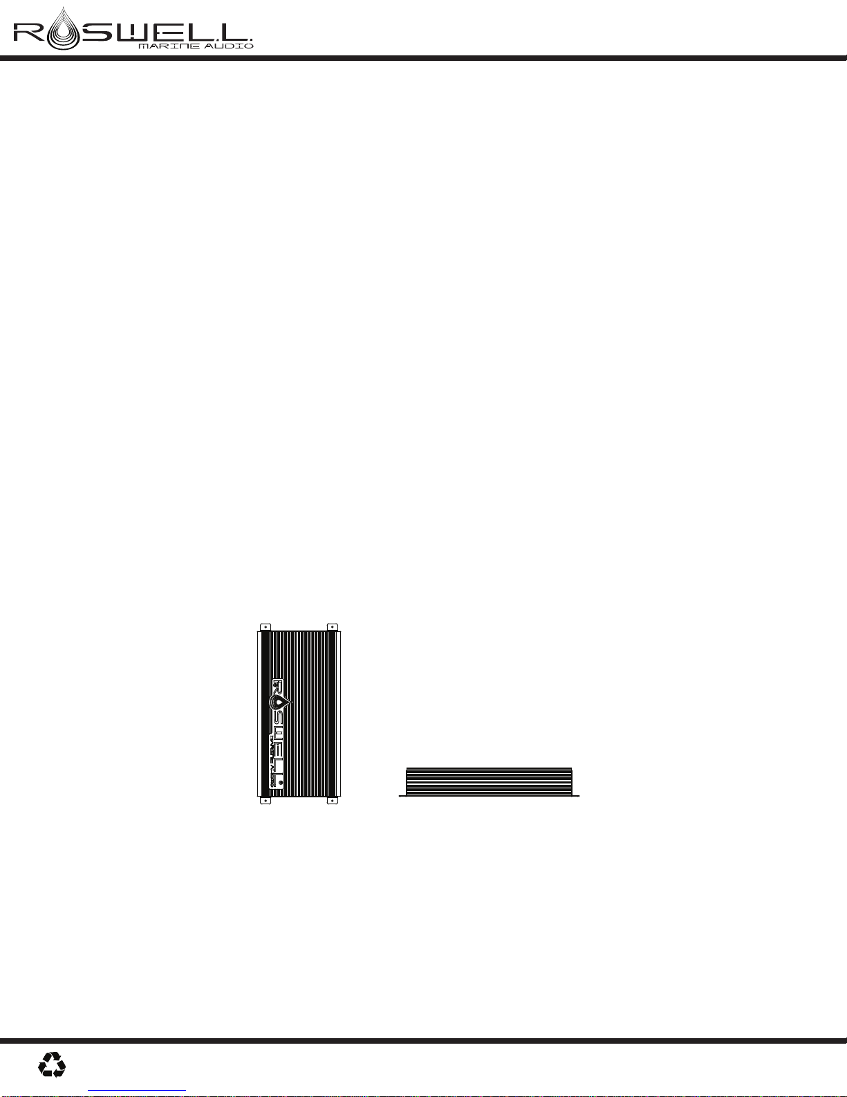
RMA 500.1 & RMA 500.4 Amplifier Owner’s Manual
Rev. 09-Mar-10 Pg. 7/8
ROSWELL MARINE AUDIO WARRANTY AND SERVICE GUIDELINES
Roswell WakeAir warrants all new RMA Series amplifiers against defects in material and workmanship
for a period of ONE (1) YEAR from the original date of purchase. This warranty is not transferable and
applies only to the original retail purchaser from an authorized Roswell Marine Audio retailer. Upon
inspection by Roswell Wake Air, should service be necessary under this warranty for any reason due to
manufacturer defects, Roswell Wake Air will, at our own discretion, repair or replace the defective
product with new or similar conditioned product at no charge.
THIS WARRANTY DOES NOT COVER INSTALLATION OR DAMAGE RESULTING FROM ACCIDENT,
MISUSE, ABUSE, IMPROPER WIRING, OPERATION OUTSIDE OF THE MANUFACTURERS REC-
OMMENDATIONS OR SPECIFICATIONS, OR AGAINST INSTRUCTIONS IN OWNERS MANUAL. IN
ADDITION, ANY PRODUCT THAT HAS BEEN OPENED, TAMPERED WITH OR MODIFIED, OR IF
ANY SERIAL NUMBERS HAVE BEEN REMOVED, WILL NOT BE COVERED BYANY PART OF THE
MANUFACTURES WARRANTY.
All warranty claims must first be made in direct contact with Roswell Wake Air’s warranty department.
When first contact is made the warranty representative will issue an RA # to open a claim. All warranty
returns should be sent to Roswell Wake Air freight prepaid and must be accompanied by proof of
purchase (a copy of original sales receipt). Direct returns from consumers or non-authorized retailers
will be refused unless specifically authorized by Roswell Wake Air with a valid return authorization
number (RA#).
All warranty returns should be packed in the original packaging and must be accompanied by a copy of
the original sales receipt. Product damage during shipping will not be covered under this warranty. The
customer or retailer may choose to have this damage repaired at the normal “Out of Warranty” repair
cost.
In no event will Roswell Wake Air be liable for incidental, consequential, or other damages resulting
from the use of this product. This includes but is not limited to, damage of hearing, property of person,
damage based upon inconvenience or on loss of use of the product, and to the extent permitted by law,
damages for personal injury.
This warranty applies to products being sold and used in the United States of America and Canada. In
all other countries please contact your authorized Roswell Wake Air representative.
For warranty and non-warranty repairs, please contact Roswell Wake Air:
Phone: 1.780.962.0868
Email: warranty@roswellwakeair.com
www.roswellwakeair.com